Page 1034 of 2389
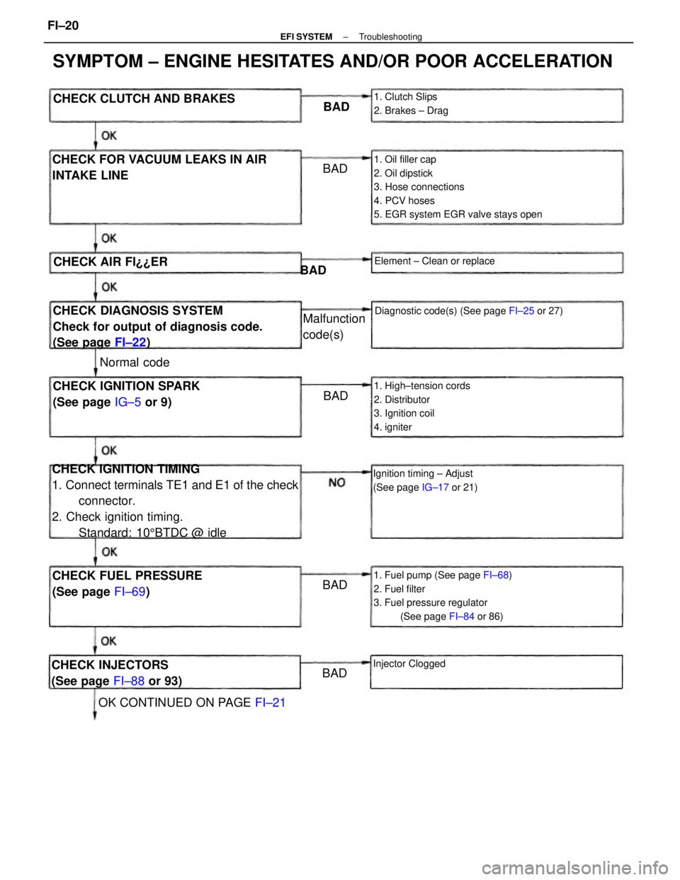
CHECK IGNITION TIMING
1. Connect terminals TE1 and E1 of the check
connector.
2. Check ignition timing.
Standard: 105BTDC @ idle
1. Oil filler cap
2. Oil dipstick
3. Hose connections
4. PCV hoses
5. EGR system EGR valve stays open
SYMPTOM ± ENGINE HESITATES AND/OR POOR ACCELERATION
1. Fuel pump (See page FI±68)
2. Fuel filter
3. Fuel pressure regulator
(See page FI±84 or 86)
CHECK DIAGNOSIS SYSTEM
Check for output of diagnosis code.
(See page FI±22) CHECK FOR VACUUM LEAKS IN AIR
INTAKE LINE
1. High±tension cords
2. Distributor
3. Ignition coil
4. igniterCHECK IGNITION SPARK
(See page IG±5 or 9)
CHECK FUEL PRESSURE
(See page FI±69)
Diagnostic code(s) (See page FI±25 or 27)
Ignition timing ± Adjust
(See page IG±17 or 21)
CHECK INJECTORS
(See page FI±88 or 93)
OK CONTINUED ON PAGE FI±21 CHECK CLUTCH AND BRAKES
1. Clutch Slips
2. Brakes ± Drag
Element ± Clean or replace
Malfunction
code(s)
Injector Clogged
CHECK AIR FI¿¿ER
Normal codeBAD
BADBAD
BADBAD BAD
± EFI SYSTEMTroubleshootingFI±20
Page 1074 of 2389
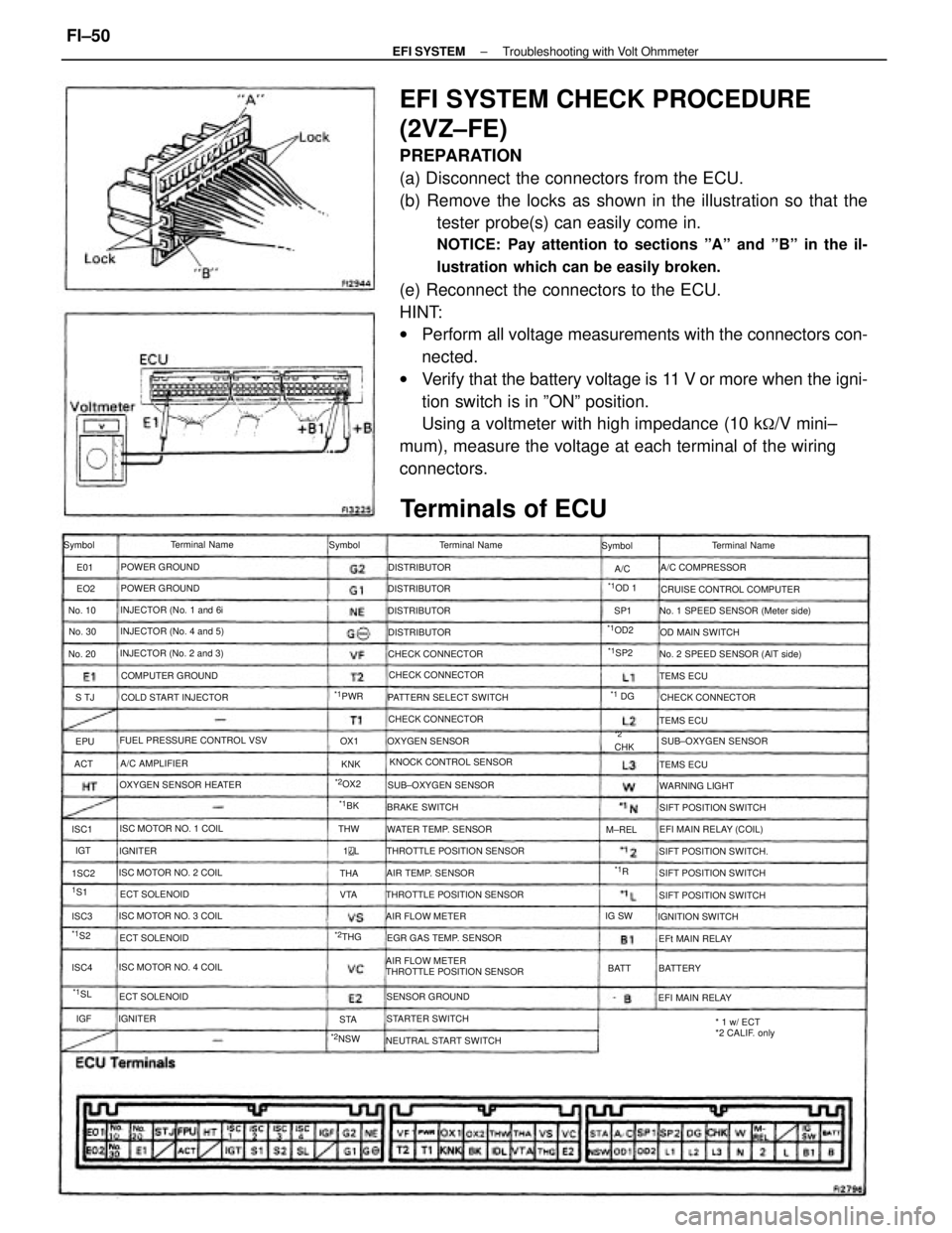
EFI SYSTEM CHECK PROCEDURE
(2VZ±FE)
PREPARATION
(a) Disconnect the connectors from the ECU.
(b) Remove the locks as shown in the illustration so that the
tester probe(s) can easily come in.
NOTICE: Pay attention to sections ºAº and ºBº in the il-
lustration which can be easily broken.
(e) Reconnect the connectors to the ECU.
HINT:
wPerform all voltage measurements with the connectors con-
nected.
wVerify that the battery voltage is 11 V or more when the igni-
tion switch is in ºONº position.
Using a voltmeter with high impedance (10 k
�/V mini±
mum), measure the voltage at each terminal of the wiring
connectors.
AIR FLOW METER
THROTTLE POSITION SENSOR
Terminals of ECU
No. 1 SPEED SENSOR (Meter side)
No. 2 SPEED SENSOR (AlT side)
THROTTLE POSITION SENSOR FUEL PRESSURE CONTROL VSV
THROTTLE POSITION SENSORCRUISE CONTROL COMPUTER
* 1 w/ ECT
*2 CALIF. only KNOCK CONTROL SENSOR PATTERN SELECT SWITCH
OXYGEN SENSOR HEATER
NEUTRAL START SWITCHEGR GAS TEMP. SENSOR INJECTOR (No. 2 and 3)INJECTOR (No. 4 and 5)
SIFT POSITION SWITCH.
ISC MOTOR NO. 3 COILINJECTOR (No. 1 and 6i
ISC MOTOR NO. 1 COIL
ISC MOTOR NO. 4 COILSIFT POSITION SWITCH ISC MOTOR NO. 2 COILWATER TEMP. SENSORSUB±OXYGEN SENSOR
SIFT POSITION SWITCH COLD START INJECTOR
EFI MAIN RELAY (COIL)
SIFT POSITION SWITCHSUB±OXYGEN SENSOR CHECK CONNECTOR
COMPUTER GROUND
CHECK CONNECTORCHECK CONNECTOR CHECK CONNECTOR
AIR TEMP. SENSORA/C COMPRESSOR
SENSOR GROUNDTerminal Name
OXYGEN SENSOROD MAIN SWITCH
STARTER SWITCHIGNITION SWITCH Terminal Name
AIR FLOW METERTerminal Name
POWER GROUND
POWER GROUND
WARNING LIGHT
EFI MAIN RELAY BRAKE SWITCH
EFt MAIN RELAY ECT SOLENOID
ECT SOLENOIDA/C AMPLIFIER
ECT SOLENOIDDISTRIBUTOR
DISTRIBUTOR DISTRIBUTOR
DISTRIBUTOR
TEMS ECU
TEMS ECU
TEMS ECU Symbol Symbol Symbol
BATTERY IGNITER
IGNITER
*2NSW
*1OD2
No. 30 No. 10
No. 20
*1PWR
*2OX2
M±REL
*1OD 1
*2CHK
*2THGIG SW
*1SP2
BATT
*1SL
*1 DG
1S1THW
*1S2
*1BK
ISC4 1SC2 ISC1
ISC3VTAOX1
ACTS TJSP1
THA
STAKNK EO2 E01
IGT
*1R A/C
EPU
1
L
IGF
± EFI SYSTEMTroubleshooting with Volt OhmmeterFI±50
Page 1109 of 2389

10. DISCONNECT HOSES AND PARTS
(a) Brake booster vacuum hose
(b) PS vacuum and air hoses
(c) Cruise control vacuum hose
(d) Ground strap connector
(e) Wire harness clamp
Remove the nut, and disconnect the wire harness clamp.
(f) Fuel pressure control VSV hose.
11. DISCONNECT WIRE HARNESS CLAMP
Remove the nut and disconnect the wire harness.
12. DISCONNECT EGR PIPE
13. REMOVE NO.1 ENGINE HANGER AND AIR INTAKE
CHAMBER STAY
(a) Remove the two bolts and No.1 engine hanger.
(b) Remove the bolt, and disconnect the air intake chamber
stay from air intake chamber.
14. REMOVE AIR INTAKE CHAMBER
Remove the two bolts, nuts, air intake chamber and gasket.
15. DISCONNECT CONNECTORS
(a) Cold start injector connector
(b) Water temperature sensor connector
(c) Six injector connectors
16. DISCONNECT WIRE HARNESS CLAMPS FROM LH
DELIVERY PIPE
Disconnect the three wire harness clamp.
17. DISCONNECT FUEL INLET AND TWO RETURN
HOSES
(a) Disconnect the fuel return hoses from the fuel pressure reg-
ulator and No.1 fuel pipe.
(b) Disconnect the fuel inlet hose from the fuel filter.
18. REMOVE NO.2 FUEL PIPE
Remove the two union bolts, four gaskets and No.2 fuel
pipe.
± EFI SYSTEMFuel System (Injectors (2VZ±FE))FI±95
Page 1113 of 2389
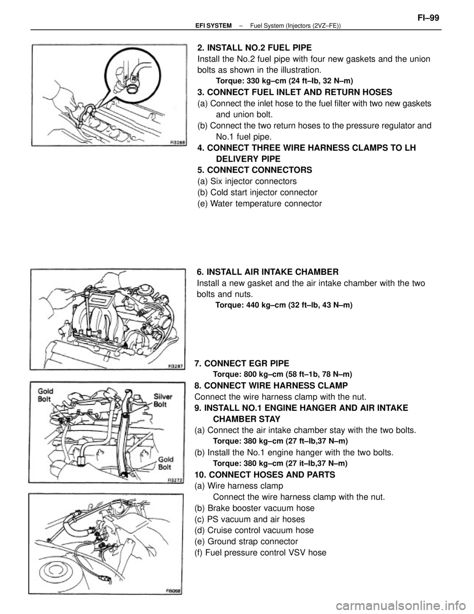
7. CONNECT EGR PIPE
Torque: 800 kg±cm (58 ft±1b, 78 N±m)
8. CONNECT WIRE HARNESS CLAMP
Connect the wire harness clamp with the nut.
9. INSTALL NO.1 ENGINE HANGER AND AIR INTAKE
CHAMBER STAY
(a) Connect the air intake chamber stay with the two bolts.
Torque: 380 kg±cm (27 ft±Ib,37 N±m)
(b) Install the No.1 engine hanger with the two bolts.
Torque: 380 kg±cm (27 it±Ib,37 N±m)
10. CONNECT HOSES AND PARTS
(a) Wire harness clamp
Connect the wire harness clamp with the nut.
(b) Brake booster vacuum hose
(c) PS vacuum and air hoses
(d) Cruise control vacuum hose
(e) Ground strap connector
(f) Fuel pressure control VSV hose2. INSTALL NO.2 FUEL PIPE
Install the No.2 fuel pipe with four new gaskets and the union
bolts as shown in the illustration.
Torque: 330 kg±cm (24 ft±Ib, 32 N±m)
3. CONNECT FUEL INLET AND RETURN HOSES
(a) Connect the inlet hose to the fuel filter with two new gaskets
and union bolt.
(b) Connect the two return hoses to the pressure regulator and
No.1 fuel pipe.
4. CONNECT THREE WIRE HARNESS CLAMPS TO LH
DELIVERY PIPE
5. CONNECT CONNECTORS
(a) Six injector connectors
(b) Cold start injector connector
(e) Water temperature connector
6. INSTALL AIR INTAKE CHAMBER
Install a new gasket and the air intake chamber with the two
bolts and nuts.
Torque: 440 kg±cm (32 ft±lb, 43 N±m)
± EFI SYSTEMFuel System (Injectors (2VZ±FE))FI±99
Page 1148 of 2389
Voltage at ECU Wiring Connectors (3S±FE)
No trouble (ºCHECKº engine warning light off) and engine running
Stop light SW 4N (Brake pedal depressed) or defogger SW ONCheck connector TE1 ± E1 not connected
Check connector TE 1 ± E 1 connectedMeasuring plate fully closed
Ex. shift position P or N rangeIntake air temp. 20°C (68°F)
Coolant temp. 80°C (1 760F) Measuring plate fully open
Shift position P or N rangeThrottle valve fully closedThrottle valve fully closed
Heater blower SW ON Air conditioning ONThrottle valve open
Throttle valve open
Throttle valve open
Cranking or idlingIG SW ONSTD voltage (V) Condition
3,000 rpm
IG SW ONIG SW ON1G SW ON
IG SW ON Terminals
IG SW ON
CrankingIdling
± EFI SYSTEMElectronic Control System (Electronic Controlled Unit(ECU))
FI±133
Page 1149 of 2389
Voltage at ECU Wiring Connectors (2VZ±FE)
No trouble (ºCHECKº engine warning light off) and engine running
Stop light SW ON (Brake pedal depressed)Check connector TE1 ± E1 not connected
Check connector TE1 ± E1 connected
Ex. shift position P or N range Measuring plate fully closed
Intake air temp. 20°C (68°F)
Coolant temp. 80°C (176°F) Measuring plate fully open
Shift position P or N range Throttle valve fully closed
Heater blower SW ON Air conditioning ON Throttle valve open Throttle valve open
Cranking or idlingSm voltage (V)
3,000 rpm IG SW ON
IG SW ON
IG SW ON
IG SW ON
IG SW ON 1G SW ON Terminals
Cranking Idling
± EFI SYSTEMElectronic Control System (Electronic Controlled Unit(ECU))
FI±134
Page 1183 of 2389
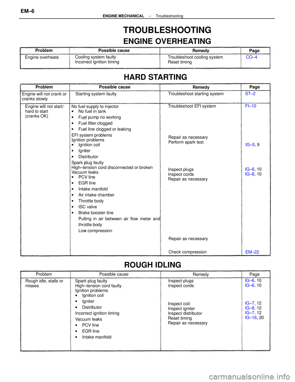
No fuel supply to injector
wNo fuel in tank
wFuel pump no working
wFuel filter clogged
wFuel line clogged or leaking
EFI system problems
Ignition problems
wIgnition coil
wIgniter
wDistributor
Spark plug faulty
High±tension cord disconnected or broken
Vacuum leaks
wPCV line
wEGR line
wIntake manifold
wAir intake chamber
wThrottle body
wISC valve
wBrake booster tine
Pulling in air between air flow meter and
throttle body
Low compression
Spark plug faulty
High±tension cord faulty
Ignition problems
wIgnition coil
wIgniter
wDistributor
Incorrect ignition timing
Vacuum leaks
wPCV line
wEGR line
wIntake manifold
TROUBLESHOOTING
ENGINE OVERHEATING
Inspect coil
Inspect igniter
Inspect distributor
Reset timing
Repair as necessaryInspect plugs
Inspect cords
Repair as necessary Troubleshoot cooling system
Reset timing
Engine will not start/
hard to start
(cranks OK)Cooling system faulty
Incorrect ignition timing
Repair as necessary
Perform spark test Engine will not crank or
cranks slowly
IG±7, 12
IG±8, 12
IG±7, 12
IG±16, 20 Rough idle, stalls or
misses
HARD STARTING
Troubleshoot starting system
Inspect plugs
Inspect cords Troubleshoot EFI system
ROUGH IDLING
Starting system faulty
Check compression Repair as necessary Engine overheats
IG±6, 10
IG±6, 10 IG±6, 10
IG±6, 10 Possible cause
Possible cause Possible cause
Remedy Remedy
Problem
Remedy Problem Problem
IG±5, 9
EM±22Page
Page
Page CO±4
FI±10 ST±2
± ENGINE MECHANICALTroubleshootingEM±6
Page 1184 of 2389
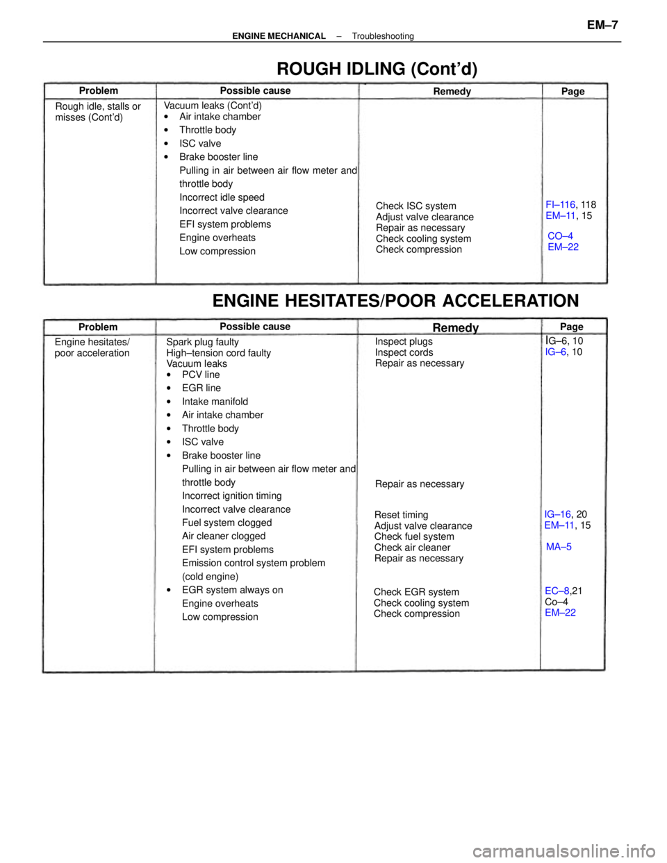
Spark plug faulty
High±tension cord faulty
Vacuum leaks
wPCV line
wEGR line
wIntake manifold
wAir intake chamber
wThrottle body
wISC valve
wBrake booster line
Pulling in air between air flow meter and
throttle body
Incorrect ignition timing
Incorrect valve clearance
Fuel system clogged
Air cleaner clogged
EFI system problems
Emission control system problem
(cold engine)
wEGR system always on
Engine overheats
Low compression Vacuum leaks (Cont'd)
wAir intake chamber
wThrottle body
wISC valve
wBrake booster line
Pulling in air between air flow meter and
throttle body
Incorrect idle speed
Incorrect valve clearance
EFI system problems
Engine overheats
Low compressionCheck ISC system
Adjust valve clearance
Repair as necessary
Check cooling system
Check compression
Reset timing
Adjust valve clearance
Check fuel system
Check air cleaner
Repair as necessary
ENGINE HESITATES/POOR ACCELERATION
Check EGR system
Check cooling system
Check compressionInspect plugs
Inspect cords
Repair as necessary
ROUGH IDLING (Cont'd)
Rough idle, stalls or
misses (Cont'd)
Engine hesitates/
poor acceleration
EC±8,21
Co±4
EM±22FI±116, 118
EM±11, 15
IG±16, 20
EM±11, 15 Repair as necessary
IG±6, 10
IG±6, 10 Possible causePossible cause
CO±4
EM±22 Remedy Problem
RemedyProblemPage
MA±5Page
± ENGINE MECHANICALTroubleshootingEM±7