Page 1407 of 2389
6. FILL TRANSAXLE WITH GEAR OIL OR FLUID
M/T (See page MT±1 17)
A/T Fluid type: ATF DEXRON) II
7. INSTALL ENGINE UNDER COVERS
8. INSTALL WHEELS
9. CHECK FRONT WHEEL ALIGNMENT
(See page FA ± 3) 5. INSTALL BEARING LOCK NUT, LOCK NUT CAP AND
COTTER PIN
(a) Torque the bearing lock nut while depressing the brake
pedal.
Torque: 1, 900 kg±cm (137 ft±Ib, 186 N±m )
(b) Install the lock nut cap and, using pliers, install a new
cotter pin. 4. CONNECT TIE ROD END TO STEERING KNUCKLE
Install and torque the nut, and secure it with a new cotter pin.
Torque: 500 kg±cm (36 ft±Ib, 49 N±m)
± FRONT AXLE AND SUSPENSIONFront Drive Shaft (4WD)FA±50
Page 1409 of 2389
REMOVAL OF FRONT SHOCK ABSORBER
ASSEMBLY
1. DISCONNECT BRAKE HOSE
(a) Remove union bolt, and disconnect the brake hose from
the disc brake caliper.
(b) Drain the brake fluid into a container.
3. REMOVE SHOCK ABSORBER FROM BODY
(a) Remove the three bolts holding the top of the suspen-
sion support.
(b) Remove the shock absorber from the body.
NOTICE: Cover the drive shaft boot with cloth to avoid
damaging it.
2. DISCONNECT STEERING KNUCKLE FROM SHOCK
ABSORBER
Remove the bolts and nuts, and disconnect the steer-
ing knuckle from the shock absorber.
4. CLAMP SHOCK ABSORBER IN VISE
Install a bolt and two nuts to the bracket at the lower portion of
the shock absorber shell and secure it in a vise. (c) Remove the clip from the brake hose bracket.
(d) Pull off the brake hose from the brake hose bracket.
± FRONT AXLE AND SUSPENSIONFront Shock AbsorberFA±52
Page 1412 of 2389
5. CONNECT BRAKE HOSE
(a) Run the brake hose through the brake hose bracket.
(b) Install the clip to the brake hose bracket. 4. INSTALL DUST COVER
Pack the bearing in the suspension support with MP
grease, and install the dust cover.
(c) Connect the brake hose with the union bolt and
new gaskets to the disc brake caliper.
Torque: 310 kg±cm (22 ft±Ib, 30 N ± m)
6. INSTALL CLIP
7. BLEED BRAKE LINE (See page BR±7)
8. INSPECT CAMBER (See page FA±4) HINT: When connecting the brake hose to the disc
brake caliper, connect so the peg aligns with the
hole.
± FRONT AXLE AND SUSPENSIONFront Shock AbsorberFA±55
Page 1857 of 2389
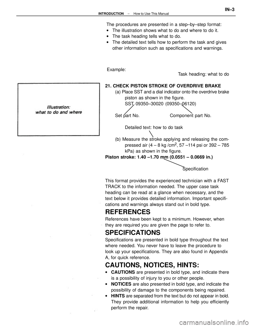
Task heading: what to do
21. CHECK PISTON STROKE OF OVERDRIVE BRAKE
(a) Place SST and a dial indicator onto the overdrive brake
piston as shown in the figure.
SST 09350±30020 (09350±06120)
Set part No. Component part No.
Detailed text: how to do task
(b) Measure the stroke applying and releasing the com-
pressed air (4 ± 8 kg /cm
2, 57 ±114 psi or 392 ± 785
kPa) as shown in the figure.
Piston stroke: 1.40 ±1.70 mm (0.0551 ± 0.0669 in.)
Specification
This format provides the experienced technician with a FAST
TRACK to the information needed. The upper case task
heading can be read at a glance when necessary, and the
text below it provides detailed information. Important specifi-
cations and warnings always stand out in bold type.
REFERENCES
References have been kept to a minimum. However, when
they are required you are given the page to refer to.
SPECIFICATIONS
Specifications are presented in bold type throughout the text
where needed. You never have to leave the procedure to
look up your specifications. They are also found in Appendix
A, for quick reference.
CAUTIONS, NOTICES, HINTS:
wCAUTIONS are presented in bold type, and indicate there
is a possibility of injury to you or other people.
wNOTICES are also presented in bold type, and indicate the
possibility of damage to the components being repaired.
wHINTS are separated from the text but do not appear in bold.
They provide additional information to help you efficiently
perform the repair. The procedures are presented in a step±by±step format:
wThe illustration shows what to do and where to do it.
wThe task heading tells what to do.
wThe detailed text tells how to perform the task and gives
other information such as specifications and warnings.
Example:
± INTRODUCTIONHow to Use This ManualIN±3
Page 1864 of 2389
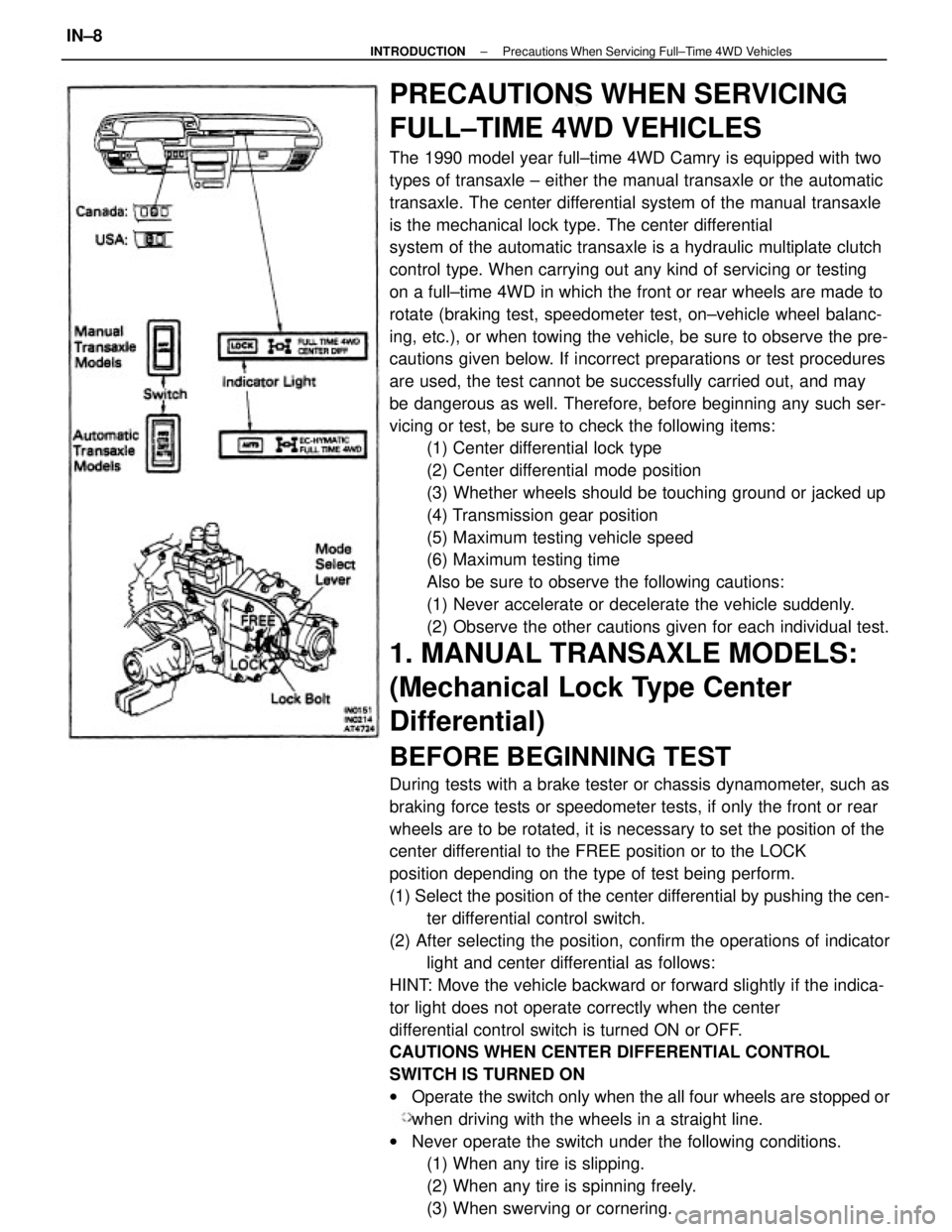
PRECAUTIONS WHEN SERVICING
FULL±TIME 4WD VEHICLES
The 1990 model year full±time 4WD Camry is equipped with two
types of transaxle ± either the manual transaxle or the automatic
transaxle. The center differential system of the manual transaxle
is the mechanical lock type. The center differential
system of the automatic transaxle is a hydraulic multiplate clutch
control type. When carrying out any kind of servicing or testing
on a full±time 4WD in which the front or rear wheels are made to
rotate (braking test, speedometer test, on±vehicle wheel balanc-
ing, etc.), or when towing the vehicle, be sure to observe the pre-
cautions given below. If incorrect preparations or test procedures
are used, the test cannot be successfully carried out, and may
be dangerous as well. Therefore, before beginning any such ser-
vicing or test, be sure to check the following items:
(1) Center differential lock type
(2) Center differential mode position
(3) Whether wheels should be touching ground or jacked up
(4) Transmission gear position
(5) Maximum testing vehicle speed
(6) Maximum testing time
Also be sure to observe the following cautions:
(1) Never accelerate or decelerate the vehicle suddenly.
(2) Observe the other cautions given for each individual test.
1. MANUAL TRANSAXLE MODELS:
(Mechanical Lock Type Center
Differential)
BEFORE BEGINNING TEST
During tests with a brake tester or chassis dynamometer, such as
braking force tests or speedometer tests, if only the front or rear
wheels are to be rotated, it is necessary to set the position of the
center differential to the FREE position or to the LOCK
position depending on the type of test being perform.
(1) Select the position of the center differential by pushing the cen-
ter differential control switch.
(2) After selecting the position, confirm the operations of indicator
light and center differential as follows:
HINT: Move the vehicle backward or forward slightly if the indica-
tor light does not operate correctly when the center
differential control switch is turned ON or OFF.
CAUTIONS WHEN CENTER DIFFERENTIAL CONTROL
SWITCH IS TURNED ON
wOperate the switch only when the all four wheels are stopped or
when driving with the wheels in a straight line.
wNever operate the switch under the following conditions.
(1) When any tire is slipping.
(2) When any tire is spinning freely.
(3) When swerving or cornering.
± INTRODUCTIONPrecautions When Servicing Full±Time 4WD VehiclesIN±8
Page 1865 of 2389
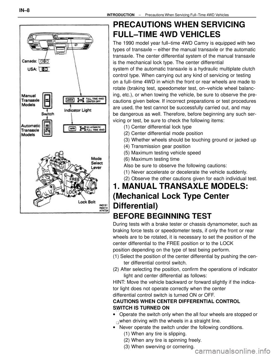
PRECAUTIONS WHEN SERVICING
FULL±TIME 4WD VEHICLES
The 1990 model year full±time 4WD Camry is equipped with two
types of transaxle ± either the manual transaxle or the automatic
transaxle. The center differential system of the manual transaxle
is the mechanical lock type. The center differential
system of the automatic transaxle is a hydraulic multiplate clutch
control type. When carrying out any kind of servicing or testing
on a full±time 4WD in which the front or rear wheels are made to
rotate (braking test, speedometer test, on±vehicle wheel balanc-
ing, etc.), or when towing the vehicle, be sure to observe the pre-
cautions given below. If incorrect preparations or test procedures
are used, the test cannot be successfully carried out, and may
be dangerous as well. Therefore, before beginning any such ser-
vicing or test, be sure to check the following items:
(1) Center differential lock type
(2) Center differential mode position
(3) Whether wheels should be touching ground or jacked up
(4) Transmission gear position
(5) Maximum testing vehicle speed
(6) Maximum testing time
Also be sure to observe the following cautions:
(1) Never accelerate or decelerate the vehicle suddenly.
(2) Observe the other cautions given for each individual test.
1. MANUAL TRANSAXLE MODELS:
(Mechanical Lock Type Center
Differential)
BEFORE BEGINNING TEST
During tests with a brake tester or chassis dynamometer, such as
braking force tests or speedometer tests, if only the front or rear
wheels are to be rotated, it is necessary to set the position of the
center differential to the FREE position or to the LOCK
position depending on the type of test being perform.
(1) Select the position of the center differential by pushing the cen-
ter differential control switch.
(2) After selecting the position, confirm the operations of indicator
light and center differential as follows:
HINT: Move the vehicle backward or forward slightly if the indica-
tor light does not operate correctly when the center
differential control switch is turned ON or OFF.
CAUTIONS WHEN CENTER DIFFERENTIAL CONTROL
SWITCH IS TURNED ON
wOperate the switch only when the all four wheels are stopped or
when driving with the wheels in a straight line.
wNever operate the switch under the following conditions.
(1) When any tire is slipping.
(2) When any tire is spinning freely.
(3) When swerving or cornering.
± INTRODUCTIONPrecautions When Servicing Full±Time 4WD VehiclesIN±8
Page 1866 of 2389
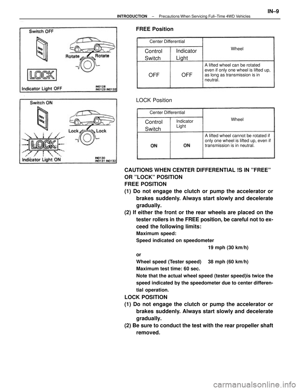
CAUTIONS WHEN CENTER DIFFERENTIAL !S IN ºFREEº
OR ºLOCKº POSITION
FREE POSITION
(1) Do not engage the clutch or pump the accelerator or
brakes suddenly. Always start slowly and decelerate
gradually.
(2) If either the front or the rear wheels are placed on the
tester rollers in the FREE position, be careful not to ex-
ceed the following limits:
Maximum speed:
Speed indicated on speedometer
19 mph (30 km/h)
or
Wheel speed (Tester speed) 38 mph (60 km/h)
Maximum test time: 60 sec.
Note that the actual wheel speed (tester speed)is twice the
speed indicated by the speedometer due to center differen-
tial operation.
LOCK POSITION
(1) Do not engage the clutch or pump the accelerator or
brakes suddenly. Always start slowly and decelerate
gradually.
(2) Be sure to conduct the test with the rear propeller shaft
removed.
A lifted wheel can be rotated
even if only one wheel is lifted up,
as long as transmission is in
neutral.
A lifted wheel cannot be rotated if
only one wheel is lifted up, even if
transmission is in neutral.
LOCK Position
Center Differential
Center Differential
Indicator
Light
Indicator
Light
FREE Position
Control
Switch Control
Switch
Wheel Wheel
OFFOFF
± INTRODUCTIONPrecautions When Servicing Full±Time 4WD VehiclesIN±9
Page 1867 of 2389
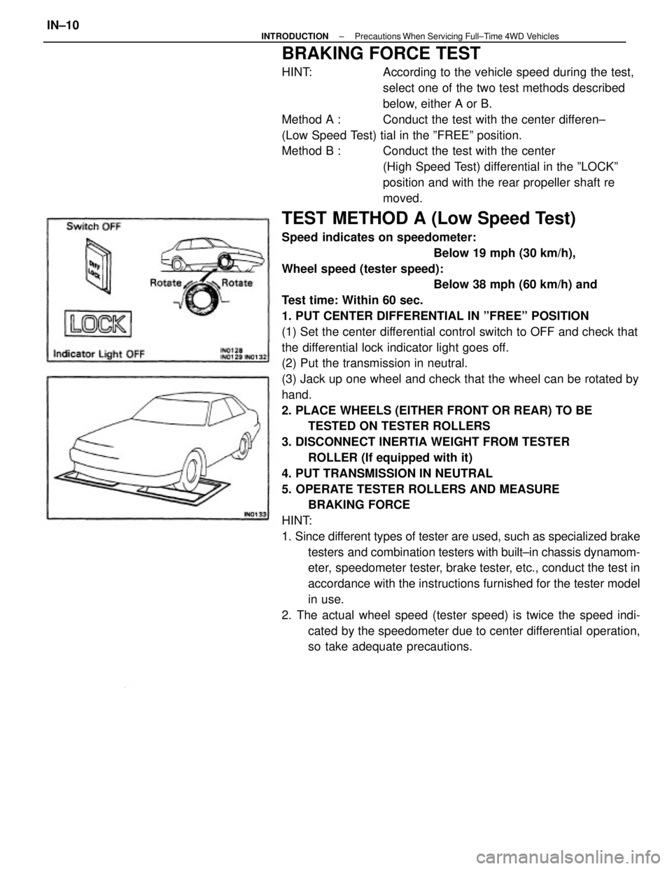
BRAKING FORCE TEST
HINT: According to the vehicle speed during the test,
select one of the two test methods described
below, either A or B.
Method A : Conduct the test with the center differen±
(Low Speed Test) tial in the ºFREEº position.
Method B : Conduct the test with the center
(High Speed Test) differential in the ºLOCKº
position and with the rear propeller shaft re
moved.
TEST METHOD A (Low Speed Test)
Speed indicates on speedometer:
Below 19 mph (30 km/h),
Wheel speed (tester speed):
Below 38 mph (60 km/h) and
Test time: Within 60 sec.
1. PUT CENTER DIFFERENTIAL IN ºFREEº POSITION
(1) Set the center differential control switch to OFF and check that
the differential lock indicator light goes off.
(2) Put the transmission in neutral.
(3) Jack up one wheel and check that the wheel can be rotated by
hand.
2. PLACE WHEELS (EITHER FRONT OR REAR) TO BE
TESTED ON TESTER ROLLERS
3. DISCONNECT INERTIA WEIGHT FROM TESTER
ROLLER (If equipped with it)
4. PUT TRANSMISSION IN NEUTRAL
5. OPERATE TESTER ROLLERS AND MEASURE
BRAKING FORCE
HINT:
1. Since different types of tester are used, such as specialized brake
testers and combination testers with built±in chassis dynamom-
eter, speedometer tester, brake tester, etc., conduct the test in
accordance with the instructions furnished for the tester model
in use.
2. The actual wheel speed (tester speed) is twice the speed indi-
cated by the speedometer due to center differential operation,
so take adequate precautions.
± INTRODUCTIONPrecautions When Servicing Full±Time 4WD VehiclesIN±10