Page 1915 of 2389

18. ACCELERATOR PEDAL
Check the pedal for smooth operation and uneven
pedal effort or catching.
19. CLUTCH PEDAL (See page CL±3)
Check the pedal for smooth operation.
Check that the pedal has the proper freeplay.
20. BRAKE PEDAL (See page BR±6)
(a) Check the pedal for smooth operation.
(b) Check that the pedal has the proper reserve
distance and freeplay.
(c) Check the brake booster function.
21. BRAKES
At a safe place, check that the brakes do not pull
to one side when applied.
22. PARKING BRAKE (See page BR±8)
(a) Check that the lever has the proper travel.
(b) On a safe incline, check that the vehicle is
held securely with only the parking brake
applied.
23. AUTOMATIC TRANSMISSION PARK
MECHANISM
(a) Check the lock release button of the selector
lever for proper and smooth operation.
(b) On a safe incline, check that vehicle is held
securely with the selector lever in the ºPº
position and all brakes released.
UNDER HOOD
24. WINDSHIELD WASHER FLUID
Check that there is sufficient fluid in the tank.
25. ENGINE COOLANT LEVEL
Check that the coolant level is between the
ºFULLº and ºLOWº lines on the see±through reser-
voir.
26. RADIATOR AND HOSES
(a) Check that the front of the radiator is clean
and not blocked with leaves, dirt or bugs.
(b) Check the hoses for cracks, kinks, rot or
loose connections.
27. BATTERY ELECTROLYTE LEVEL
Check that the electrolyte level of all battery cells
is between the upper and lower level lines on the
case. If level is low, add distilled water only.28. BRAKE AND CLUTCH FLUID LEVELS
(a) Check that the brake fluid level is near the
upper level line on the see±through reser-
voir.
(b) Check that the clutch fluid level is within
+ 5 mm (0.20 in.) of the reservoir hem.
29. ENGINE DRIVE BELTS
Check all drive belts for fraying, cracks, wear or
oiliness.
30. ENGINE OIL LEVEL
Check the level on the dipstick with the engine
turned off.
31. POWER STEERING FLUID LEVEL
Check the level.
The level should be in the ºHOTº or ºCOLDº
range depending on the fluid temperature.
32. AUTOMATIC TRANSMISSION FLUID
LEVEL
(a) Park the vehicle on a level surface.
(b) With the engine idling and the parking
brake applied, shift the selector into all
positions from ºPº to ºLº, and then shift
into ºPº.
(c) Pull out the dipstick and wipe off the fluid
with a clean rag. Re±insert the dipstick
and check that the fluid level is in the HOT
range.
(d) Perform this check with the fluid at normal
driving temperature (70 ± 80
°C or
158 ± 176°F).
NOTE: Wait about 30 minutes before check-
ing the fluid level after extended driving at high
speeds i n hot weather, driving i n heavy traffic
or with a trailer.
33. EXHAUST SYSTEM
Visually inspect for cracks, holes or loose sup-
ports.
If any change in the sound of the exhaust oK
smell of the exhaust fumes is noticed, have the
cause located and corrected.
± MAINTENANCEGeneral MaintenanceMA±17
Page 1919 of 2389

BRAKES
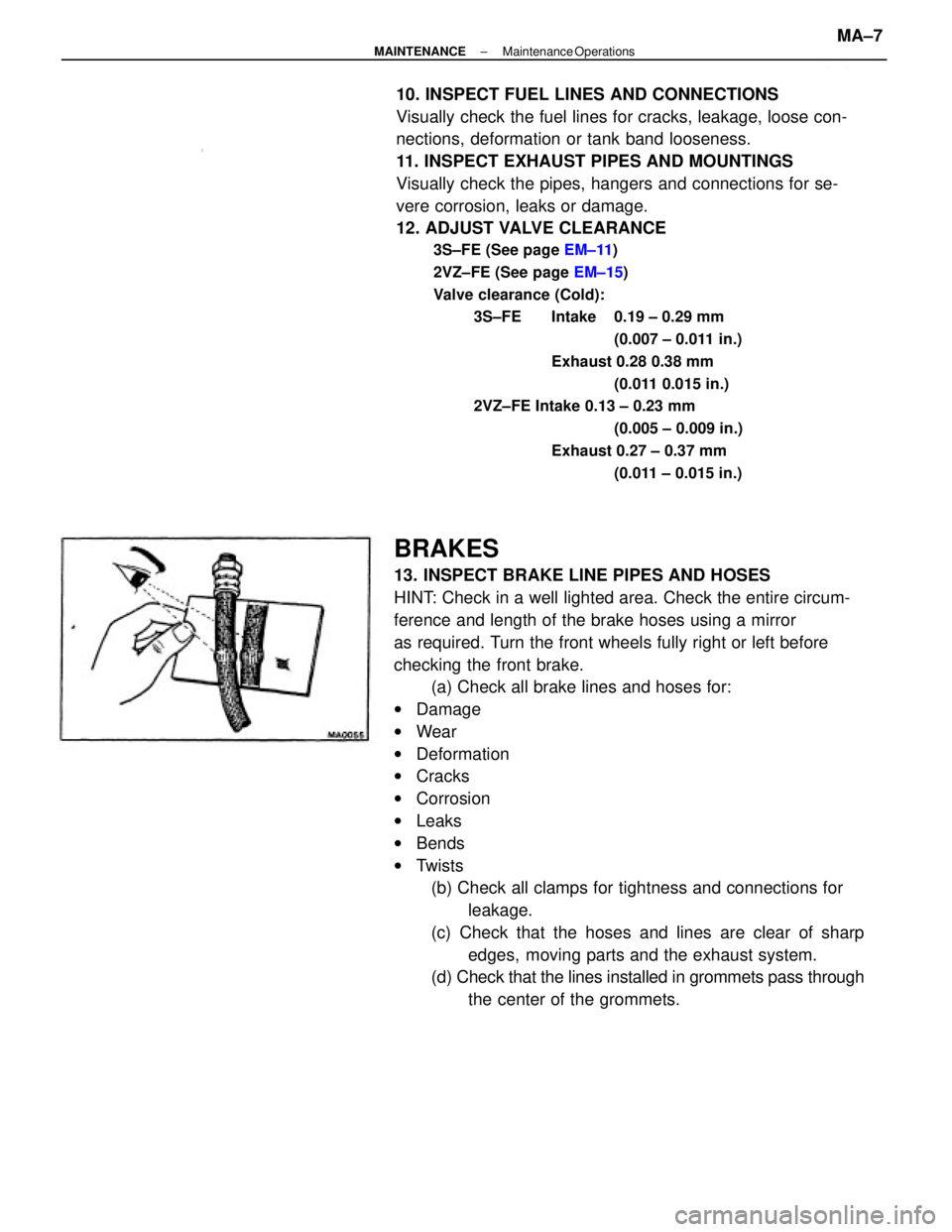
13. INSPECT BRAKE LINE PIPES AND HOSES
HINT: Check in a well lighted area. Check the entire circum-
ference and length of the brake hoses using a mirror
as required. Turn the front wheels fully right or left before
checking the front brake.
(a) Check all brake lines and hoses for:
wDamage
wWear
wDeformation
wCracks
wCorrosion
wLeaks
wBends
wTwists
(b) Check all clamps for tightness and connections for
leakage.
(c) Check that the hoses and lines are clear of sharp
edges, moving parts and the exhaust system.
(d) Check that the lines installed in grommets pass through
the center of the grommets. 10. INSPECT FUEL LINES AND CONNECTIONS
Visually check the fuel lines for cracks, leakage, loose con-
nections, deformation or tank band looseness.
11. INSPECT EXHAUST PIPES AND MOUNTINGS
Visually check the pipes, hangers and connections for se-
vere corrosion, leaks or damage.
12. ADJUST VALVE CLEARANCE
3S±FE (See page EM±11)
2VZ±FE (See page EM±15)
Valve clearance (Cold):
3S±FE Intake 0.19 ± 0.29 mm
(0.007 ± 0.011 in.)
Exhaust 0.28 0.38 mm
(0.011 0.015 in.)
2VZ±FE Intake 0.13 ± 0.23 mm
(0.005 ± 0.009 in.)
Exhaust 0.27 ± 0.37 mm
(0.011 ± 0.015 in.)
± MAINTENANCEMaintenance OperationsMA±7
Page 1920 of 2389

(d) Settle the parking brake shoes and drum. When per-
forming the road test in item 23, do the following:
wDrive the vehicle at approx. 50 km/h (30 mph) on a safe, lev-
el and dry road.
wWith the parking brake release button pushed in, pull on the
lever with 9 kg (20 Ib, 88 N) of force.
wDrive the vehicle for approx. m (1 /4 mile) in this condition.
wRepeat this procedure 2 or 3 times.
wCheck parking lever travel.
If necessary, adjust the parking brake.
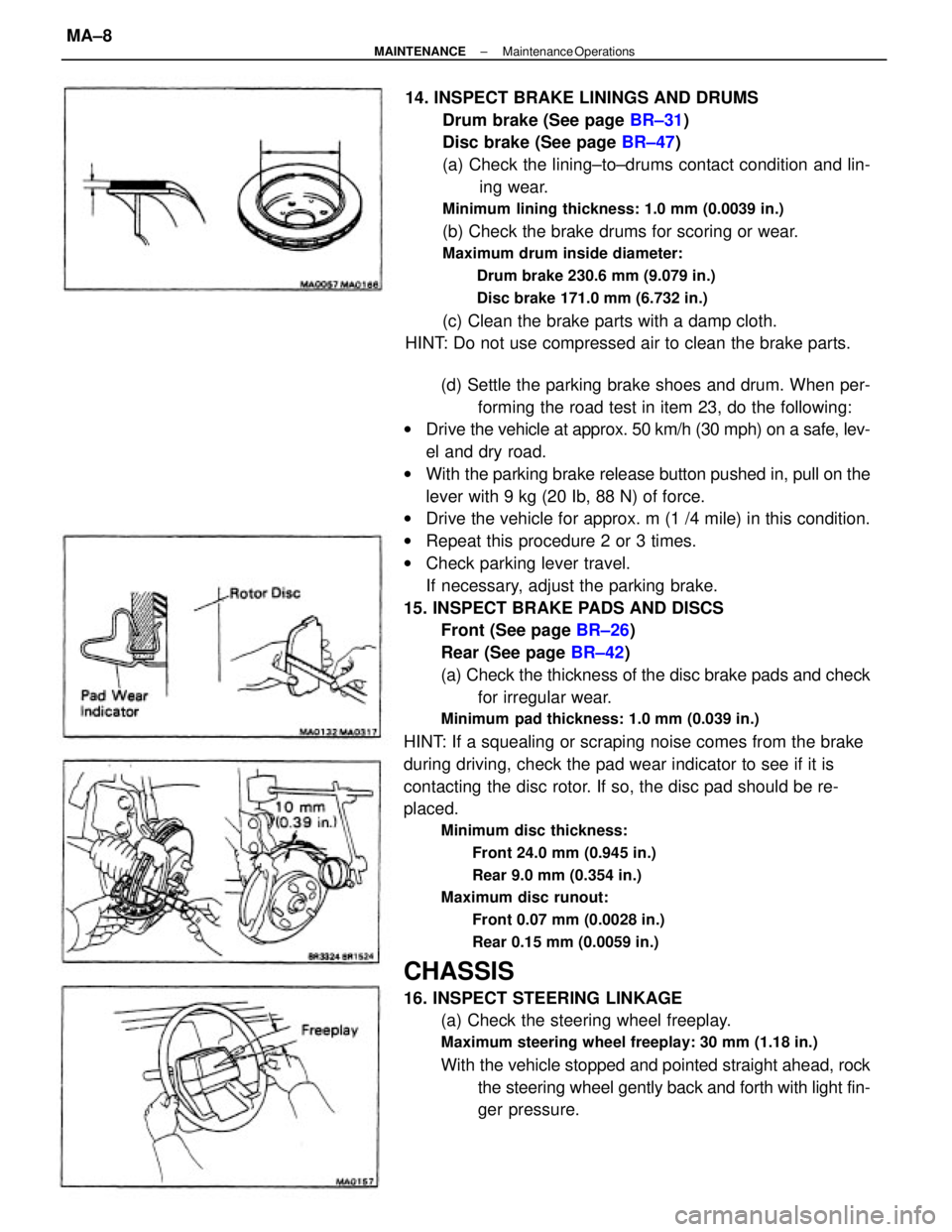
15. INSPECT BRAKE PADS AND DISCS
Front (See page BR±26)
Rear (See page BR±42)
(a) Check the thickness of the disc brake pads and check
for irregular wear.
Minimum pad thickness: 1.0 mm (0.039 in.)
HINT: If a squealing or scraping noise comes from the brake
during driving, check the pad wear indicator to see if it is
contacting the disc rotor. If so, the disc pad should be re-
placed.
Minimum disc thickness:
Front 24.0 mm (0.945 in.)
Rear 9.0 mm (0.354 in.)
Maximum disc runout:
Front 0.07 mm (0.0028 in.)
Rear 0.15 mm (0.0059 in.)
CHASSIS
16. INSPECT STEERING LINKAGE
(a) Check the steering wheel freeplay.
Maximum steering wheel freeplay: 30 mm (1.18 in.)
With the vehicle stopped and pointed straight ahead, rock
the steering wheel gently back and forth with light fin-
ger pressure. 14. INSPECT BRAKE LININGS AND DRUMS
Drum brake (See page BR±31)
Disc brake (See page BR±47)
(a) Check the lining±to±drums contact condition and lin-
ing wear.
Minimum lining thickness: 1.0 mm (0.0039 in.)
(b) Check the brake drums for scoring or wear.
Maximum drum inside diameter:
Drum brake 230.6 mm (9.079 in.)
Disc brake 171.0 mm (6.732 in.)
(c) Clean the brake parts with a damp cloth.
HINT: Do not use compressed air to clean the brake parts.
± MAINTENANCEMaintenance OperationsMA±8
Page 1927 of 2389

23. FINAL INSPECTION
(a) Check the operation of the body parts:
wHood
Auxiliary catch operation properly
Hood locks securely when closed
wFront and rear doors
Door locks operate properly
Doors close properly
wLuggage compartment door and back door
Door sock operates properly
wSeats
Seat adjusts easily and locks securely in any position
Front seat back locks securely in any position
Folding±down rear seat backs lock securely
(b) Road test
wCheck the engine and chassis for abnormal noises.
wCheck that the vehicle does not wander or pull to one side.
wCheck that the brakes work properly and do not drag.
wPerform bedding down of the parking brake shoes and drum.
(See page MA±8)
(c) Be sure to deliver a clean car especially check:
wSteering wheel
wShift lever knob
wAll switch knobs
wDoor handles
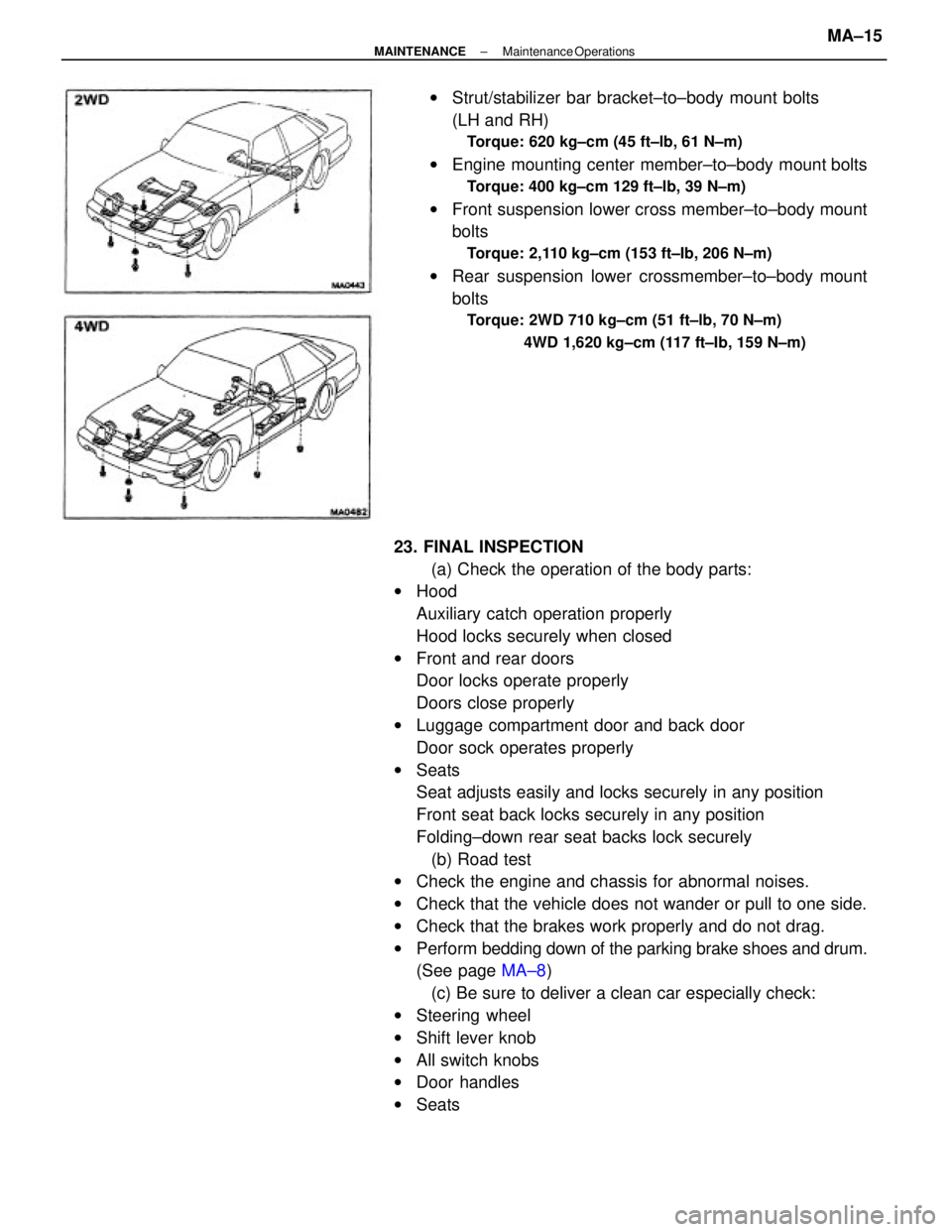
wSeatswStrut/stabilizer bar bracket±to±body mount bolts
(LH and RH)
Torque: 620 kg±cm (45 ft±lb, 61 N±m)
wEngine mounting center member±to±body mount bolts
Torque: 400 kg±cm 129 ft±lb, 39 N±m)
wFront suspension lower cross member±to±body mount
bolts
Torque: 2,110 kg±cm (153 ft±Ib, 206 N±m)
wRear suspension lower crossmember±to±body mount
bolts
Torque: 2WD 710 kg±cm (51 ft±lb, 70 N±m)
4WD 1,620 kg±cm (117 ft±Ib, 159 N±m)
± MAINTENANCEMaintenance OperationsMA±15
Page 1933 of 2389
16. DISCONNECT LEFT STEERING KNUCKLE FROM
LOWER ARM
(a) Disconnect the steering knuckle from the tower arm.
(b) Pull the steering knuckle toward the outside and remove
the drive shaft.
17. REMOVE STABILIZER BAR
(See page FA±34) 15. REMOVE CENTER DRIVE SHAFT
(a) Using pliers, remove the snap ring from the bearing
bracket.
(b) Remove the bolt on the bearing bracket.
(c) Pull out the center drive shaft. 13. REMOVE ENGINE MOUNTING CENTER MEMBER
(a) Remove the front and rear engine mounting bolts.
(b) Remove the engine mounting center member.
14. DISCONNECT BOTH DRIVE SHAFTS
Loosen the six nuts while depressing the brake pedal. 12. REMOVE SUSPENSION LOWER CROSSMEMBER
± MANUAL TRANSAXLES51 Transmission.MT±5
Page 1952 of 2389
INSTALLATION OF TRANSAXLE
1. INSTALL TRANSAXLE TO ENGINE
Align the input shaft spline with the clutch disc, and
install the transaxle to the engine. Torque the bolts.
Torque:
12 mm bolt 650 kg±cm (47 ft±lb, 64 N±m)
10 mm bolt 470 kg±cm (34 ft±Ib, 46 N±m)
2. CONNECT LEFT ENGINE MOUNTING
Connect the left engine mounting with the bolts. Torque
the bolts.
Torque: 530 kg±cm (38 ft±lb, 52 N±rm)
3. INSTALL STABILIZER BAR
(See page FA±35)
4. INSTALL CENTER DRIVE SHAFT
(a) Insert the center drive shaft to the transaxle through the
bearing bracket.
(b) Secure the center drive shaft with the snap ring.
(c) Tighten a new bolt on the bearing bracket.
Torque: 330 kg±cm (24 ft±lb, 32 N±m)
5. CONNECT BOTH DRIVE SHAFTS
Connect the drive shaft and torque the six nuts while de-
pressing the brake pedal.
Torque: 370 kg±cm (27 ft±Ib, 36 N±m)
6. CONNECT LEFT STEERING KNUCKLE TO LOWER
ARM
Torque: 1,150 kg±cm (83 ft±Ib, 113 N±m)
± MANUAL TRANSAXLES51 TransmissionMT±38
Page 2139 of 2389
2. LOOSEN CROSS GROOVE JOINT SET BOLTS
(a) Depress the brake pedal and hold it.
(b) Using a SST, loosen the cross groove joint set bolts
1 /2 turn.
SST 09313±30021
HINT: Put a piece of cloth or an equivalent into the inside of
the universal joint cover.
REMOVAL OF PROPELLER SHAFT
1. DISCONNECT FRONT PROPELLER SHAFT
(a) Place the matchmarks on the both flanges.
(b) Remove the four bolts, washers and nuts.
3. REMOVE INTERMEDIATE SHAFT AND REAR
PROPELLER SHAFT
(a) Place the matchmarks on the both flanges.
(b) Remove the bolts, nuts and washers.
(e) Remove the two bolts, front center support bearing and
washers.
(d) Remove rear center support bearing and washers. (c) Pull the yoke from the transfer.
(d) Insert SST in the transfer to prevent oil leakage.
SST 09325±20010
± PROPELLER SHAFTPropeller ShaftPR±4
Page 2145 of 2389
2. INSTALL REAR PROPELLER SHAFT
(a) Align the matchrmarks on the flanges and connect the
shaft with the four bolts, washers and nuts.
(b)Torque the bolts and nuts.
Torque: 750 kg±cm (54 ft±lb, 74 N±m)
4. TIGHTEN CROSS GROOVE JOINT SET BOLTS
(a) Depress the brake pedal and hold it.
(b) Using SST, tighten the cross groove joint set bolts.
SST 09313±30021
Torque: 275 kg±cm (20 ft±Ib. 27 N±m)
INSTALLATION OF PROPELLER
SHAFT
1. INSTALL CENTER SUPPORT BEARING TEMPORARILY
3. INSTALL FRONT PROPELLER SHAFT
(a) Remove SST from the transfer.
SST 09325±20010
(b) Insert the yoke into the transfer.
(c) Align the matchmarks on the both flanges, then
install the bolts, washers and nuts.
Torque: 750 kg±cm (54 ft±lb, 74 N±m)
± PROPELLER SHAFTPropeller ShaftPR±10