Page 1240 of 2389
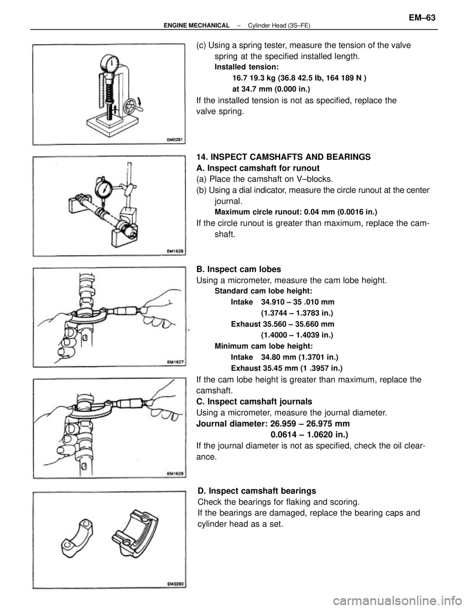
B. Inspect cam lobes
Using a micrometer, measure the cam lobe height.
Standard cam lobe height:
Intake 34.910 ± 35 .010 mm
(1.3744 ± 1.3783 in.)
Exhaust 35.560 ± 35.660 mm
(1.4000 ± 1.4039 in.)
Minimum cam lobe height:
Intake 34.80 mm (1.3701 in.)
Exhaust 35.45 mm (1 .3957 in.)
If the cam lobe height is greater than maximum, replace the
camshaft.
C. Inspect camshaft journals
Using a micrometer, measure the journal diameter.
Journal diameter: 26.959 ± 26.975 mm
0.0614 ± 1.0620 in.)
If the journal diameter is not as specified, check the oil clear-
ance. 14. INSPECT CAMSHAFTS AND BEARINGS
A. Inspect camshaft for runout
(a) Place the camshaft on V±blocks.
(b) Using a dial indicator, measure the circle runout at the center
journal.
Maximum circle runout: 0.04 mm (0.0016 in.)
If the circle runout is greater than maximum, replace the cam-
shaft. (c) Using a spring tester, measure the tension of the valve
spring at the specified installed length.
Installed tension:
16.7 19.3 kg (36.8 42.5 Ib, 164 189 N )
at 34.7 mm (0.000 in.)
If the installed tension is not as specified, replace the
valve spring.
D. Inspect camshaft bearings
Check the bearings for flaking and scoring.
If the bearings are damaged, replace the bearing caps and
cylinder head as a set.
± ENGINE MECHANICALCylinder Head (3S±FE)EM±63
Page 1243 of 2389
ASSEMBLY OF CYLINDER HEAD
(See page EM±48)
HINT:
wThoroughly clean all parts to be assembled.
wBefore installing the parts, apply new engine oil to all
sliding and rotating surfaces.
wReplace all gaskets and oil seals with new ones.
1. INSTALL VALVES
HINT: The intake valve oil seal is brown and the exhaust
valve oil seal is black.
(a) Install the following parts:
(1) Oil seal
(2) Valve
(3) Spring seat
(4) Valve spring
(5) Spring retainer
2. INSTALL VALVE LIFTERS AND SHIMS
(a) Install the valve lifter and shim.
(b) Check the valve lifter rotates smoothly by hand. (b) Using SST, compress the valve spring and place the
two keepers around the valve stem.
SST 09202±70010
(c) Using a plastic±faced hammer, lightly tap the valve
stem tip to assure proper fit.
± ENGINE MECHANICALCylinder Head (3S±FE)EM±66
Page 1244 of 2389
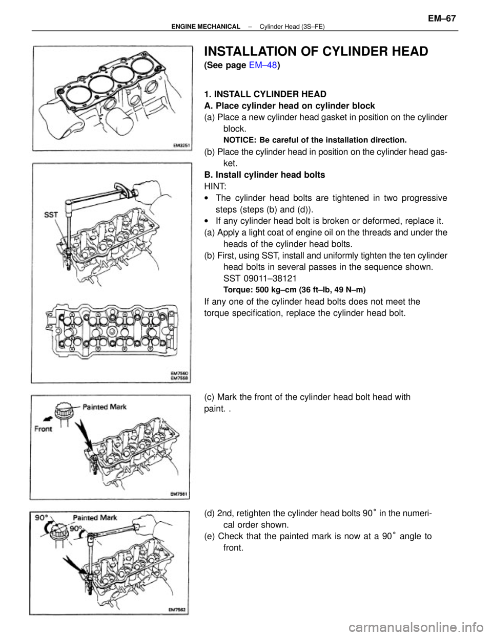
1. INSTALL CYLINDER HEAD
A. Place cylinder head on cylinder block
(a) Place a new cylinder head gasket in position on the cylinder
block.
NOTICE: Be careful of the installation direction.
(b) Place the cylinder head in position on the cylinder head gas-
ket.
B. Install cylinder head bolts
HINT:
wThe cylinder head bolts are tightened in two progressive
steps (steps (b) and (d)).
wIf any cylinder head bolt is broken or deformed, replace it.
(a) Apply a light coat of engine oil on the threads and under the
heads of the cylinder head bolts.
(b) First, using SST, install and uniformly tighten the ten cylinder
head bolts in several passes in the sequence shown.
SST 09011±38121
Torque: 500 kg±cm (36 ft±Ib, 49 N±m)
If any one of the cylinder head bolts does not meet the
torque specification, replace the cylinder head bolt.
(d) 2nd, retighten the cylinder head bolts 90° in the numeri-
cal order shown.
(e) Check that the painted mark is now at a 90° angle to
front.
INSTALLATION OF CYLINDER HEAD
(See page EM±48)
(c) Mark the front of the cylinder head bolt head with
paint. .
± ENGINE MECHANICALCylinder Head (3S±FE)EM±67
Page 1251 of 2389
26. INSTALL OIL PRESSURE SWITCH, ENGINE HANGERS
AND ALTERNATOR BRACKET
Torque the bolts.
Torque: 500 kg±cm (37 ft±Ib, 48 N±m)
27. INSTALL ALTERNATOR (See page CH±14)
28. INSTALL AIR CLEANER HOSE
29. INSTALL CRUISE CONTROL ACTUATOR
(See step 26 on page EM±137)
30. INSTALL RADIATOR RESERVOIR TANK
31. INSTALL ACCELERATOR CABLE, AND ADJUST IT
32. (A/T)
CONNECT THROTTLE CABLE, AND ADJUST IT
33. FILL WITH ENGINE COOLANT (See page CO±5)
Capacity (w/ Heater):
M/T 6.4 liters (6.8 US qts, 5.6 Imp. qts)
A/T (2WD) 6.3 liters (6.7 US qts, 5.5 Imp. qts)
A/T (4WD) 6.8 liters (7.2 US qts, 6.0 Imp. qts)
34. CONNECT CABLE TO NEGATIVE TERMINAL OF
BATTERY
35. START ENGINE AND CHECK FOR LEAKS
36. PERFORM ENGINE ADJUSTMENT
(a) Adjust the valve clearance. (See page EM±11)
Valve clearance (Cold):
Intake 0.19 ± 0.29 mm (0.007 ± 0.011 in.)
Exhaust 0.28 ± 0.38 mm (0.011 ± 0.015 in.)
(b) Adjust the ignition timing.
(See steps 7 to 10 on pages IG±16 and 17)
Ignition timing:
10° BTDC @ idle
(w/ Terminals TE 1 and E 1 connected)
37. CHECK TOE±IN (See page FA±5)
38. PERFORM ROAD TEST
Check for abnormal noise, shock, slippage, correct shift
points and smooth operation.
39. RECHECK ENGINE COOLANT LEVEL AND OIL LEVEL
± ENGINE MECHANICALCylinder Head (3S±FE)EM±74
Page 1268 of 2389
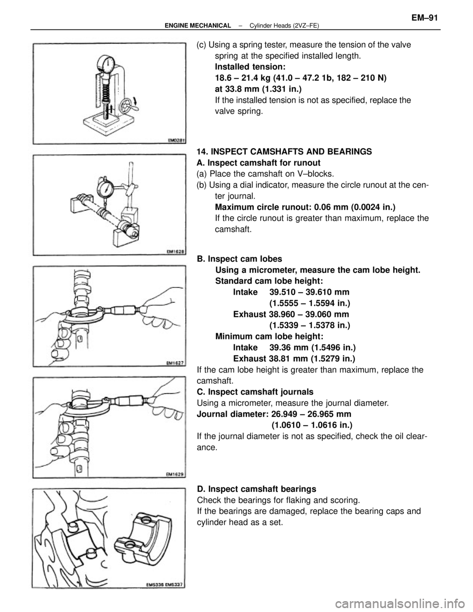
B. Inspect cam lobes
Using a micrometer, measure the cam lobe height.
Standard cam lobe height:
Intake 39.510 ± 39.610 mm
(1.5555 ± 1.5594 in.)
Exhaust 38.960 ± 39.060 mm
(1.5339 ± 1.5378 in.)
Minimum cam lobe height:
Intake 39.36 mm (1.5496 in.)
Exhaust 38.81 mm (1.5279 in.)
If the cam lobe height is greater than maximum, replace the
camshaft.
C. Inspect camshaft journals
Using a micrometer, measure the journal diameter.
Journal diameter: 26.949 ± 26.965 mm
(1.0610 ± 1.0616 in.)
If the journal diameter is not as specified, check the oil clear-
ance. 14. INSPECT CAMSHAFTS AND BEARINGS
A. Inspect camshaft for runout
(a) Place the camshaft on V±blocks.
(b) Using a dial indicator, measure the circle runout at the cen-
ter journal.
Maximum circle runout: 0.06 mm (0.0024 in.)
If the circle runout is greater than maximum, replace the
camshaft. (c) Using a spring tester, measure the tension of the valve
spring at the specified installed length.
Installed tension:
18.6 ± 21.4 kg (41.0 ± 47.2 1b, 182 ± 210 N)
at 33.8 mm (1.331 in.)
If the installed tension is not as specified, replace the
valve spring.
D. Inspect camshaft bearings
Check the bearings for flaking and scoring.
If the bearings are damaged, replace the bearing caps and
cylinder head as a set.
± ENGINE MECHANICALCylinder Heads (2VZ±FE)EM±91
Page 1273 of 2389
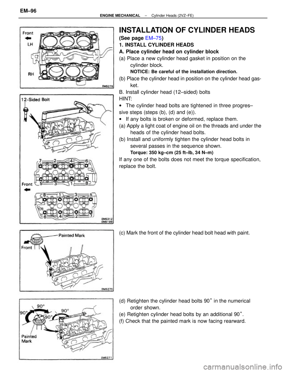
INSTALLATION OF CYLINDER HEADS
(See page EM±75)
1. INSTALL CYLINDER HEADS
A. Place cylinder head on cylinder block
(a) Place a new cylinder head gasket in position on the
cylinder block.
NOTICE: Be careful of the installation direction.
(b) Place the cylinder head in position on the cylinder head gas-
ket.
B. Install cylinder head (12±sided) bolts
HINT:
wThe cylinder head bolts are tightened in three progres±
sive steps (steps (b), (d) and (e)).
wIf any bolts is broken or deformed, replace them.
(a) Apply a light coat of engine oil on the threads and under the
heads of the cylinder head bolts.
(b) Install and uniformly tighten the cylinder head bolts in
several passes in the sequence shown.
Torque: 350 kg±cm (25 ft±lb, 34 N±m)
If any one of the bolts does not meet the torque specification,
replace the bolt.
(d) Retighten the cylinder head bolts 90° in the numerical
order shown.
(e) Retighten cylinder head bolts by an additional 90°.
(f) Check that the painted mark is now facing rearward. (c) Mark the front of the cylinder head bolt head with paint.
± ENGINE MECHANICALCylinder Heads (2VZ±FE)EM±96
Page 1278 of 2389
5. CHECK AND ADJUST VALVE CLEARANCE
(See page EM±9)
Turn the camshaft and position the cam lobe upward, check
and adjust the valve clearance.
Valve clearance (Cold):
Intake 0.13 ± 0.23 mm (0.005 ± 0.009 in.)
Exhaust 0.27 ± 0.37 mm (0.011 ± 0.015 in.) (e) Apply a light coat of engine oil on the threads and un-
der the heads of bearing cap bolts.
(f) Install and uniformly tighten the eight bearing cap bolts
in several passes in the sequence shown.
Torque: 160 kg±cm (12 ft±Ib, 16 N±m)
Remove the service bolt (6).
6. INSTALL CAMSHAFT OIL SEALS
(a) Apply MP grease to a new oil seal lip.
7. INSTALL SPARK PLUG TUBE GASKETS
Install the six tube gaskets. (b) Using SST, tap in the oil seals.
SST 09223±46011
± ENGINE MECHANICALCylinder Heads (2VZ±FE)EM±101
Page 1283 of 2389
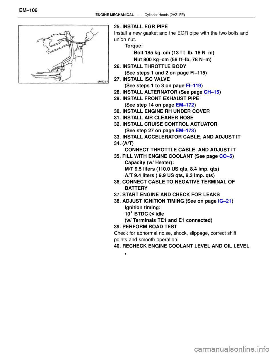
25. INSTALL EGR PIPE
Install a new gasket and the EGR pipe with the two bolts and
union nut.
Torque:
Bolt 185 kg±cm (13 f t±lb, 18 N±m)
Nut 800 kg±cm (58 ft±Ib, 78 N±m)
26. INSTALL THROTTLE BODY
(See steps 1 and 2 on page Fl±115)
27. INSTALL ISC VALVE
(See steps 1 to 3 on page FI±119)
28. INSTALL ALTERNATOR (See page CH±15)
29. INSTALL FRONT EXHAUST PIPE
(See step 14 on page EM±172)
30. INSTALL ENGINE RH UNDER COVER
31. INSTALL AIR CLEANER HOSE
32. INSTALL CRUISE CONTROL ACTUATOR
(See step 27 on page EM±173)
33. INSTALL ACCELERATOR CABLE, AND ADJUST IT
34. (A/T)
CONNECT THROTTLE CABLE, AND ADJUST IT
35. FILL WITH ENGINE COOLANT (See page CO±5)
Capacity (w/ Heater):
M/T 9.5 liters (110.0 US qts, 8.4 Imp. qts)
A/T 9.4 liters ( 9.9 US qts, 8.3 Imp. qts)
36. CONNECT CABLE TO NEGATIVE TERMINAL OF
BATTERY
37. START ENGINE AND CHECK FOR LEAKS
38. ADJUST IGNITION TIMING (See on page IG±21)
Ignition timing:
10° BTDC @ idle
(w/ Terminals TE1 and E1 connected)
39. PERFORM ROAD TEST
Check for abnormal noise, shock, slippage, correct shift
points and smooth operation.
40. RECHECK ENGINE COOLANT LEVEL AND OIL LEVEL
,
± ENGINE MECHANICALCylinder Heads (2VZ±FE)EM±106