Page 1333 of 2389
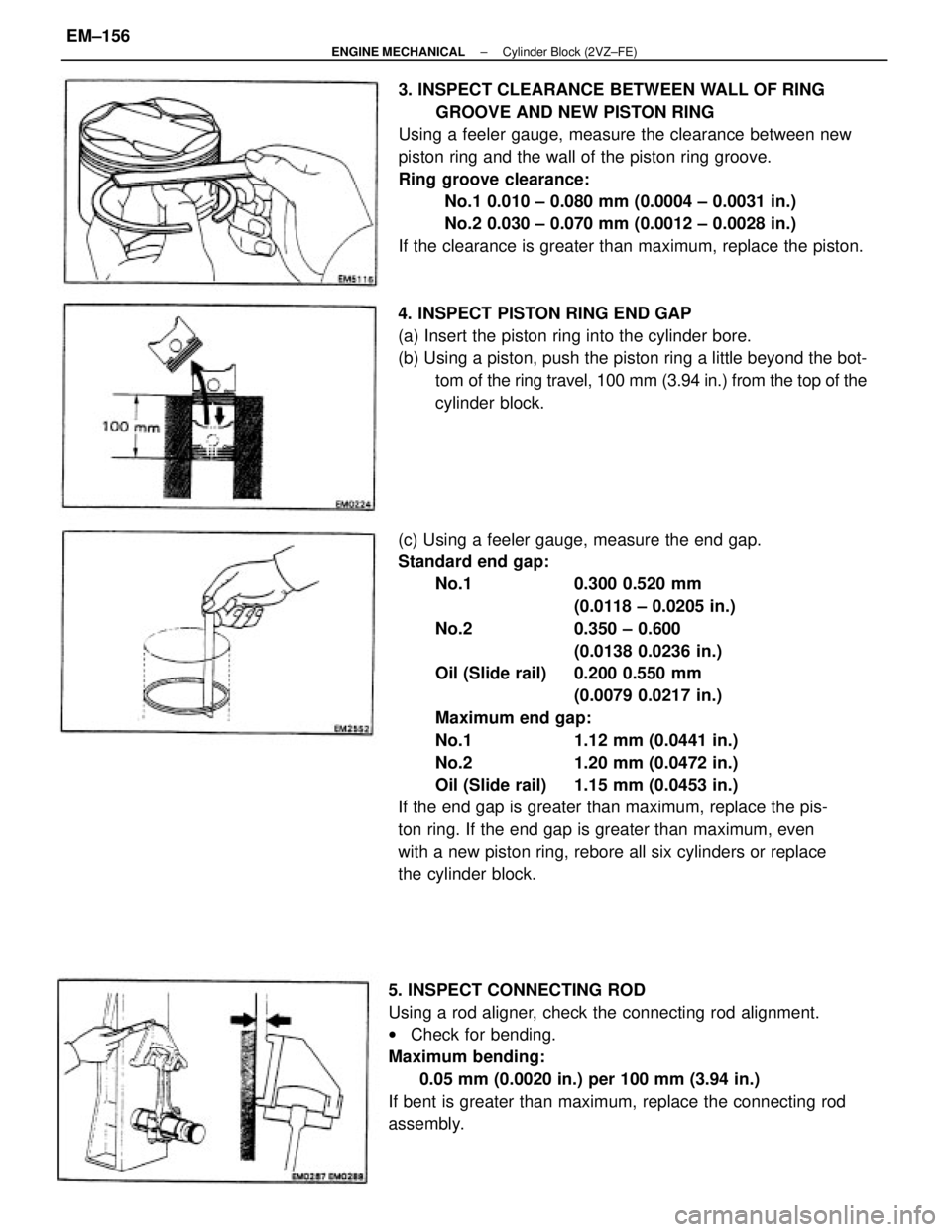
(c) Using a feeler gauge, measure the end gap.
Standard end gap:
No.1 0.300 0.520 mm
(0.0118 ± 0.0205 in.)
No.2 0.350 ± 0.600
(0.0138 0.0236 in.)
Oil (Slide rail) 0.200 0.550 mm
(0.0079 0.0217 in.)
Maximum end gap:
No.1 1.12 mm (0.0441 in.)
No.2 1.20 mm (0.0472 in.)
Oil (Slide rail) 1.15 mm (0.0453 in.)
If the end gap is greater than maximum, replace the pis-
ton ring. If the end gap is greater than maximum, even
with a new piston ring, rebore all six cylinders or replace
the cylinder block.3. INSPECT CLEARANCE BETWEEN WALL OF RING
GROOVE AND NEW PISTON RING
Using a feeler gauge, measure the clearance between new
piston ring and the wall of the piston ring groove.
Ring groove clearance:
No.1 0.010 ± 0.080 mm (0.0004 ± 0.0031 in.)
No.2 0.030 ± 0.070 mm (0.0012 ± 0.0028 in.)
If the clearance is greater than maximum, replace the piston.
5. INSPECT CONNECTING ROD
Using a rod aligner, check the connecting rod alignment.
wCheck for bending.
Maximum bending:
0.05 mm (0.0020 in.) per 100 mm (3.94 in.)
If bent is greater than maximum, replace the connecting rod
assembly.4. INSPECT PISTON RING END GAP
(a) Insert the piston ring into the cylinder bore.
(b) Using a piston, push the piston ring a little beyond the bot-
tom of the ring travel, 100 mm (3.94 in.) from the top of the
cylinder block.
± ENGINE MECHANICALCylinder Block (2VZ±FE)EM±156
Page 1336 of 2389
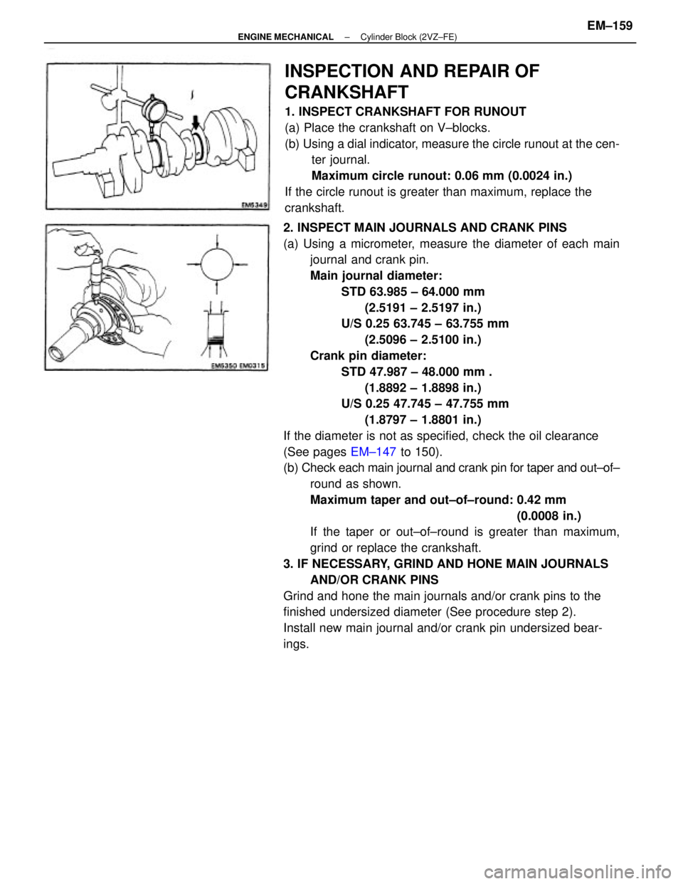
2. INSPECT MAIN JOURNALS AND CRANK PINS
(a) Using a micrometer, measure the diameter of each main
journal and crank pin.
Main journal diameter:
STD 63.985 ± 64.000 mm
(2.5191 ± 2.5197 in.)
U/S 0.25 63.745 ± 63.755 mm
(2.5096 ± 2.5100 in.)
Crank pin diameter:
STD 47.987 ± 48.000 mm .
(1.8892 ± 1.8898 in.)
U/S 0.25 47.745 ± 47.755 mm
(1.8797 ± 1.8801 in.)
If the diameter is not as specified, check the oil clearance
(See pages EM±147 to 150).
(b) Check each main journal and crank pin for taper and out±of±
round as shown.
Maximum taper and out±of±round: 0.42 mm
(0.0008 in.)
If the taper or out±of±round is greater than maximum,
grind or replace the crankshaft.
3. IF NECESSARY, GRIND AND HONE MAIN JOURNALS
AND/OR CRANK PINS
Grind and hone the main journals and/or crank pins to the
finished undersized diameter (See procedure step 2).
Install new main journal and/or crank pin undersized bear-
ings.
INSPECTION AND REPAIR OF
CRANKSHAFT
1. INSPECT CRANKSHAFT FOR RUNOUT
(a) Place the crankshaft on V±blocks.
(b) Using a dial indicator, measure the circle runout at the cen-
ter journal.
Maximum circle runout: 0.06 mm (0.0024 in.)
If the circle runout is greater than maximum, replace the
crankshaft.
± ENGINE MECHANICALCylinder Block (2VZ±FE)EM±159
Page 1339 of 2389
ASSEMBLY OF PISTON AND CONNECTING
ROD ASSEMBLIES
1. ASSEMBLE PISTON AND CONNECTING ROD
(a) Align the front marks of the piston and connecting rod.
Connecting rod front (mold) mark:
B6, 1 B, 8A, C3 or etc.
(b) Coat the piston pin and piston hole of the piston with
engine oil. .
(c) Using SST, press in the piston pin.
SST 09221±25024 (09221±00020, 09221±00030,
09221±00181, 09221±00190, 09221±00200)
(d) Check that the piston smoothly moves back and forth
on the piston pin.
(b) Using a piston ring expander, install the two com-
pression rings with the code mark facing upward.
Code mark: No.1 T or 1R
No.2 T2 or 2R 2. INSTALL PISTON RINGS
(a) Install the oil ring expander and two side rails by hand.
(c) Position the piston rings so that the ring ends are as
shown.
NOTICE: Do not align the ring ends.
± ENGINE MECHANICALCylinder Block (2VZ±FE)EM±162
Page 1341 of 2389
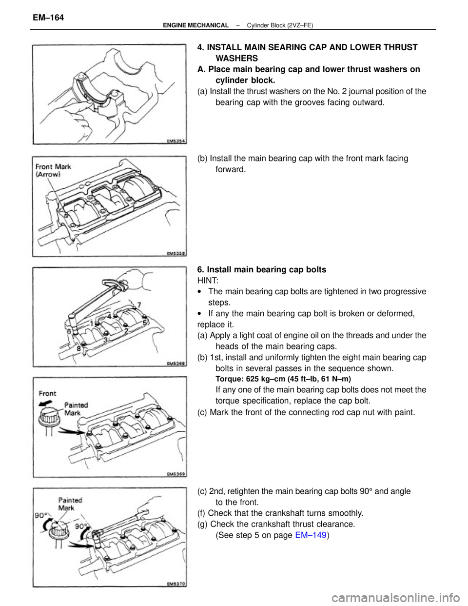
6. Install main bearing cap bolts
HINT:
wThe main bearing cap bolts are tightened in two progressive
steps.
wIf any the main bearing cap bolt is broken or deformed,
replace it.
(a) Apply a light coat of engine oil on the threads and under the
heads of the main bearing caps.
(b) 1st, install and uniformly tighten the eight main bearing cap
bolts in several passes in the sequence shown.
Torque: 625 kg±cm (45 ft±lb, 61 N±m)
If any one of the main bearing cap bolts does not meet the
torque specification, replace the cap bolt.
(c) Mark the front of the connecting rod cap nut with paint. 4. INSTALL MAIN SEARING CAP AND LOWER THRUST
WASHERS
A. Place main bearing cap and lower thrust washers on
cylinder block.
(a) Install the thrust washers on the No. 2 journal position of the
bearing cap with the grooves facing outward.
(c) 2nd, retighten the main bearing cap bolts 905 and angle
to the front.
(f) Check that the crankshaft turns smoothly.
(g) Check the crankshaft thrust clearance.
(See step 5 on page EM±149) (b) Install the main bearing cap with the front mark facing
forward.
± ENGINE MECHANICALCylinder Block (2VZ±FE)EM±164
Page 1343 of 2389
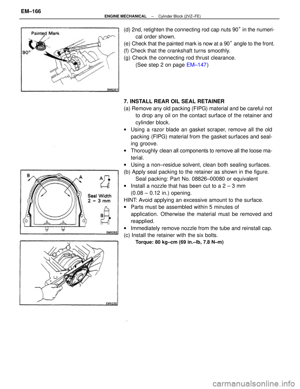
7. INSTALL REAR OIL SEAL RETAINER
(a) Remove any old packing (FIPG) material and be careful not
to drop any oil on the contact surface of the retainer and
cylinder block.
wUsing a razor blade an gasket scraper, remove all the old
packing (FIPG) material from the gasket surfaces and seal-
ing groove.
wThoroughly clean all components to remove all the loose ma-
terial.
wUsing a non±residue solvent, clean both sealing surfaces.
(b) Apply seal packing to the retainer as shown in the figure.
Seal packing: Part No. 08826±00080 or equivalent
wInstall a nozzle that has been cut to a 2 ± 3 mm
(0.08 ± 0.12 in.) opening.
HINT: Avoid applying an excessive amount to the surface.
wParts must be assembled within 5 minutes of
application. Otherwise the material must be removed and
reapplied.
wImmediately remove nozzle from the tube and reinstall cap.
(c) Install the retainer with the six bolts.
Torque: 80 kg±cm (69 in.±lb, 7.8 N±m)
(d) 2nd, retighten the connecting rod cap nuts 90° in the numeri-
cal order shown.
(e) Check that the painted mark is now at a 90° angle to the front.
(f) Check that the crankshaft turns smoothly.
(g) Check the connecting rod thrust clearance.
(See step 2 on page EM±147)
± ENGINE MECHANICALCylinder Block (2VZ±FE)EM±166
Page 1351 of 2389
28. (A/T)
INSTALL THROTTLE CABLE, AND ADJUST IT
29. INSTALL ACCELERATOR CABLE, AND ADJUST IT
30. INSTALL RADIATOR RESERVOIR TANK
31. INSTALL ALTERNATOR BELT ADJUSTING BAR
32. INSTALL ALTERNATOR (See page CH±15)
33. INSTALL RADIATOR (See page CO±20)
34. INSTALL IGNITION COIL, IGNITER AND BRACKET AS-
SEMBLY
(a) Install the ignition coil, igniter and bracket assembly with the
two bolts.
(b) Connect the following cord and connectors:
(1) Igniter connector
(2) Noise filter connector
(3) High±tension cord
35. INSTALL BATTERY
Connect the grand strap.
36. FILL WITH ENGINE COOLANT (See page CO±5)
Capacity (w/ Heater):
M /T 9.5 liters (10.0 US qts, 8.4 Imp. qts)
A/T 9.4 liters (9.9 US qts, 8.3 Imp. qts)
37. FILL WITH ENGINE OIL (See page LU±8)
Capacity:
Drain and refill
w/ Oil filter ±change
3.9 liters (4.1 US qts, 3.4 Imp. qts)
w/o Oil filter change
3.7 liters (3.9 US qts, 3.3 Imp. qts)
Dry fill 4.6 liters (4.8 US qts, 4.0 Imp. qts)
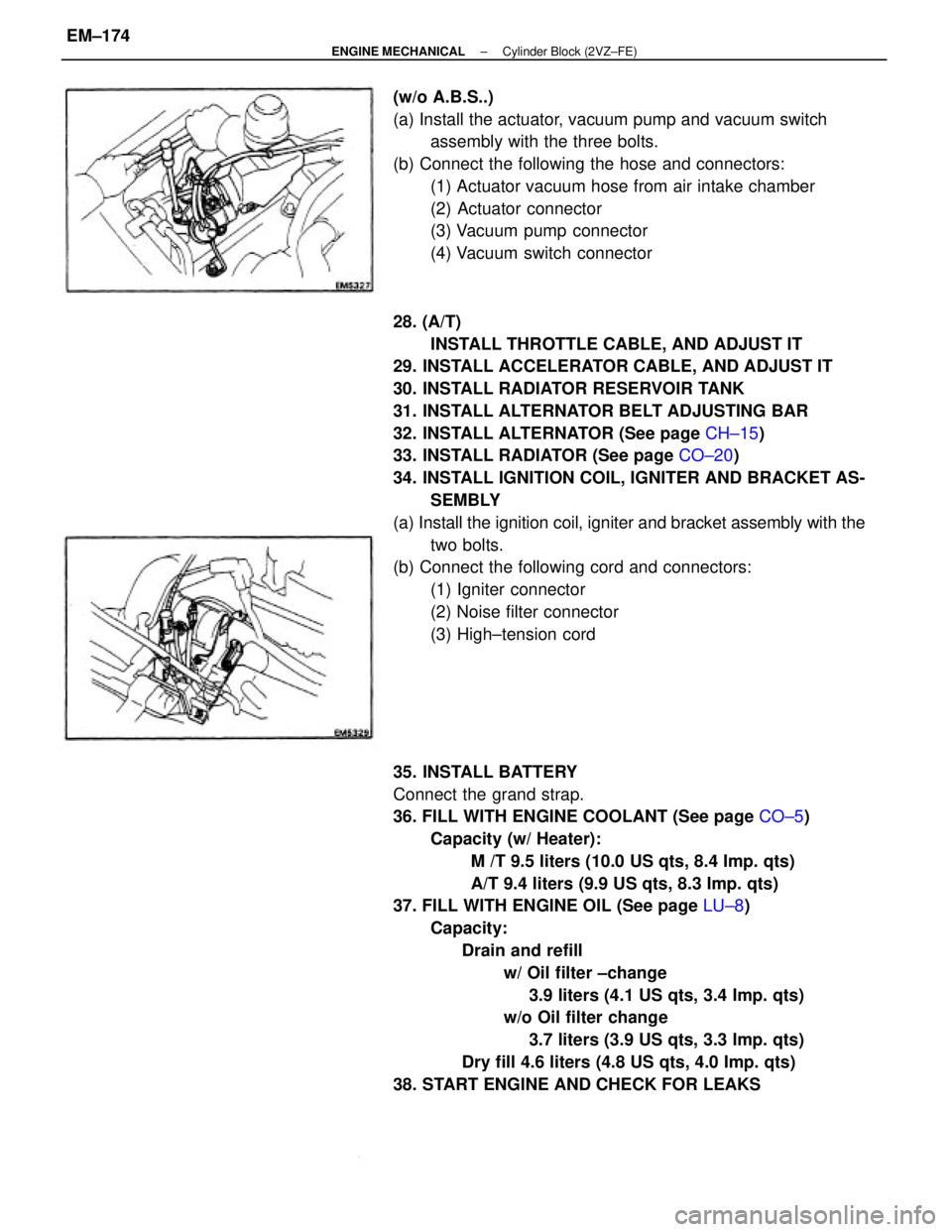
38. START ENGINE AND CHECK FOR LEAKS (w/o A.B.S..)
(a) Install the actuator, vacuum pump and vacuum switch
assembly with the three bolts.
(b) Connect the following the hose and connectors:
(1) Actuator vacuum hose from air intake chamber
(2) Actuator connector
(3) Vacuum pump connector
(4) Vacuum switch connector
± ENGINE MECHANICALCylinder Block (2VZ±FE)EM±174
Page 1352 of 2389
39. PERFORM ENGINE ADJUSTMENT
(a) Adjust the alternator drive belt.
(See page CH±3)
Drive belt tension: New belt 175 + 5 Ib
Used belt 115 + 20 Ib
(b) Adjust PS pump drive belt.
Drive belt tension: New belt 125 + 25 Ib
Used belt 80 + 20 lb
(c) Adjust the ignition timing.
(See page IG±21 )
Ignition timing:
10°BTDC @ idle
(w/ Terminals TE1 and E1 connected)
(d) Adjust the valve clearance.
Valve clearance:
Intake 0.13 ± 0.23 mm (0. 005 ± 0.009 in.)
Exhaust 0.27 ± 0.37 mm l0.011 ± 0.015 in.)
40. INSTALL HOOD
41. PERFORM ROAD TEST
Check for abnormal noise, shock, slippage, correct shift
points and smooth operation.
42. RECHECK ENGINE COOLANT AND ENGINE OIL
LEVELS
± ENGINE MECHANICALCylinder Block (2VZ±FE)EM±175
Page 1383 of 2389
INSTALLATION OF FRONT DRIVE
SHAFT
(See page FA±15)
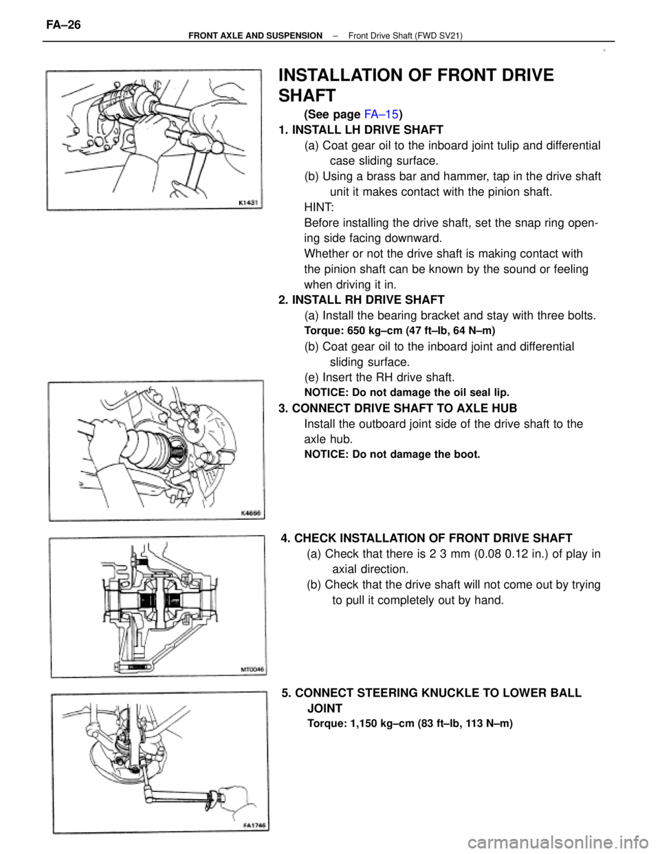
1. INSTALL LH DRIVE SHAFT
(a) Coat gear oil to the inboard joint tulip and differential
case sliding surface.
(b) Using a brass bar and hammer, tap in the drive shaft
unit it makes contact with the pinion shaft.
HINT:
Before installing the drive shaft, set the snap ring open-
ing side facing downward.
Whether or not the drive shaft is making contact with
the pinion shaft can be known by the sound or feeling
when driving it in.
2. INSTALL RH DRIVE SHAFT
(a) Install the bearing bracket and stay with three bolts.
Torque: 650 kg±cm (47 ft±Ib, 64 N±m)
(b) Coat gear oil to the inboard joint and differential
sliding surface.
(e) Insert the RH drive shaft.
NOTICE: Do not damage the oil seal lip.
3. CONNECT DRIVE SHAFT TO AXLE HUB
Install the outboard joint side of the drive shaft to the
axle hub.
NOTICE: Do not damage the boot.
4. CHECK INSTALLATION OF FRONT DRIVE SHAFT
(a) Check that there is 2 3 mm (0.08 0.12 in.) of play in
axial direction.
(b) Check that the drive shaft will not come out by trying
to pull it completely out by hand.
5. CONNECT STEERING KNUCKLE TO LOWER BALL
JOINT
Torque: 1,150 kg±cm (83 ft±Ib, 113 N±m)
± FRONT AXLE AND SUSPENSIONFront Drive Shaft (FWD SV21)FA±26