Page 1891 of 2389
3. REMOVE OIL PRESSURE SWITCH
4. INSTALL OIL PRESSURE GAUGE
5. WARM UP ENGINE
Allow the engine to normal operating temperature.
6. CHECK OIL PRESSURE
Oil pressure:
At idling 0.3 kg/cm
2 (4.3 pal, 29 kPa)
or more
At 3,000 rpm
3S±FE 2.5 ± 5.0 kg/cm
2
(36 ± 71 psi, 245 ± 490 kPa)
2vZ±FE 3.0 ± 5.5 kg/cm
2
(43 ± 78 psi, 294 ± 539 kPa)
7. REINSTALL OIL PRESSURE SWITCH
Apply adhesive to two or three threads.
Adhesive: Part No.08833±00080, THREE BOND
1344, LOCTITE 242 or equivalent
8. START ENGINE AND CHECK FOR LEAKS
OIL PRESSURE CHECK
1. CHECK ENGINE OIL QUALITY
Check the oil for deterioration, entry of water, discoloring
or thinning.
If the quality is poor, replace the oil.
Use API grade SG multigrade, fuel± efficient and recom-
mended viscosity oil.
2. CHECK ENGINE OIL LEVEL
The oil level should be between the ºLº and ºFº marks on the
dipstick.
If low, check for the leakage and add oil up to ºFº mark
± LUBRICATION SYSTEMOil Pressure CheckLU±6
Page 1892 of 2389
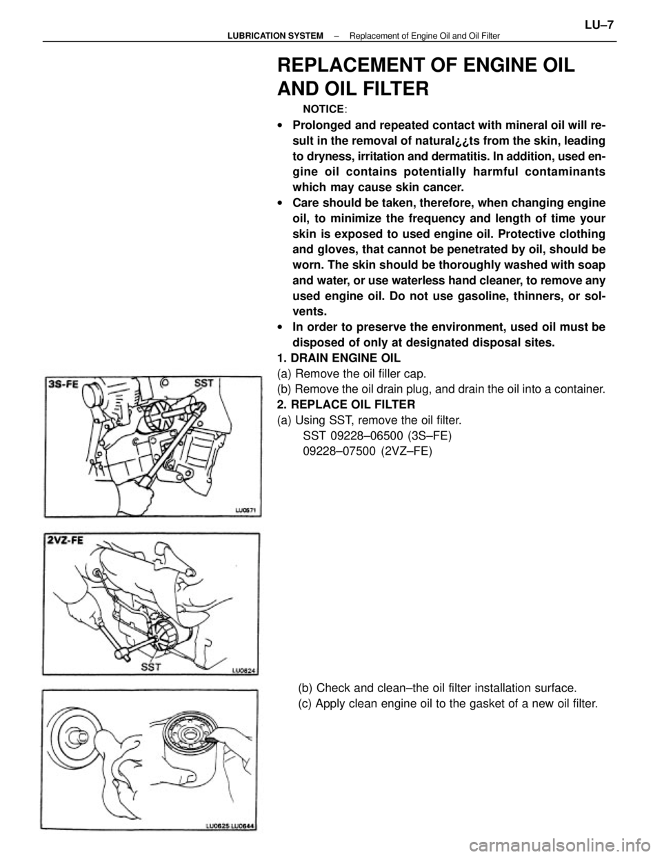
REPLACEMENT OF ENGINE OIL
AND OIL FILTER
NOTICE:
wProlonged and repeated contact with mineral oil will re-
sult in the removal of natural¿¿ts from the skin, leading
to dryness, irritation and dermatitis. In addition, used en-
gine oil contains potentially harmful contaminants
which may cause skin cancer.
wCare should be taken, therefore, when changing engine
oil, to minimize the frequency and length of time your
skin is exposed to used engine oil. Protective clothing
and gloves, that cannot be penetrated by oil, should be
worn. The skin should be thoroughly washed with soap
and water, or use waterless hand cleaner, to remove any
used engine oil. Do not use gasoline, thinners, or sol-
vents.
wIn order to preserve the environment, used oil must be
disposed of only at designated disposal sites.
1. DRAIN ENGINE OIL
(a) Remove the oil filler cap.
(b) Remove the oil drain plug, and drain the oil into a container.
2. REPLACE OIL FILTER
(a) Using SST, remove the oil filter.
SST 09228±06500 (3S±FE)
09228±07500 (2VZ±FE)
(b) Check and clean±the oil filter installation surface.
(c) Apply clean engine oil to the gasket of a new oil filter.
± LUBRICATION SYSTEMReplacement of Engine Oil and Oil FilterLU±7
Page 1893 of 2389
3. FILL WITH ENGINE OIL
(a) Clean and install the oil drain plug with a new gasket.
Torque: 2VZ±FE 3S±FE 400 kg±cm (29 ft±lb, 39 N±m)
(b) Fill with new engine oil (API grade SG muitigrade,
fuel±efficient and recommended viscosity oil).
Capacity (3S±FE):
Drain and refill
w/ Oil filter change
4.1 liters (4.3 U S qts, 3.6 Imp. qts)
w/o Oil filter change
3.7 liters (3.9 US qts, 3.3 Imp. qts)
Dry fill 4.5 liters (4.8 U S qts, 4.4 Imp. qts)
Capacity (2VZ±FE):
Drain and refill
w/ Oil filter change
3.9 liters (4.1 US qts, 3.4 Imp. qts)
w/o Oil filter change
3.7 liters (3.9 US qts, 3.3 Imp. qts)
Dry fill 4.6 liters (4.8 US qts, 4.4 Imp. qts)
(c) Install the oil filler cap.
4. START ENGINE AND CHECK FOR LEAKS
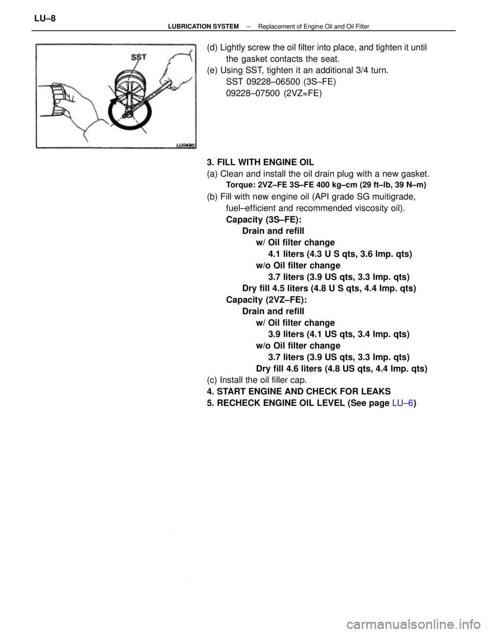
5. RECHECK ENGINE OIL LEVEL (See page LU±6) (d) Lightly screw the oil filter into place, and tighten it until
the gasket contacts the seat.
(e) Using SST, tighten it an additional 3/4 turn.
SST 09228±06500 (3S±FE)
09228±07500 (2VZ=FE)
± LUBRICATION SYSTEMReplacement of Engine Oil and Oil FilterLU±8
Page 1897 of 2389
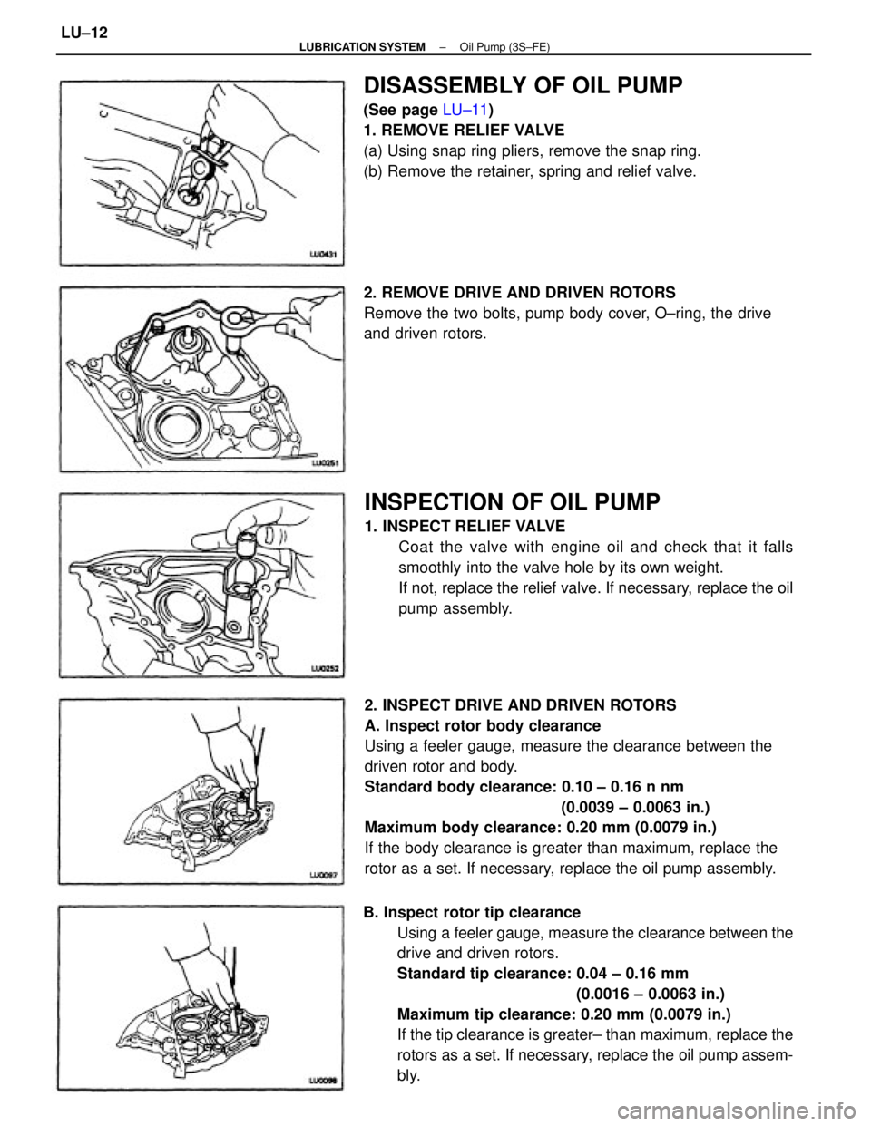
2. INSPECT DRIVE AND DRIVEN ROTORS
A. Inspect rotor body clearance
Using a feeler gauge, measure the clearance between the
driven rotor and body.
Standard body clearance: 0.10 ± 0.16 n nm
(0.0039 ± 0.0063 in.)
Maximum body clearance: 0.20 mm (0.0079 in.)
If the body clearance is greater than maximum, replace the
rotor as a set. If necessary, replace the oil pump assembly.
B. Inspect rotor tip clearance
Using a feeler gauge, measure the clearance between the
drive and driven rotors.
Standard tip clearance: 0.04 ± 0.16 mm
(0.0016 ± 0.0063 in.)
Maximum tip clearance: 0.20 mm (0.0079 in.)
If the tip clearance is greater± than maximum, replace the
rotors as a set. If necessary, replace the oil pump assem-
bly.
INSPECTION OF OIL PUMP
1. INSPECT RELIEF VALVE
Coat the valve with engine oil and check that it falls
smoothly into the valve hole by its own weight.
If not, replace the relief valve. If necessary, replace the oil
pump assembly.
DISASSEMBLY OF OIL PUMP
(See page LU±11)
1. REMOVE RELIEF VALVE
(a) Using snap ring pliers, remove the snap ring.
(b) Remove the retainer, spring and relief valve.
2. REMOVE DRIVE AND DRIVEN ROTORS
Remove the two bolts, pump body cover, O±ring, the drive
and driven rotors.
± LUBRICATION SYSTEMOil Pump (3S±FE)LU±12
Page 1900 of 2389
9. INSTALL FRONT EXHAUST PIPE
(See step 12 on page EM±134)
10. INSTALL ENGINE UNDER COVERS
11. LOWER VEHICLE
12. FILL WITH ENGINE OIL (See page LU±8)
13. START ENGINE AND CHECK FOR LEAKS
14. RECHECK ENGINE OIL LEVEL (See page LU±6)
15. INSTALL HOOD8. INSTALL SUSPENSION LOWER CROSSMEMBER
Torque:
14 mm head bolt
400 kg±cm (32 ft±lb, 43 N±m)
19 mm head bolt
2,120 kg±cm (153 ft±Ib, 208 N±m)
7. INSTALL ENGINE MOUNTING CENTER MEMBER
Torque:
To body 400 kg±cm (29 ft±lb, 39 N±m)
To mounting insulator
490 kg±cm (35 ft±tb, 48 N±m)
(c) Install the oil pan with the seventeen bolts and two
nuts.
Torque: 55 kg±cm (48 in.±Ib. 5.4 N±m)
(d) Install the dipstick.
6. INSTALL STIFFENER PLATE
Torque: 380 kg±cm (27±Ib, 37 N±m)
± LUBRICATION SYSTEMOil Pump (3S±FE)LU±15
Page 1905 of 2389
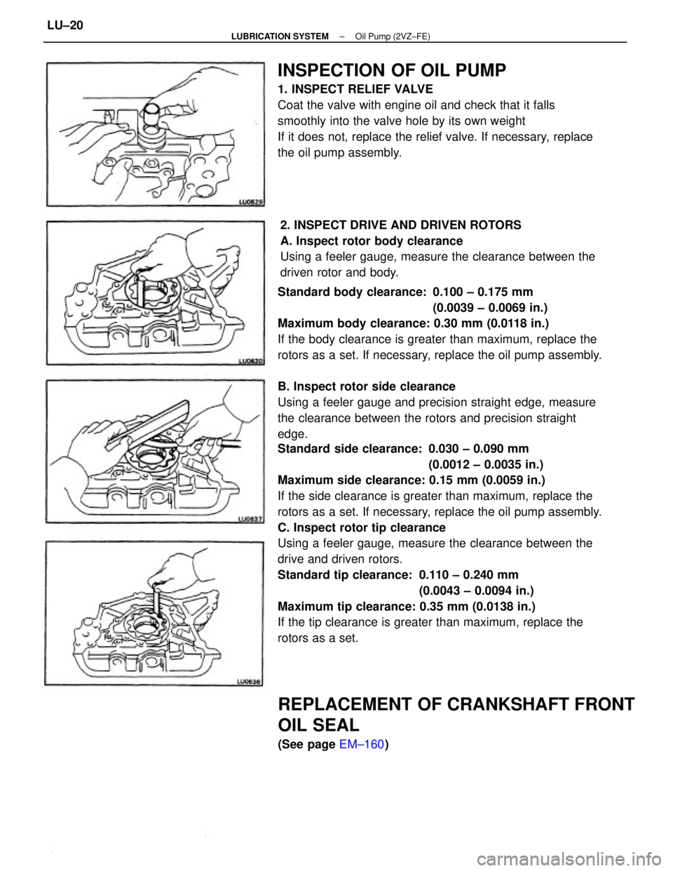
Standard side clearance: 0.030 ± 0.090 mm
(0.0012 ± 0.0035 in.)
Maximum side clearance: 0.15 mm (0.0059 in.)
If the side clearance is greater than maximum, replace the
rotors as a set. If necessary, replace the oil pump assembly.
C. Inspect rotor tip clearance
Using a feeler gauge, measure the clearance between the
drive and driven rotors.
Standard tip clearance: 0.110 ± 0.240 mm
(0.0043 ± 0.0094 in.)
Maximum tip clearance: 0.35 mm (0.0138 in.)
If the tip clearance is greater than maximum, replace the
rotors as a set. Standard body clearance: 0.100 ± 0.175 mm
(0.0039 ± 0.0069 in.)
Maximum body clearance: 0.30 mm (0.0118 in.)
If the body clearance is greater than maximum, replace the
rotors as a set. If necessary, replace the oil pump assembly.
B. Inspect rotor side clearance
Using a feeler gauge and precision straight edge, measure
the clearance between the rotors and precision straight
edge.
INSPECTION OF OIL PUMP
1. INSPECT RELIEF VALVE
Coat the valve with engine oil and check that it falls
smoothly into the valve hole by its own weight
If it does not, replace the relief valve. If necessary, replace
the oil pump assembly.
2. INSPECT DRIVE AND DRIVEN ROTORS
A. Inspect rotor body clearance
Using a feeler gauge, measure the clearance between the
driven rotor and body.
REPLACEMENT OF CRANKSHAFT FRONT
OIL SEAL
(See page EM±160)
± LUBRICATION SYSTEMOil Pump (2VZ±FE)LU±20
Page 1910 of 2389
11. INSTALL FRONT ENGINE MOUNTING BRACKET AND
INSULATOR
(See step 7 on page EM±171)
12. INSTALL ENGINE MOUNTING CENTER MEMBER
(See step 10 on page EM±171)
13. REMOVE FRONT EXHAUST PIPE
(See step 14 on page EM±172)
14. INSTALL SUSPENSION LOWER CROSSMEMBER
(See step 15 on page EM±172)
15. INSTALL ENGINE UNDER COVERS
16. LOWER VEHICLE
17. FILL WITH ENGINE OIL (See page LU±8)
18. START ENGINE AND CHECK FOR LEAKS
19. RECHECK ENGINE OIL LEVEL (See page LU±6)
20. INSTALL HOOD
± LUBRICATION SYSTEMOil Pump (2VZ±FE)LU±25
Page 1912 of 2389
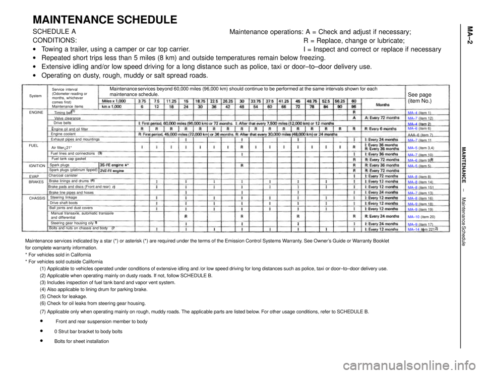
Maintenance services indicated by a star (*) or asterisk (*) are required under the terms of the Emission Control Systems Warranty. See Owner's Guide or Warranty Booklet
for complete warranty information.
* For vehicles sold in California
* For vehicles sold outside California
(1) Applicable to vehicles operated under conditions of extensive idling and /or low speed driving for long distances such as police, taxi or door±to±door delivery use.
(2) Applicable when operating mainly on dusty roads. If not, follow SCHEDULE B.
(3) Includes inspection of fuel tank band and vapor vent system.
(4) Also applicable to lining drum for parking brake.
(5) Check for leakage.
(6) Check for oil leaks from steering gear housing.
(7) Applicable only when operating mainly on rough, muddy roads. The applicable parts are listed below. For other usage conditions, refer to SCHEDULE B.
w
Front and rear suspension member to body
w
0 Strut bar bracket to body bolts
w
Bolts for sheet installation
MAINTENANCE SCHEDULESCHEDULE A
CONDITIONS:
wTowing a trailer, using a camper or car top carrier.
wRepeated short trips less than 5 miles (8 km) and outside temperatures remain below freezing.
wExtensive idling and/or low speed driving for a long distance such as police, taxi or door±to±door delivery use.
wOperating on dusty, rough, muddy or salt spread roads.Maintenance operations: A = Check and adjust if necessary;
R = Replace, change or lubricate;
I = Inspect and correct or replace if necessary
Maintenance services beyond 60,000 miles (96,000 km) should continue to be performed at the same intervals shown for each
maintenance schedule.
Service interval
(Odometer reading or
months, whichever
comes first)
Maintenance items
Manual transaxle, automatic transaxle
and differential Brake pads and discs (Front and rear)
Bolts and nuts on chassis and bodyExhaust pipes and mountings
Steering gear housing oily Brake line pipes and hosesFuel lines and connections
Ball joints and dust coversEngine oil and oil filter
Spark plugs (platinum tipped)MA±4 (item 2)
MA±6 (item 6)
Brake linings and drumsFuel tank cap gasket
Drive shaft boots
MA±14 item 221 MA±10 (item 20) MA±5 (item 3,4)
Steering linkageMA±7 (item 12)
MA±8 (item 14) Valve clearance
MA±8 (item 16)
MA±9 (item 19) MA±7 (item 13) MA±7 (item 11
MA±7 (item 10)
MA±9 (item 18) Charcoal canister
MA±9 (item 17) MA±8 (item 151
See page
(item No.)
Engine coolant
MA±6 (item 9) MA±4 (item 1)
MA±4 (item 2)
MA±5 (item 5)
MA±8 (item 8) AAA±6 (item 7)
Air filter¿21*
Spark plugsTiming belt
Drive belts
IGNITION
CHASSIS BRAKESENGINESystem
EVAP FUEL
± MAINTENANCEMaintenance ScheduleMA±2