Page 2075 of 2389
DISASSEMBLY OF OIL PUMP
1. CHECK OPERATION OF OIL PUMP
Install the oil pump drive gear to the drive rotor, check
that the drive rotor turns smoothly.
2. REMOVE GASKET FROM OIL PUMP CASE
OIL PUMP
± MANUAL TRANSAXLEComponent Parts (Oil Pump)MT±145
Page 2076 of 2389
5. CHECK ROTOR BODY CLEARANCE
(a) Install the oil pump drive gear to the drive rotor.
(b) Using a feeler gauge, measure the body clearance
between the drive rotor and oil pump case.
Standard clearance: 0.10 ± 0.16 mm
(0.0039 ± 0.0063 in.)
Maximum clearance: 0.30 mm (0.0118 in.)
6. CHECK ROTOR TIP CLEARANCE
(a) Install the oil pump drive gear to the drive rotor.
(b) Using a feeler gauge, measure the tip clearance
between the drive and driven rotors.
Standard clearance: 0.08 ± 0.15 mm
(0.0031 ± 0.0059 in.)
Maximum clearance: 0.30 mm (0.0118 in.) 4. REMOVE OIL PUMP COVER
(a) Hold the oil pump cover, remove the two bolts and the
cover.
(b) Remove the spring holder, spring, ball and relief
valve seat. 3. REMOVE BOLT AND OIL STRAINER
± MANUAL TRANSAXLEComponent Parts (Oil Pump)MT±146
Page 2077 of 2389
7. CHECK. SIDE CLEARANCE
Using a precision straight edge and feeler gauge, mea-
sure the side clearance of both rotors.
Standard clearance: 0.03 ± 0.08 mm
(0.0012 ± 0.0031 in.)
Maximum clearance: 0.15 mm (0.0059 in.)
8. REMOVE OIL PUMP DRIVE ROTOR AND DRIVEN
ROTOR
9. IF NECESSARY, REPLACE O±RING
(a) Using a screwdriver, remove the O±ring.
(b) Apply the gear oil to a new O±ring.
(c) Install a new O±ring.
± MANUAL TRANSAXLEComponent Parts (oil Pump)MT±147
Page 2079 of 2389
5. CHECK OPERATION OF OIL PUMP
Insert the oil pump drive gear to the drive rotor, check
that the drive rotor turns smoothly.
6. INSTALL GASKET
Install a new gasket to the oil pump case.
± MANUAL TRANSAXLEComponent Parts (Oil Pump)MT±149
Page 2095 of 2389

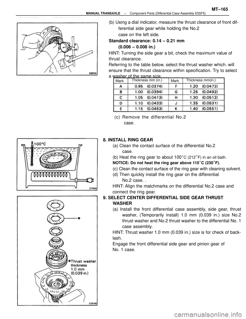
8. INSTALL RING GEAR
(a) Clean the contact surface of the differential No.2
case.
(b) Heat the ring gear to about 100
°C (212°F) in an oil bath.
NOTICE: Do not heat the ring gear above 110°C (230°F).
(c) Clean the contact surface of the ring gear with cleaning solvent.
(d) Then quickly install the ring gear on the differential
No.2 case. .
HINT: Align the matchmarks on the differential No.2 case and
connect the ring gear.
9. SELECT CENTER DIFFERENTIAL SIDE GEAR THRUST
WASHER
(a) Install the front differential case assembly, side gear, thrust
washer, (Temporarily install) 1.0 mm (0.039 in.) size No.2
thrust washer and No.2 thrust washer to the differential No. 1
case assembly.
HINT: Thrust washer 1.0 mm (0.039 in.) size is for check of back-
lash.
Engage the front differential side gear and pinion gear of
No. 1 case. (b) Using a dial indicator, measure the thrust clearance of front dif-
ferential side gear while holding the No.2
case on the left side.
Standard clearance: 0.14 ± 0.21 mm
(0.006 ± 0.008 in.)
HINT: Turning the side gear a bit, check the maximum value of
thrust clearance.
Referring to the table below, select the thrust washer which. will
ensure that the thrust clearance within specification. Try to select
a washer of the same size. . .
(c) Remove the differential No.2
case.
Thickness mm(in.) Thickness mm (in.)
MarkMark
± MANUAL TRANSAXLEComponent Parts (Differential Case Assembly E5SF5)MT±165
Page 2127 of 2389

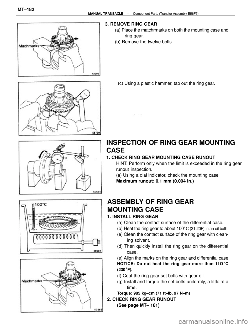
ASSEMBLY OF RING GEAR
MOUNTING CASE
1. INSTALL RING GEAR
(a) Clean the contact surface of the differential case.
(b) Heat the ring gear to about 100
°C (21 20F) in an oil bath.
(e) Clean the contact surface of the ring gear with clean-
ing solvent.
(d) Then quickly install the ring gear on the differential
case.
(e) Align the marks on the ring gear and differential case
NOTICE: Do not heat the ring gear more than 11O°C
(230°F).
(f) Coat the ring gear set bolts with gear oil.
(g) Install and torque the set bolts uniformly, a little at a
time.
Torque: 985 kg±cm (71 ft±Ib, 97 N±m)
2. CHECK RING GEAR RUNOUT
(See page MT± 181)
INSPECTION OF RING GEAR MOUNTING
CASE
1. CHECK RING GEAR MOUNTING CASE RUNOUT
HINT: Perform only when the limit is exceeded in the ring gear
runout inspection.
(a) Using a dial indicator, check the mounting case
Maximum runout: 0.1 mm (0.004 in.) 3. REMOVE RING GEAR
(a) Place the matchrmarks on both the mounting case and
ring gear.
(b) Remove the twelve bolts.
(c) Using a plastic hammer, tap out the ring gear.
± MANUAL TRANSAXLEComponent Parts (Transfer Assembly E56F5)MT±182
Page 2132 of 2389

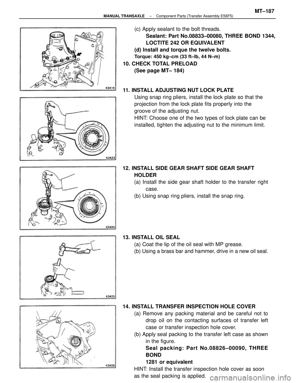
14. INSTALL TRANSFER INSPECTION HOLE COVER
(a) Remove any packing material and be careful not to
drop oil on the contacting surfaces of transfer left
case or transfer inspection hole cover.
(b) Apply seal packing to the transfer left case as shown
in the figure.
Seal packing: Part No.08826±00090, THREE
BOND
1281 or equivalent
HINT: Install the transfer inspection hole cover as soon
as the seal packing is applied.(c) Apply sealant to the bolt threads.
Sealant: Part No.08833±00080, THREE BOND 1344,
LOCTITE 242 OR EQUIVALENT
(d) Install and torque the twelve bolts.
Torque: 450 kg±cm (33 ft±lb, 44 N±m)
10. CHECK TOTAL PRELOAD
(See page MT± 184)
11. INSTALL ADJUSTING NUT LOCK PLATE
Using snap ring pliers, install the lock plate so that the
projection from the lock plate fits properly into the
groove of the adjusting nut.
HINT: Choose one of the two types of lock plate can be
installed, tighten the adjusting nut to the minimum limit.
12. INSTALL SIDE GEAR SHAFT SIDE GEAR SHAFT
HOLDER
(a) Install the side gear shaft holder to the transfer right
case.
(b) Using snap ring pliers, install the snap ring.
13. INSTALL OIL SEAL
(a) Coat the lip of the oil seal with MP grease.
(b) Using a brass bar and hammer, drive in a new oil seal.
± MANUAL TRANSAXLEComponent Parts (Transfer Assembly E56F5)MT±187
Page 2175 of 2389

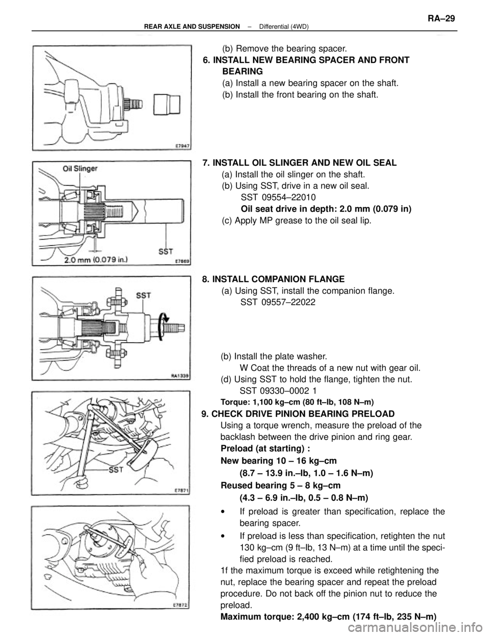
(b) Install the plate washer.
W Coat the threads of a new nut with gear oil.
(d) Using SST to hold the flange, tighten the nut.
SST 09330±0002 1
Torque: 1,100 kg±cm (80 ft±Ib, 108 N±m)
9. CHECK DRIVE PINION BEARING PRELOAD
Using a torque wrench, measure the preload of the
backlash between the drive pinion and ring gear.
Preload (at starting) :
New bearing 10 ± 16 kg±cm
(8.7 ± 13.9 in.±Ib, 1.0 ± 1.6 N±m)
Reused bearing 5 ± 8 kg±cm
(4.3 ± 6.9 in.±Ib, 0.5 ± 0.8 N±m)
wIf preload is greater than specification, replace the
bearing spacer.
wIf preload is less than specification, retighten the nut
130 kg±cm (9 ft±Ib, 13 N±m) at a time until the speci-
fied preload is reached.
1f the maximum torque is exceed while retightening the
nut, replace the bearing spacer and repeat the preload
procedure. Do not back off the pinion nut to reduce the
preload.
Maximum torque: 2,400 kg±cm (174 ft±lb, 235 N±m)(b) Remove the bearing spacer.
6. INSTALL NEW BEARING SPACER AND FRONT
BEARING
(a) Install a new bearing spacer on the shaft.
(b) Install the front bearing on the shaft.
7. INSTALL OIL SLINGER AND NEW OIL SEAL
(a) Install the oil slinger on the shaft.
(b) Using SST, drive in a new oil seal.
SST 09554±22010
Oil seat drive in depth: 2.0 mm (0.079 in)
(c) Apply MP grease to the oil seal lip.
8. INSTALL COMPANION FLANGE
(a) Using SST, install the companion flange.
SST 09557±22022
± REAR AXLE AND SUSPENSIONDifferential (4WD)RA±29