Page 2176 of 2389
11. CONNECT PROPELLER SHAFT
(a) Align the matchmarks on the flanges and connect the
propeller shaft with the four bolts, washers and nuts.
(b) Torque the bolts and nuts.
Torque: 760 kg±cm (54 ft±Ib, 74 N±m)
13. CHECK OIL LEVEL
Oil grade: AN GL±5 hypoid gear oil
Viscosity: Above ± 18
°C (0°F) SAE 90
Below ± 18°C (0°F) SAE 80 W ± 90
Capacity: 1.1 liters (1.2 US qts, 1.0 Imp.qts)
12. INSTALL REAR CROSSMEMBER
Torque: 730 kg±cm (53 ft±Ib, 72 N±m)
10. STAKE DRIVE PINION NUT
± REAR AXLE AND SUSPENSIONDifferential (4WD)RA±30
Page 2186 of 2389

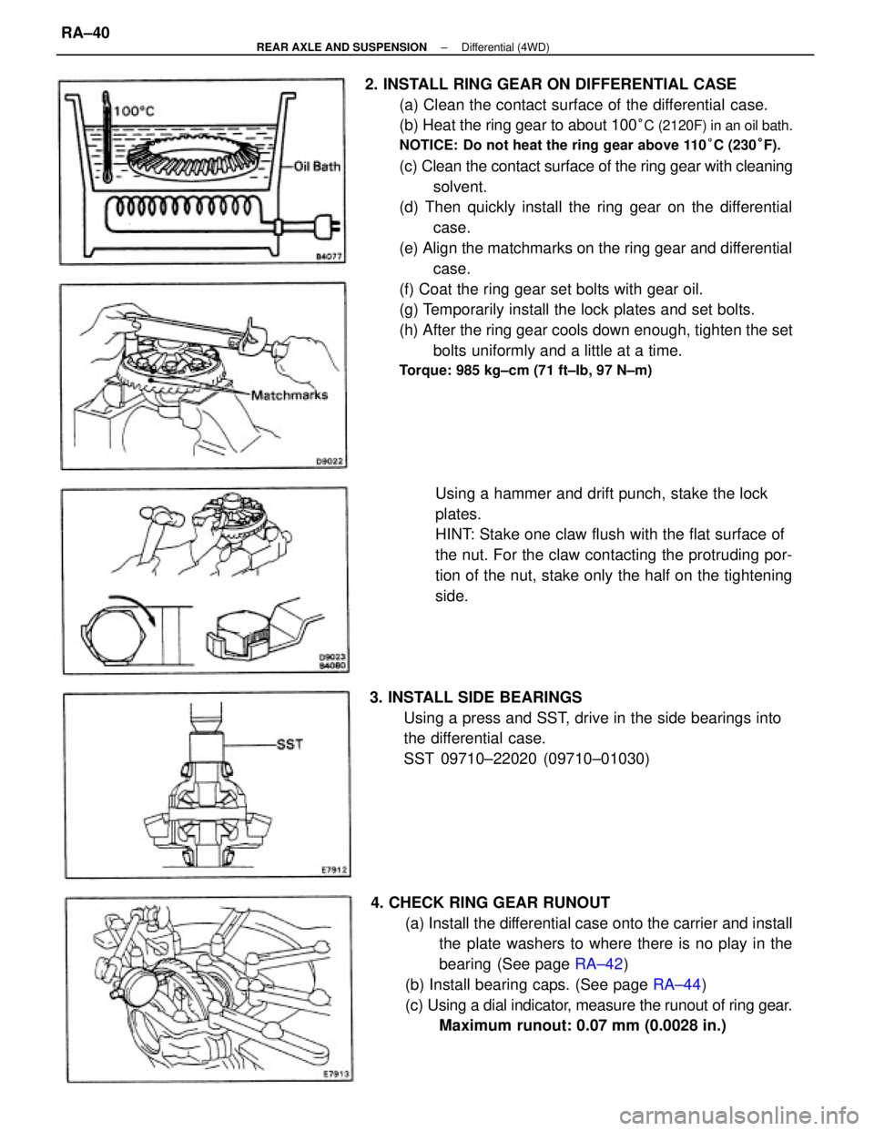
2. INSTALL RING GEAR ON DIFFERENTIAL CASE
(a) Clean the contact surface of the differential case.
(b) Heat the ring gear to about 100
°C (2120F) in an oil bath.
NOTICE: Do not heat the ring gear above 110°C (230°F).
(c) Clean the contact surface of the ring gear with cleaning
solvent.
(d) Then quickly install the ring gear on the differential
case.
(e) Align the matchmarks on the ring gear and differential
case.
(f) Coat the ring gear set bolts with gear oil.
(g) Temporarily install the lock plates and set bolts.
(h) After the ring gear cools down enough, tighten the set
bolts uniformly and a little at a time.
Torque: 985 kg±cm (71 ft±Ib, 97 N±m)
4. CHECK RING GEAR RUNOUT
(a) Install the differential case onto the carrier and install
the plate washers to where there is no play in the
bearing (See page RA±42)
(b) Install bearing caps. (See page RA±44)
(c) Using a dial indicator, measure the runout of ring gear.
Maximum runout: 0.07 mm (0.0028 in.) Using a hammer and drift punch, stake the lock
plates.
HINT: Stake one claw flush with the flat surface of
the nut. For the claw contacting the protruding por-
tion of the nut, stake only the half on the tightening
side.
3. INSTALL SIDE BEARINGS
Using a press and SST, drive in the side bearings into
the differential case.
SST 09710±22020 (09710±01030)
± REAR AXLE AND SUSPENSIONDifferential (4WD)RA±40
Page 2198 of 2389

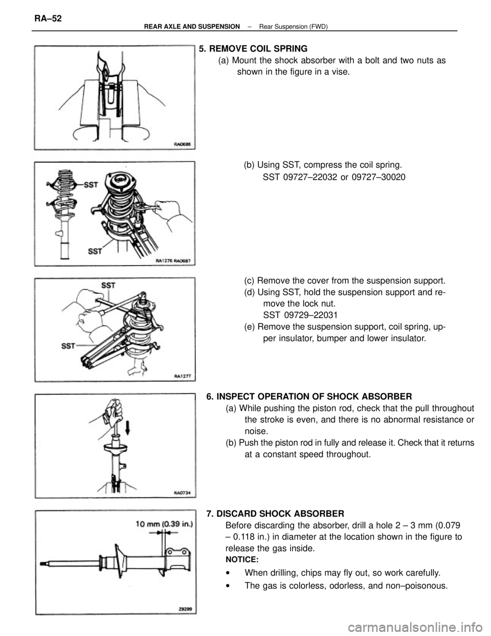
7. DISCARD SHOCK ABSORBER
Before discarding the absorber, drill a hole 2 ± 3 mm (0.079
± 0.118 in.) in diameter at the location shown in the figure to
release the gas inside.
NOTICE:
wWhen drilling, chips may fly out, so work carefully.
wThe gas is colorless, odorless, and non±poisonous. 6. INSPECT OPERATION OF SHOCK ABSORBER
(a) While pushing the piston rod, check that the pull throughout
the stroke is even, and there is no abnormal resistance or
noise.
(b) Push the piston rod in fully and release it. Check that it returns
at a constant speed throughout. (c) Remove the cover from the suspension support.
(d) Using SST, hold the suspension support and re-
move the lock nut.
SST 09729±22031
(e) Remove the suspension support, coil spring, up-
per insulator, bumper and lower insulator. 5. REMOVE COIL SPRING
(a) Mount the shock absorber with a bolt and two nuts as
shown in the figure in a vise.
(b) Using SST, compress the coil spring.
SST 09727±22032 or 09727±30020
± REAR AXLE AND SUSPENSIONRear Suspension (FWD)RA±52
Page 2260 of 2389

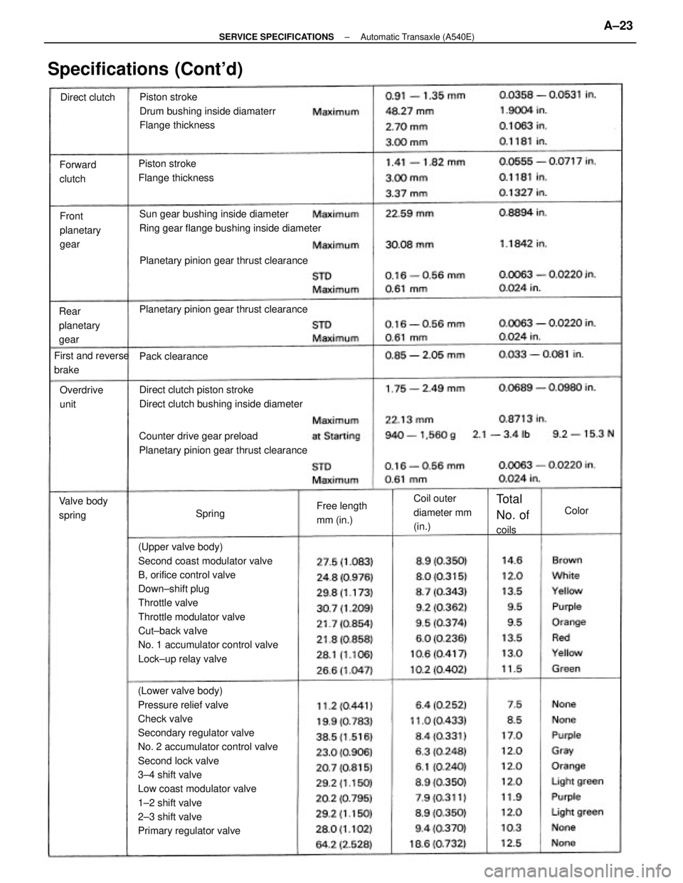
(Lower valve body)
Pressure relief valve
Check valve
Secondary regulator valve
No. 2 accumulator control valve
Second lock valve
3±4 shift valve
Low coast modulator valve
1±2 shift valve
2±3 shift valve
Primary regulator valve(Upper valve body)
Second coast modulator valve
B, orifice control valve
Down±shift plug
Throttle valve
Throttle modulator valve
Cut±back vaIve
No. 1 accumulator control valve
Lock±up relay valvePiston stroke
Drum bushing inside diamaterr
Flange thickness
Sun gear bushing inside diameter
Ring gear flange bushing inside diameter
Counter drive gear preload
Planetary pinion gear thrust clearanceDirect clutch piston stroke
Direct clutch bushing inside diameter Planetary pinion gear thrust clearancePlanetary pinion gear thrust clearance
Specifications (Cont'd)
Piston stroke
Flange thickness
Coil outer
diameter mm
(in.) Rear
planetary
gearFront
planetary
gear Forward
clutch
First and reverse
brake
Free length
mm (in.) Valve body
springOverdrive
unit
Total
No. of
coils Pack clearance Direct clutch
SpringColor
± SERVICE SPECIFICATIONSAutomatic Transaxle (A540E)A±23
Page 2299 of 2389
SST (SPECIAL SERVICE TOOLS) (Cont'd)
Remarks:
* 1 2VZ±FE only
* 2 E52 and E56F5
* 3 E56F5 only
* 4 Speedometer driven gear oil seal
* 5 FWD/VZV21 and 4WD Windshield Moulding
Remover
Altemator Pulley Set
Nut Wrench Set
Diagnosis Check
WiringAlternator Rear
Bearing PullerDoor Hinge Set
Bolt Wrench
Wiring º'Aº EFI
Inspection
Hexagon 8 mm
WrenchOil Pressure
Switch Socket
Back±up Light
Switch Tool
Wiring ªFº
EFI Inspection
Spring Tension Tool
IllustrationPart Name Section
Part No.
Puller Set
EM
RA
BO
± SST AND SSMSST (Special Service Tools)C±19
Page 2300 of 2389
SST (SPECIAL SERVICE TOOLS) (Cont'd)
NOTE: For reference to SSTs for the Air Conditioning System see page AC±15.
Remarks:
* 1 E52 and E56F5
* 2 Drive shaft dust cover
* 3 4WD only A.B.S. Actuator
Checker and
Sub±harness
A.B.S. Actuator
Checker Sheet ºAºBearing Remover
Attachment
Oil Pressure
Gauge SetBearing Remover
IllustrationPart Name
Universal Puller
Part No.Section
± SST AND SSMSST (Special Service Tools)C±20
Page 2314 of 2389
INSPECTION AND REPAIR OF STARTER
Armature Coil
1. INSPECT COMMUTATOR FOR OPEN CIRCUIT
Using an ohmmeter, check that there is continuity between the
segments of the commutator
If there is no continuity, replace the armature.
2. INSPECT COMMUTATOR FOR RUNOUT
(a) Place the communicator on V±blocks.
(b) Using a dial indicator, measure the circle runout.
Maximum circle runout: 0.05 mm (0.0020 in.)
If the circle runout is greater than maximum, correct it with
on a lathe.
Commutator
1. INSPECT COMMUTATOR FOR DIRTY AND BURNT
SURFACE
If the surface is dirty or burnt, correct with sandpaper
(No.400) or on a lathe.2. INSPECT COMMUTATOR FOR GROUND
Using an ohmmeter, check that there is no continuity between
the commutator and armature coil core.
If there is continuity, replace the armature.
3. INSPECT COMMUTATOR DIAMETER
Using calipers, measure the diameter.
Standard diameter: 30.0 mm (1.181 in.)
Minimum diameter 29.0 mm (1.142 in.)
± STARTING SYSTEMStarterST±6
Page 2315 of 2389

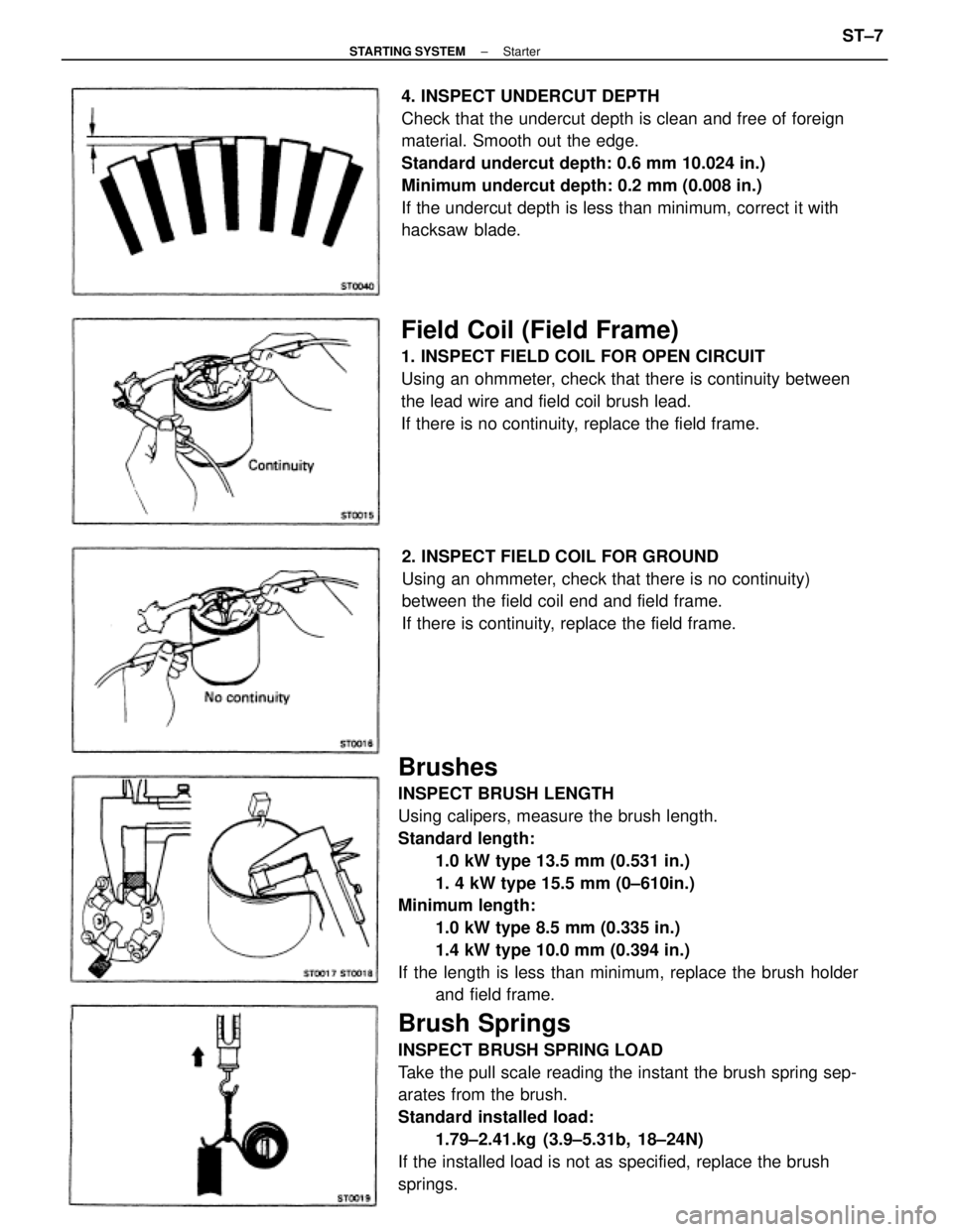
Brushes
INSPECT BRUSH LENGTH
Using calipers, measure the brush length.
Standard length:
1.0 kW type 13.5 mm (0.531 in.)
1. 4 kW type 15.5 mm (0±610in.)
Minimum length:
1.0 kW type 8.5 mm (0.335 in.)
1.4 kW type 10.0 mm (0.394 in.)
If the length is less than minimum, replace the brush holder
and field frame.
Brush Springs
INSPECT BRUSH SPRING LOAD
Take the pull scale reading the instant the brush spring sep-
arates from the brush.
Standard installed load:
1.79±2.41.kg (3.9±5.31b, 18±24N)
If the installed load is not as specified, replace the brush
springs.4. INSPECT UNDERCUT DEPTH
Check that the undercut depth is clean and free of foreign
material. Smooth out the edge.
Standard undercut depth: 0.6 mm 10.024 in.)
Minimum undercut depth: 0.2 mm (0.008 in.)
If the undercut depth is less than minimum, correct it with
hacksaw blade.
Field Coil (Field Frame)
1. INSPECT FIELD COIL FOR OPEN CIRCUIT
Using an ohmmeter, check that there is continuity between
the lead wire and field coil brush lead.
If there is no continuity, replace the field frame.
2. INSPECT FIELD COIL FOR GROUND
Using an ohmmeter, check that there is no continuity)
between the field coil end and field frame.
If there is continuity, replace the field frame.
± STARTING SYSTEMStarterST±7