Page 1924 of 2389

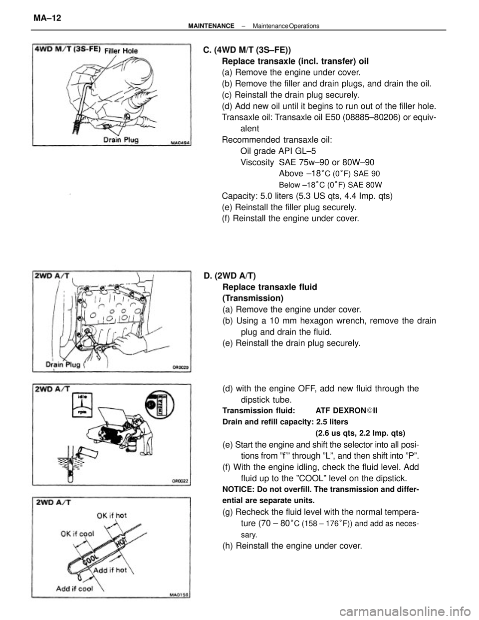
C. (4WD M/T (3S±FE))
Replace transaxle (incl. transfer) oil
(a) Remove the engine under cover.
(b) Remove the filler and drain plugs, and drain the oil.
(c) Reinstall the drain plug securely.
(d) Add new oil until it begins to run out of the filler hole.
Transaxle oil: Transaxle oil E50 (08885±80206) or equiv-
alent
Recommended transaxle oil:
Oil grade API GL±5
Viscosity SAE 75w±90 or 80W±90
Above ±18
°C (0°F) SAE 90
Below ±18°C (0°F) SAE 80W
Capacity: 5.0 liters (5.3 US qts, 4.4 Imp. qts)
(e) Reinstall the filler plug securely.
(f) Reinstall the engine under cover.
(d) with the engine OFF, add new fluid through the
dipstick tube.
Transmission fluid: ATF DEXRON�II
Drain and refill capacity: 2.5 liters
(2.6 us qts, 2.2 Imp. qts)
(e) Start the engine and shift the selector into all posi-
tions from ºf'º through ºLº, and then shift into ºPº.
(f) With the engine idling, check the fluid level. Add
fluid up to the ºCOOLº level on the dipstick.
NOTICE: Do not overfill. The transmission and differ-
ential are separate units.
(g) Recheck the fluid level with the normal tempera-
ture (70 ± 80
°C (158 ± 176°F)) and add as neces-
sary.
(h) Reinstall the engine under cover. D. (2WD A/T)
Replace transaxle fluid
(Transmission)
(a) Remove the engine under cover.
(b) Using a 10 mm hexagon wrench, remove the drain
plug and drain the fluid.
(e) Reinstall the drain plug securely.
± MAINTENANCEMaintenance OperationsMA±12
Page 1926 of 2389

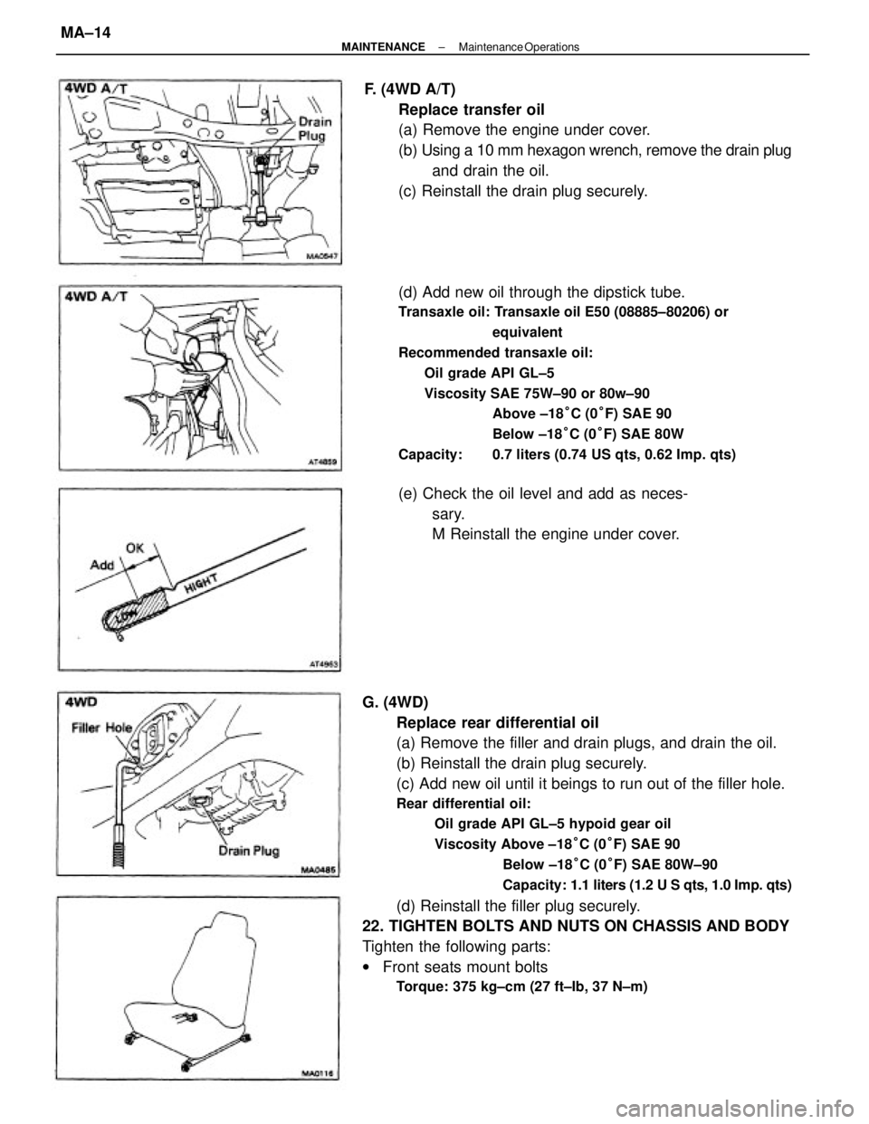
G. (4WD)
Replace rear differential oil
(a) Remove the filler and drain plugs, and drain the oil.
(b) Reinstall the drain plug securely.
(c) Add new oil until it beings to run out of the filler hole.
Rear differential oil:
Oil grade API GL±5 hypoid gear oil
Viscosity Above ±18°C (0°F) SAE 90
Below ±18°C (0°F) SAE 80W±90
Capacity: 1.1 liters (1.2 U S qts, 1.0 Imp. qts)
(d) Reinstall the filler plug securely.
22. TIGHTEN BOLTS AND NUTS ON CHASSIS AND BODY
Tighten the following parts:
wFront seats mount bolts
Torque: 375 kg±cm (27 ft±Ib, 37 N±m)
(d) Add new oil through the dipstick tube.
Transaxle oil: Transaxle oil E50 (08885±80206) or
equivalent
Recommended transaxle oil:
Oil grade API GL±5
Viscosity SAE 75W±90 or 80w±90
Above ±18°C (0°F) SAE 90
Below ±18°C (0°F) SAE 80W
Capacity: 0.7 liters (0.74 US qts, 0.62 Imp. qts)
F. (4WD A/T)
Replace transfer oil
(a) Remove the engine under cover.
(b) Using a 10 mm hexagon wrench, remove the drain plug
and drain the oil.
(c) Reinstall the drain plug securely.
(e) Check the oil level and add as neces-
sary.
M Reinstall the engine under cover.
± MAINTENANCEMaintenance OperationsMA±14
Page 1946 of 2389

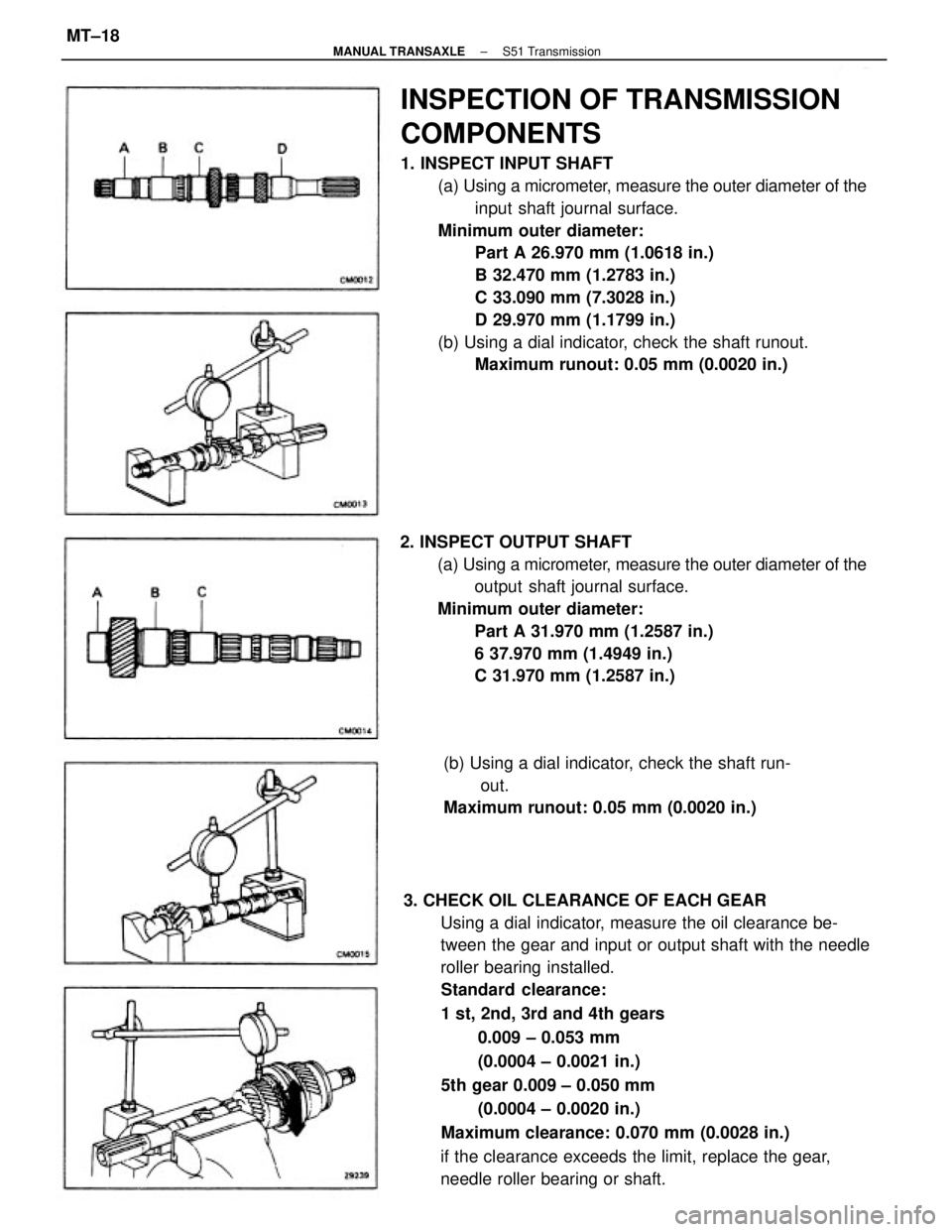
3. CHECK OIL CLEARANCE OF EACH GEAR
Using a dial indicator, measure the oil clearance be-
tween the gear and input or output shaft with the needle
roller bearing installed.
Standard clearance:
1 st, 2nd, 3rd and 4th gears
0.009 ± 0.053 mm
(0.0004 ± 0.0021 in.)
5th gear 0.009 ± 0.050 mm
(0.0004 ± 0.0020 in.)
Maximum clearance: 0.070 mm (0.0028 in.)
if the clearance exceeds the limit, replace the gear,
needle roller bearing or shaft.
INSPECTION OF TRANSMISSION
COMPONENTS
1. INSPECT INPUT SHAFT
(a) Using a micrometer, measure the outer diameter of the
input shaft journal surface.
Minimum outer diameter:
Part A 26.970 mm (1.0618 in.)
B 32.470 mm (1.2783 in.)
C 33.090 mm (7.3028 in.)
D 29.970 mm (1.1799 in.)
(b) Using a dial indicator, check the shaft runout.
Maximum runout: 0.05 mm (0.0020 in.)
2. INSPECT OUTPUT SHAFT
(a) Using a micrometer, measure the outer diameter of the
output shaft journal surface.
Minimum outer diameter:
Part A 31.970 mm (1.2587 in.)
6 37.970 mm (1.4949 in.)
C 31.970 mm (1.2587 in.)
(b) Using a dial indicator, check the shaft run-
out.
Maximum runout: 0.05 mm (0.0020 in.)
± MANUAL TRANSAXLES51 TransmissionMT±18
Page 1947 of 2389
5. MEASURE CLEARANCE OF SHIFT FORKS AND HUB
SLEEVES
Using a feeler gauge, measure the clearance between the
hub sleeve and shift fork.
Maximum clearance: 1.0 mm (0.039 in.)
If the clearance exceeds the limit, replace the shift fork or
hub sleeve.
(e) Using SST, press in a new bearing.
SST 09310±35010 .
(d) Install the transaxle case oil receiver and torque
the bolt.
Torque: 75 kg±cm (65 in.±Ib, 7.4 11f±m)
6. IF NECESSARY, REPLACE INPUT SHAFT FRONT
BEARING
(a) Remove the bolt and transaxle case oil receiver.
(b) Using SST, pull out the bearing.
SST 09308±00010 (b) Measure the clearance between the synchronizer ring
back and the gear spline end.
Minimum clearance: 0.6 mm 10.024 in.)
If the clearance is less than the limit, replace the synchro-
nizer ring. 4. INSPECT SYNCHRONIZER RINGS
(a) Turn the ring and push it in to check the braking action.
± MANUAL TRANSAXLES51 TransmissionMT±19
Page 1977 of 2389
2. CHECK OIL CLEARANCE OF THIRD AND FOURTH
GEAR
Using dial indicator, measure the oil clearance between
the gear and shaft.
Standard clearance:
3rd gear 0.009 ± 0.053 mm
(0.0004 ± 0.0021 in.)
4th gear 0.009 ± 0.051 mm
(0.0004 ± 0.0020 in.)
Maximum clearance:
3rd and 4th gear 0.070 mm (0.0028 in.)
If clearance exceeds the limit, replace the gear, needle
roller bearing or shaft.
3. REMOVE SNAP RING
Using two screwdrivers and a hammer, tap out the snap
ring.
4. REMOVE RADIAL BALL BEARING AND FOURTH GEAR
Using SST and a press, remove the radial ball bearing.
SST 09950±00020
5.REMOVE NEEDLE ROLLER BEARINGS, SPACER AND
SYNCHRONIZER RING
7. REMOVE NO.2 CLUTCH HUB ASSEMBLY,
SYNCHRONIZER RING AND THIRD GEAR
Using a press, remove No.2 hub sleeve, 3rd gear, syn-
chronizer ring and needle roller bearings.
8. REMOVE NEEDLE ROLLER BEARING6. REMOVE SNAP RING
Using two screwdrivers and a hammer, tap out the snap ring.
± MANUAL TRANSAXLEComponent PartsMT±63
Page 1993 of 2389
2. MEASURE CLEARANCE OF SHIFT FORKS AND HUB
SLEEVE
Using a feeler gauge, measure the clearance between
the hub sleeve and shift fork.
Maximum clearance: 1.0 mm (0.039 in.)
If the clearance exceeds the limit, replace the shift fork
or hub sleeve.
INSPECTION OF COMPONENT PARTS
1. INSPECT SYNCHRONIZER RING FOR FIFTH GEAR
(a) Check for wear or damage.
(b) Turn the ring and push it in to check the braking action.
(e) Measure the clearance between the synchronizer
ring back and the gear spline end.
Minimum clearance: 0.6 mm (0.024 in.)
If the clearance is less than the limit, replace the
synchronizer ring.
4. IF NECESSARY, REPLACE INPUT SHAFT BEARING
AND OIL SEAL
(a) Using SST, pull out the bearing.
SST 09812±65014 3. REMOVE TRANSAXLE CASE RECEIVER
± MANUAL TRANSAXLERemoval of Component PartsMT±58
Page 1998 of 2389
2.CHECK± OIL CLEARANCE OF FIRST AND SECOND
GEAR
Using dial indicator, measure the oil clearance between
the gear and shaft. .
Standard clearance: .
1st gear 0.009 ± 0.051 mm .
(0.0004 ± 0.0020 in.)
2nd gear 0.009 ± 0.053 mm(0.0004 ± 0.0021 in.)
Maximum clearance:
1 st and 2nd gear 0.070 mm'(0.0028 in.)
If the clearance exceeds the limit, replace the gear,
needle roller bearing or shaft.
3. REMOVE OUTPUT SHAFT REAR± BEARING, FOURTH
DRIVEN GEAR AND SPACER
(a) Using a press, remove the bearing and 4th driven gear.
(b) Remove the spacer.
7. REMOVE NO.1 HUB SLEEVE ASSEMBLY AND FIRST
GEAR
Using a press, remove No. 1 hub sleeve and 1 st gear.
8. REMOVE SYNCHRONIZER RING AND NEEDLE
ROLLER' BEARING 4. REMOVE THIRD DRIVEN GEAR AND SECOND GEAR
Using a press, remove the 3rd driven gear and 2nd
gear.
5. REMOVE NEEDLE ROLLER BEARINGS, SPACER AND
SYNCHRONIZER RING
6. REMOVE SNAP RING
Using snap ring pliers, remove the snap ring.
± MANUAL TRANSAXLEComponent PartsMT±69
Page 2003 of 2389
DISASSEMBLY OF OIL PUMP
1. CHECK OPERATION OF OIL PUMP
Install the oil pump drive gear to the drive rotor, check
that the drive rotor turn smoothly.
Oil Pump Assembly
2. REMOVE GASKET TO OIL PUMP CASE
± MANUAL TRANSAXLEComponent PartsMT±74