Page 1397 of 2389
9. INSTALL BEARING LOCK NUT, LOCK NUT CAP AND
NEW COTTER PIN
(a) Torque the bearing lock nut while depressing the brake
pedal.
Torque: 1,900 kg±cm (137 ft±Ib, 186 N±m)
(b) Install the lock nut cap and, using pliers, install a new
cotter pin. 8. TIGHTEN SIX HEXAGON BOLTS
Using SST, tighten the six hexagon bolts while depress-
ing the brake pedal.
SST 09043±88010
Torque: 660 kg±cm (48 ft±Ib, 65 N±m)
10. FILL TRANSAXLE WITH GEAR OIL
(See page MT±45)
11. INSTALL ENGINE UNDER COVERS
12. CHECK FRONT WHEEL ALIGNMENT7. CONNECT STEERING KNUCKLE TO LOWER ARM
Torque: 1,150 kg±cm (83 ft±Ib, 113 N±m)
± FRONT AXLE AND SUSPENSIONFront Drive Shaft (FWD VZV21 )FA±40
Page 1406 of 2389

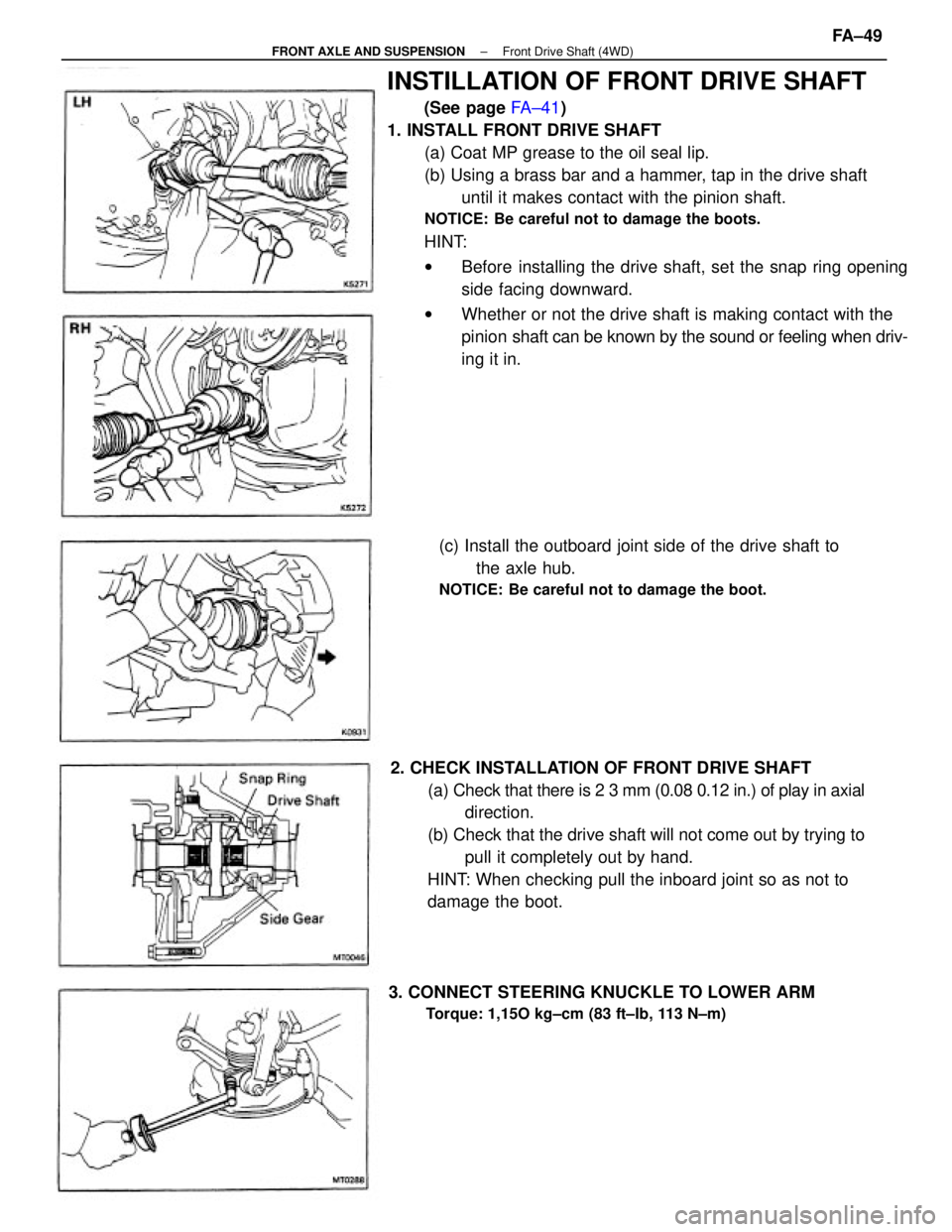
INSTILLATION OF FRONT DRIVE SHAFT
(See page FA±41)
1. INSTALL FRONT DRIVE SHAFT
(a) Coat MP grease to the oil seal lip.
(b) Using a brass bar and a hammer, tap in the drive shaft
until it makes contact with the pinion shaft.
NOTICE: Be careful not to damage the boots.
HINT:
wBefore installing the drive shaft, set the snap ring opening
side facing downward.
wWhether or not the drive shaft is making contact with the
pinion shaft can be known by the sound or feeling when driv-
ing it in.
2. CHECK INSTALLATION OF FRONT DRIVE SHAFT
(a) Check that there is 2 3 mm (0.08 0.12 in.) of play in axial
direction.
(b) Check that the drive shaft will not come out by trying to
pull it completely out by hand.
HINT: When checking pull the inboard joint so as not to
damage the boot.(c) Install the outboard joint side of the drive shaft to
the axle hub.
NOTICE: Be careful not to damage the boot.
3. CONNECT STEERING KNUCKLE TO LOWER ARM
Torque: 1,15O kg±cm (83 ft±Ib, 113 N±m)
± FRONT AXLE AND SUSPENSIONFront Drive Shaft (4WD)FA±49
Page 1407 of 2389
6. FILL TRANSAXLE WITH GEAR OIL OR FLUID
M/T (See page MT±1 17)
A/T Fluid type: ATF DEXRON) II
7. INSTALL ENGINE UNDER COVERS
8. INSTALL WHEELS
9. CHECK FRONT WHEEL ALIGNMENT
(See page FA ± 3) 5. INSTALL BEARING LOCK NUT, LOCK NUT CAP AND
COTTER PIN
(a) Torque the bearing lock nut while depressing the brake
pedal.
Torque: 1, 900 kg±cm (137 ft±Ib, 186 N±m )
(b) Install the lock nut cap and, using pliers, install a new
cotter pin. 4. CONNECT TIE ROD END TO STEERING KNUCKLE
Install and torque the nut, and secure it with a new cotter pin.
Torque: 500 kg±cm (36 ft±Ib, 49 N±m)
± FRONT AXLE AND SUSPENSIONFront Drive Shaft (4WD)FA±50
Page 1410 of 2389
INSPECTION OF FRONT SHOCK
ABSORBER
INSPECT FRONT SHOCK ABSORBER
(a) While pushing the piston rod, check that the pull
through out the stroke is even, and there is no abnormal
resistance or noise.
(b) Push the piston rod in fully and release it. Check that it re-
turns at a con¿¿ant speed through out.
If the shock absorber operation is defective, replace the
shock absorber as an assembly.
NOTICE: Before discarding the shock absorber, first loosen the
ring nut 2 or 3 turns with SST to release the gas completery.
SST 09720±00012 (09721±00071)
(b) Using SST, hold the spring seat so that it will not
turn, and remove the nut.
SST 09727±22032 or 09727±30020,09729±22031
(c) Remove the suspension support, spring seat,
spring, insulators and bumper. 5. REMOVE COIL SPRING
(a) Using SST, compress the coil spring.
SST 09727±22032 or 09727±30020
± FRONT AXLE AND SUSPENSIONFront Shock AbsorberFA±53
Page 1413 of 2389
Ball Joints
INSPECTION OF BALL JOINTS
1. INSPECT BALL JOINTS FOR EXCESSIVE LOOSENESS
(a) Jack up the front of the vehicle and place a wooden
block with the height of 180 ± 200 mm (7.09 ± 7.87
in.) under one front tire.
(b) Lower the jack until there is about half a load on one
front of coil spring. Place stands under the vehicle
for safety.
(e) Make sure the front wheels are in a straight forward
position and block the wheel with chocks.
(d) Move the lower arm up and down and check that the
ball joint has no excessive play.
Ball joint vertical play: 0 mm (0 in.)
FRONT SUSPENSION
COMPONENTS
± FRONT AXLE AND SUSPENSIONFront SuspensionFA±56
Page 1835 of 2389
4. As some tachometers are not compatible with this igni-
tion system, we recommend that you confirm the
compatibility of your unit before use.
5. NEVER allow the tachometer test probe to touch ground
as this could damage the igniter and/or ignition coil.
6. Do not disconnect the battery when the engine is run-
ning.
7. Check that the igniter is properly grounded to the body.
PRECAUTIONS
1. Do not leave the ignition switch on for more than 10
minutes if the engine will not start.
2. (3S±FE)
When a tachometer is connected to the system, con-
nect the test probe of the tachometer to service con-
nector of the distributor.
3. (2VZ±FE)
When a tachometer is connected to the system, con-
nect the test probe of the tachometer to terminal IG E)
of the check connector.
± IGNITION SYSTEMPrecautionsIG±2
Page 1838 of 2389

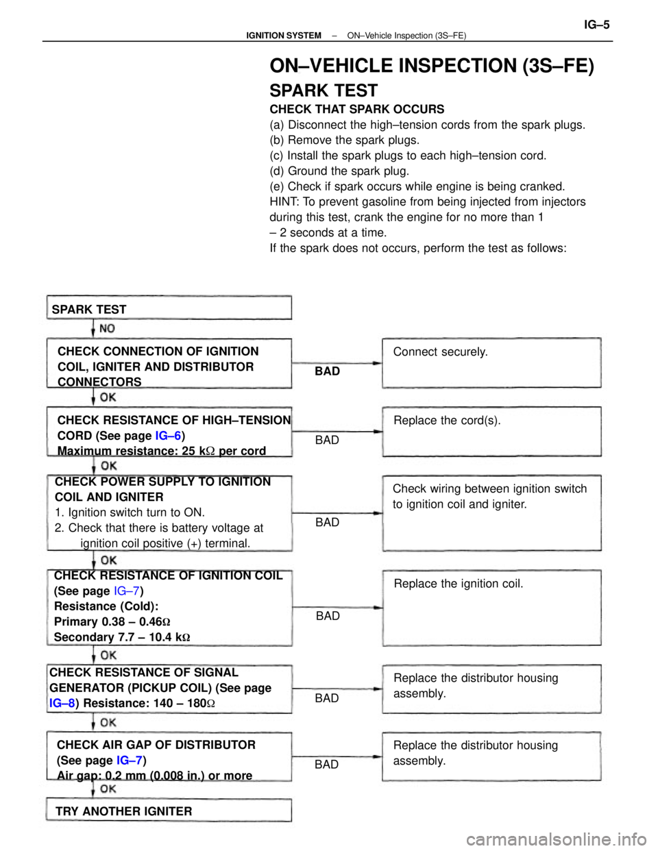
ON±VEHICLE INSPECTION (3S±FE)
SPARK TEST
CHECK THAT SPARK OCCURS
(a) Disconnect the high±tension cords from the spark plugs.
(b) Remove the spark plugs.
(c) Install the spark plugs to each high±tension cord.
(d) Ground the spark plug.
(e) Check if spark occurs while engine is being cranked.
HINT: To prevent gasoline from being injected from injectors
during this test, crank the engine for no more than 1
± 2 seconds at a time.
If the spark does not occurs, perform the test as follows:
CHECK RESISTANCE OF IGNITION COIL
(See page IG±7)
Resistance (Cold):
Primary 0.38 ± 0.46
�
Secondary 7.7 ± 10.4 k�
CHECK POWER SUPPLY TO IGNITION
COIL AND IGNITER
1. Ignition switch turn to ON.
2. Check that there is battery voltage at
ignition coil positive (+) terminal. CHECK RESISTANCE OF HIGH±TENSION
CORD (See page IG±6)
Maximum resistance: 25 k� per cord
CHECK RESISTANCE OF SIGNAL
GENERATOR (PICKUP COIL) (See page
IG±8) Resistance: 140 ± 180
�
CHECK AIR GAP OF DISTRIBUTOR
(See page IG±7)
Air gap: 0.2 mm (0.008 in.) or moreCHECK CONNECTION OF IGNITION
COIL, IGNITER AND DISTRIBUTOR
CONNECTORS
Check wiring between ignition switch
to ignition coil and igniter.
Replace the distributor housing
assembly.
Replace the distributor housing
assembly.Replace the ignition coil.
TRY ANOTHER IGNITERReplace the cord(s). Connect securely. SPARK TEST
BAD BAD
BAD
BAD BAD
BAD
± IGNITION SYSTEMON±Vehicle Inspection (3S±FE)IG±5
Page 1842 of 2389

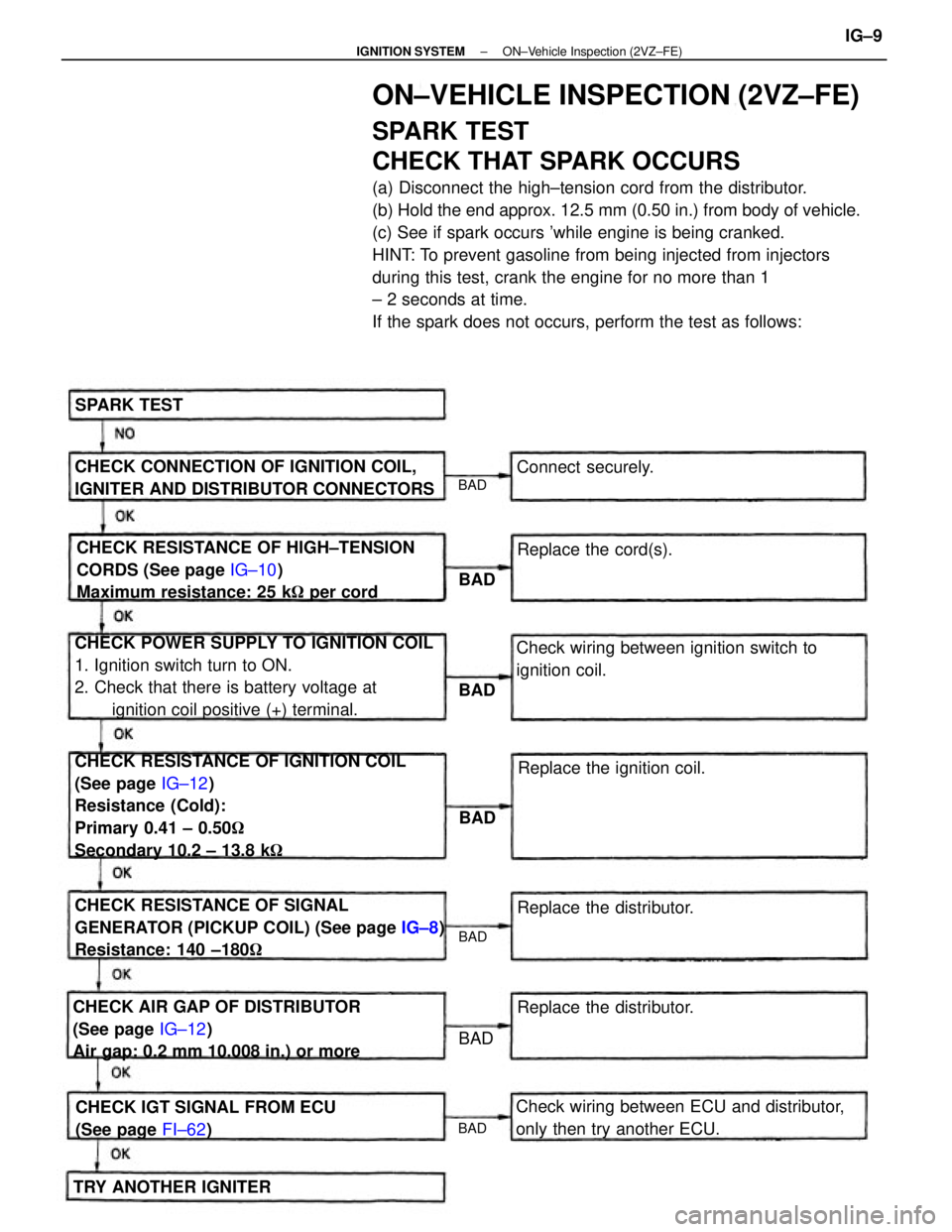
ON±VEHICLE INSPECTION (2VZ±FE)
SPARK TEST
CHECK THAT SPARK OCCURS
(a) Disconnect the high±tension cord from the distributor.
(b) Hold the end approx. 12.5 mm (0.50 in.) from body of vehicle.
(c) See if spark occurs 'while engine is being cranked.
HINT: To prevent gasoline from being injected from injectors
during this test, crank the engine for no more than 1
± 2 seconds at time.
If the spark does not occurs, perform the test as follows:
CHECK RESISTANCE OF IGNITION COIL
(See page IG±12)
Resistance (Cold):
Primary 0.41 ± 0.50�
Secondary 10.2 ± 13.8 k� CHECK POWER SUPPLY TO IGNITION COIL
1. Ignition switch turn to ON.
2. Check that there is battery voltage at
ignition coil positive (+) terminal.
CHECK RESISTANCE OF SIGNAL
GENERATOR (PICKUP COIL) (See page IG±8)
Resistance: 140 ±180� CHECK RESISTANCE OF HIGH±TENSION
CORDS (See page IG±10)
Maximum resistance: 25 k� per cord
CHECK AIR GAP OF DISTRIBUTOR
(See page IG±12)
Air gap: 0.2 mm 10.008 in.) or moreCHECK CONNECTION OF IGNITION COIL,
IGNITER AND DISTRIBUTOR CONNECTORS
Check wiring between ECU and distributor,
only then try another ECU.Check wiring between ignition switch to
ignition coil.
CHECK IGT SIGNAL FROM ECU
(See page FI±62)Replace the ignition coil.
Replace the distributor.
TRY ANOTHER IGNITERReplace the distributor. Replace the cord(s). Connect securely. SPARK TEST
BAD
BAD
BAD
BAD BAD
BAD
BAD
± IGNITION SYSTEMON±Vehicle Inspection (2VZ±FE)IG±9