Page 1306 of 2389

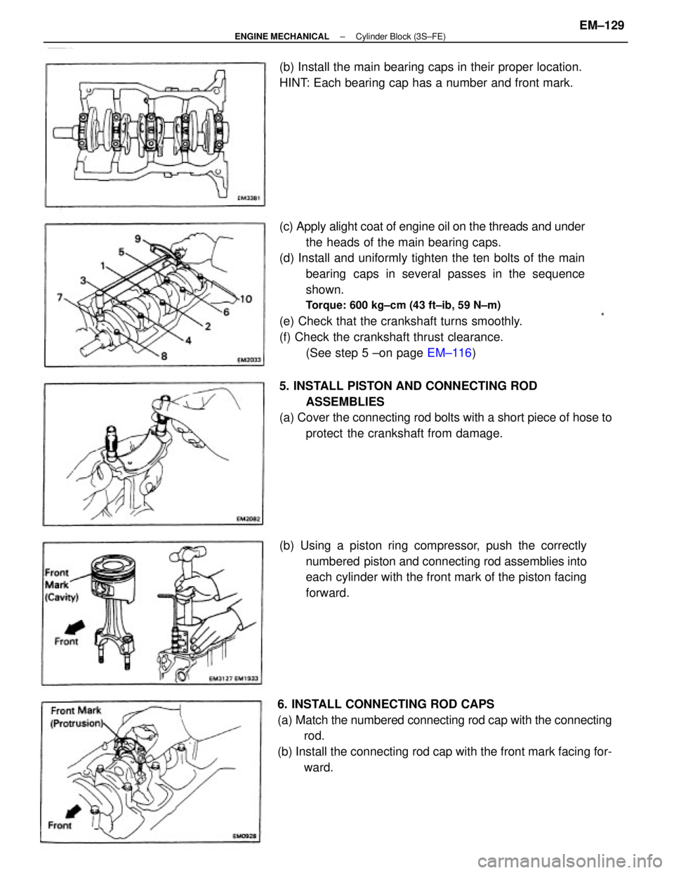
(c) Apply alight coat of engine oil on the threads and under
the heads of the main bearing caps.
(d) Install and uniformly tighten the ten bolts of the main
bearing caps in several passes in the sequence
shown.
Torque: 600 kg±cm (43 ft±ib, 59 N±m)
(e) Check that the crankshaft turns smoothly.
(f) Check the crankshaft thrust clearance.
(See step 5 ±on page EM±116)
6. INSTALL CONNECTING ROD CAPS
(a) Match the numbered connecting rod cap with the connecting
rod.
(b) Install the connecting rod cap with the front mark facing for-
ward. (b) Using a piston ring compressor, push the correctly
numbered piston and connecting rod assemblies into
each cylinder with the front mark of the piston facing
forward. 5. INSTALL PISTON AND CONNECTING ROD
ASSEMBLIES
(a) Cover the connecting rod bolts with a short piece of hose to
protect the crankshaft from damage. (b) Install the main bearing caps in their proper location.
HINT: Each bearing cap has a number and front mark.
± ENGINE MECHANICALCylinder Block (3S±FE)EM±129
Page 1307 of 2389
(c) Apply a light of engine oil on the threads and under the
nuts of the connecting rod cap.
(d) Install and alternately tighten the nuts of the connect-
ing rod cap in several passes.
Torque: 500 kg±cm (36 ft±Ib, 49 N±m)
(e) Check that the crankshaft turns smoothly.
M Check the connecting rod thrust clearance.
(See step 2 on page EM±114)
7. INSTALL REAR OIL SEAL RETAINER
Install a new gasket and the retainer with the six bolts.
Torque: 95 kg±cm (82 in.±Ib, 9.3 N±m)
± ENGINE MECHANICALCylinder Block (3S±FE)EM±130
Page 1315 of 2389

32. INSTALL BATTERY
33. FILL WITH ENGINE COOLANT (See page CO±5)
Capacity (w/ Heater):
M/T 6.4 liters (6.8 US qts, 5.6 Imp. qts)
A/T (2WD) 6.3 liters (6.7 US qts, 5.5 Imp. qts)
A/T (4WD) 6.8 liters (7.2 US qts, 6.0 Imp. qts)
34. FILL WITH ENGINE OIL (See page LU±8)
Capacity:
Drain and refill
w/ Oil filter change
3.9 liters (4.1 US qts, 3.4 Imp. qts)
w/o Oil filter change
3.7 liters (3.9 US qts, 3.3 Imp. qts)
Dry fill 4.3 liters (4.5 US qts, 3.8 Imp. qts)
35. START ENGINE AND CHECK FOR LEAKS
36. PERFORM ENGINE ADJUSTMENT
(a) Adjust the alternator drive belt.
(See page CH±3)
Drive belt tension:
w/ A/C New belt 175 + 5 lb
Used belt 130 + 10 lb
w/o A/C New belt 125 + 25 lb
Used belt 95 + 20 lb
(b) Adjust the PS drive belt.
Drive belt tension: New belt 125 + 25 lb
Used belt 80 + 20 lb
(c) Adjust the ignition timing.
(See steps 7 to 10 on pages IG±16 and 17)
Ignition timing:
10° BTDC @ idle
(w/ Terminals TE 1 and E1 connected)
(d) Adjust the valve. clearance. (See page EM±11)
Valve clearance:
Intake 0.19 ± 0.29 mm (0.007 ± 0.011 in.)
Exhaust 0.28 ± 0.38 mm (0.011 ± 0.015 in.)
37. INSTALL HOOD
38. PERFORM ROAD TEST
Check for abnormal noise, shock, slippage, correct shift
points and smooth operation.
39. RECHECK ENGINE COOLANT AND ENGINE OIL
LEVELS
± ENGINE MECHANICALCylinder Block (3S±FE)EM±138
Page 1324 of 2389
2. CHECK CONNECTING ROD THRUST CLEARANCE
Using a dial indicator, measure the thrust clearance while
moving the connecting rod back and forth.
Standard thrust clearance: 0.150 ± 0.330 mm
(0.0059 ± 0.0130 in.)
Maximum thrust clearance: 0.38 mm (0.0150 in.)
If the thrust clearance is greater than maximum, replace the
connecting rod assembly. If necessary, replace the crank-
shaft.
3. REMOVE CONNECTING ROD CAPS AND CHECK OIL
CLEARANCE
(a) Using a punch or numbering stamp, place the rnatchmarks
on the connecting rod and cap to ensure correct reas-
sembly.
(c) Using a plastic±faced hammer, lightly tap the connect-
ing rod bolts and lift off the connecting rod cap.
HINT: Keep the lower bearing inserted with the connect-
ing cap.
DISASSEMBLY OF CYLINDER BLOCK
(See page EM±139)
1. REMOVE REAR OIL SEAL RETAINER
Remove the six bolts and retainer.
(b) Using SST, remove the connecting rod cap nuts.
SST 09011±38121
± ENGINE MECHANICALCylinder Block (2VZ±FE)EM±147
Page 1325 of 2389
(i) Remove the connecting rod cap.
(j) Measure the Plastigage at widest point.
Standard oil clearance:
STD 0.028 ± 0.065 mm
(0.0011 ± 0.0026 in.)
U/S 0.25 0.027 ± 0.080 mm
(0.0011 ± 0.0031 in.)
Maximum oil clearance: 0.08 mm (0.0031 in.)
If the oil clearance is greater than maximum, replace
the bearings. If necessary, grind or replace the crank-
shaft. (e) Clean the crank pin and bearing.
(f) Check the crank pin and bearing for pitting and scratches.
If the crank pin or bearing is damaged, replace the bearing.
If necessary, grind or replace the crankshaft.
(h) Install the connecting rod cap.
(See step 6 on page EM±165)
Torque: 1st 250 kg±cm (18 ft±ib, 25 N±m)
2nd turns 90°
NOTICE: Do not turn the crankshaft
(d) Cover the connecting rod bolts with a short piece of
hose to protect the crankshaft from damage.
(g) Lay a strip of Plastigage across the crank pin.
± ENGINE MECHANICALCylinder Block (2VZ±FE)EM±148
Page 1326 of 2389

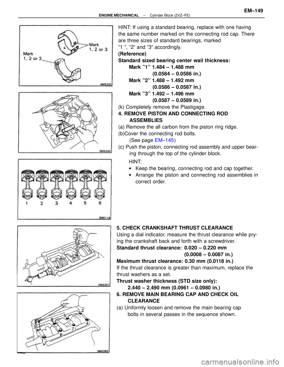
HINT: If using a standard bearing, replace with one having
the same number marked on the connecting rod cap. There
are three sizes of standard bearings, marked
º1 º, º2º and º3º accordingly.
(Reference)
Standard sized bearing center wail thickness:
Mark º1º 1.484 ± 1.488 mm
(0.0584 ± 0.0586 in.)
Mark º2º 1.488 ± 1.492 mm
(0.0586 ± 0.0587 in.)
Mark º3º 1.492 ± 1.496 mm
(0.0587 ± 0.0589 in.)
(k) Completely remove the Plastigage.
4. REMOVE PISTON AND CONNECTING ROD
ASSEMBLIES
(a) Remove the all carbon from the piston ring ridge.
(b)Cover the connecting rod bolts.
(See page EM±145)
(c) Push the piston, connecting rod assembly and upper bear-
ing through the top of the cylinder block.
5. CHECK CRANKSHAFT THRUST CLEARANCE
Using a dial indicator, measure the thrust clearance while pry-
ing the crankshaft back and forth with a screwdriver.
Standard thrust clearance: 0.020 ± 0.220 mm
(0.0008 ± 0.0087 in.)
Maximum thrust clearance: 0.30 mm (0.0118 in.)
If the thrust clearance is greater than maximum, replace the
thrust washers as a set.
Thrust washer thickness (STD size only):
2.440 ± 2.490 mm (0.0961 ± 0.0980 in.)
6. REMOVE MAIN BEARING CAP AND CHECK OIL
CLEARANCE
(a) Uniformly loosen and remove the main bearing cap
bolts in several passes in the sequence shown.HINT:
wKeep the bearing, connecting rod and cap together.
wArrange the piston and connecting rod assemblies in
correct order.
± ENGINE MECHANICALCylinder Block (2VZ±FE)EM±149
Page 1327 of 2389

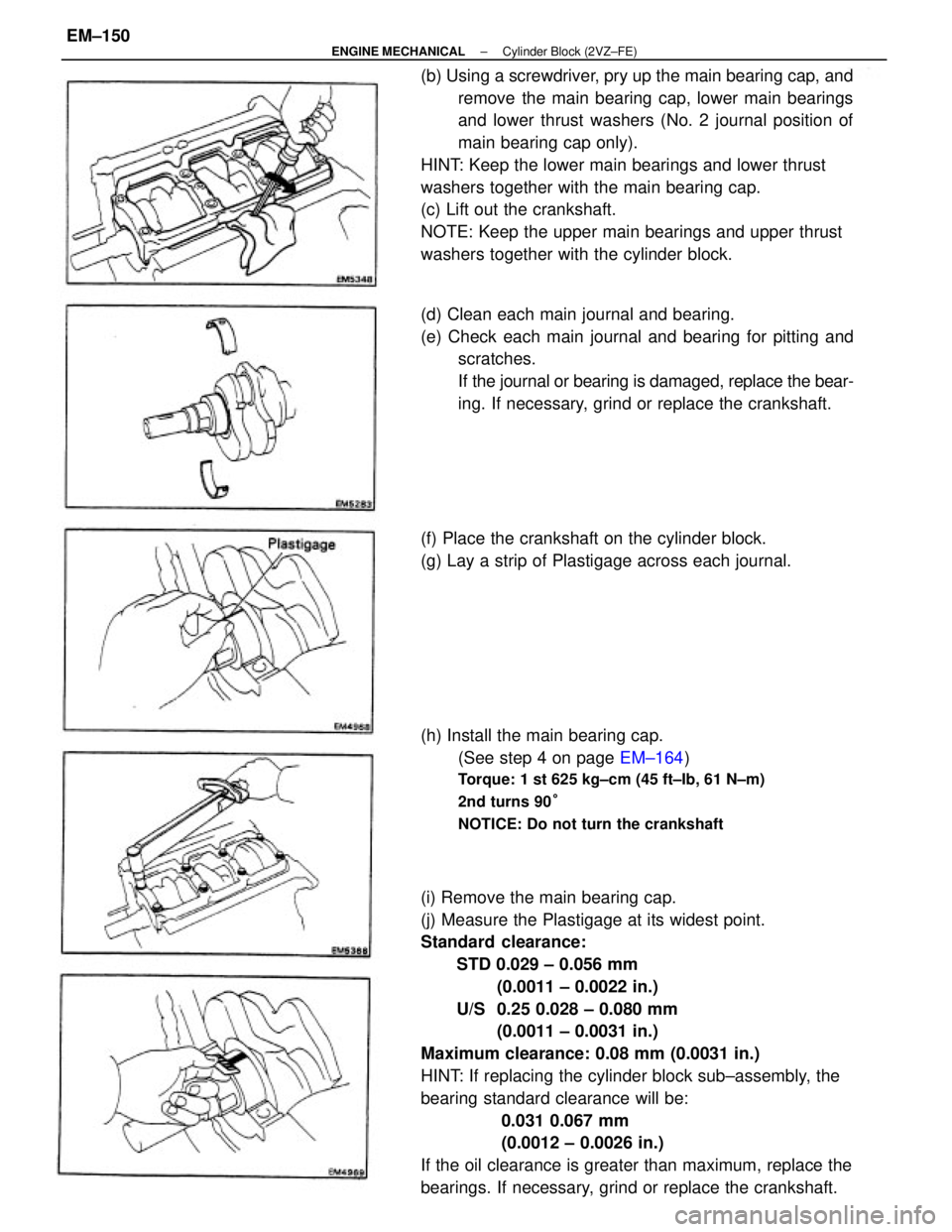
(i) Remove the main bearing cap.
(j) Measure the Plastigage at its widest point.
Standard clearance:
STD 0.029 ± 0.056 mm
(0.0011 ± 0.0022 in.)
U/S 0.25 0.028 ± 0.080 mm
(0.0011 ± 0.0031 in.)
Maximum clearance: 0.08 mm (0.0031 in.)
HINT: If replacing the cylinder block sub±assembly, the
bearing standard clearance will be:
0.031 0.067 mm
(0.0012 ± 0.0026 in.)
If the oil clearance is greater than maximum, replace the
bearings. If necessary, grind or replace the crankshaft. (b) Using a screwdriver, pry up the main bearing cap, and
remove the main bearing cap, lower main bearings
and lower thrust washers (No. 2 journal position of
main bearing cap only).
HINT: Keep the lower main bearings and lower thrust
washers together with the main bearing cap.
(c) Lift out the crankshaft.
NOTE: Keep the upper main bearings and upper thrust
washers together with the cylinder block.
(d) Clean each main journal and bearing.
(e) Check each main journal and bearing for pitting and
scratches.
If the journal or bearing is damaged, replace the bear-
ing. If necessary, grind or replace the crankshaft.
(h) Install the main bearing cap.
(See step 4 on page EM±164)
Torque: 1 st 625 kg±cm (45 ft±Ib, 61 N±m)
2nd turns 90°
NOTICE: Do not turn the crankshaft
(f) Place the crankshaft on the cylinder block.
(g) Lay a strip of Plastigage across each journal.
± ENGINE MECHANICALCylinder Block (2VZ±FE)EM±150
Page 1330 of 2389
DISASSEMBLY OF PISTON AND
CONNECTING ROD ASSEMBLIES
1. CHECK FIT BETWEEN PISTON AND PISTON PIN
Try to move the piston back and forth on the piston pin.
If any movement is felt, replace the piston and pin as a set.6. REMOVE CYLINDER RIDGE
If the wear is less than 0.2 mm (0.008 in.), use a ridge ream-
er to machine the piston ring ridge at the top of the cylinder.
2. REMOVE PISTON RINGS
(a) Using a piston ring expander, remove the two compres-
sion rings.
(b) Remove the two side rails and oil ring expander by
hand.
HINT: Arrange the rings in correct order only.
± ENGINE MECHANICALCylinder Block (2VZ±FE)EM±153