Page 1204 of 2389
INSPECTION OF TIMING BELT COMPONENTS
1. INSPECT TIMING BELT
NOTICE:
wDo not bend, twist or turn the timing belt inside out.
wDo not allow the timing belt to come into contact with
oil, water or steam.
wDo not utilize timing belt tension when installing or
removing the mount bolt of the camshaft timing pulley.
If there are any defects as shown in the figures, check
the following points:
(a) Premature parting
wCheck for proper installation.
wCheck the timing cover gasket for damage and proper
installation. 21. REMOVE CRANKSHAFT TIMING PULLEY
If the pulley cannot be removed by hand, use two screwdriv-
ers.
HINT: Position shop rags as shown to prevent damage.
22. REMOVE OIL PUMP PULLEY
Using SST, remove the nut and pulley.
SST 09616±30011
(b) If the belt teeth are cracked or damaged, check to see
if either the camshaft, water pump is locked.
EM3338
± ENGINE MECHANICALTiming Belt (3S±FE)EM±27
Page 1206 of 2389
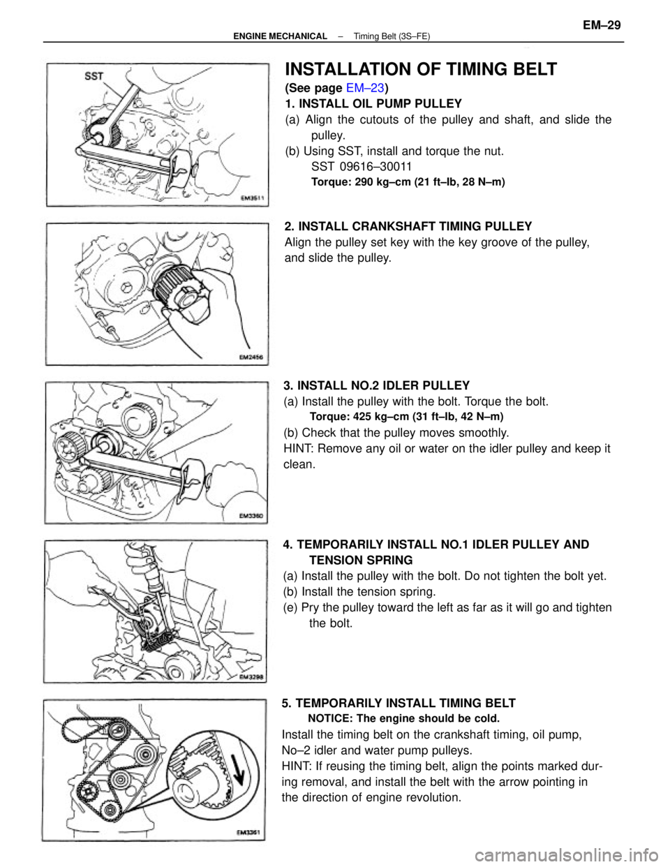
INSTALLATION OF TIMING BELT
(See page EM±23)
1. INSTALL OIL PUMP PULLEY
(a) Align the cutouts of the pulley and shaft, and slide the
pulley.
(b) Using SST, install and torque the nut.
SST 09616±30011
Torque: 290 kg±cm (21 ft±Ib, 28 N±m)
4. TEMPORARILY INSTALL NO.1 IDLER PULLEY AND
TENSION SPRING
(a) Install the pulley with the bolt. Do not tighten the bolt yet.
(b) Install the tension spring.
(e) Pry the pulley toward the left as far as it will go and tighten
the bolt.
5. TEMPORARILY INSTALL TIMING BELT
NOTICE: The engine should be cold.
Install the timing belt on the crankshaft timing, oil pump,
No±2 idler and water pump pulleys.
HINT: If reusing the timing belt, align the points marked dur-
ing removal, and install the belt with the arrow pointing in
the direction of engine revolution.3. INSTALL NO.2 IDLER PULLEY
(a) Install the pulley with the bolt. Torque the bolt.
Torque: 425 kg±cm (31 ft±Ib, 42 N±m)
(b) Check that the pulley moves smoothly.
HINT: Remove any oil or water on the idler pulley and keep it
clean.2. INSTALL CRANKSHAFT TIMING PULLEY
Align the pulley set key with the key groove of the pulley,
and slide the pulley.
± ENGINE MECHANICALTiming Belt (3S±FE)EM±29
Page 1212 of 2389
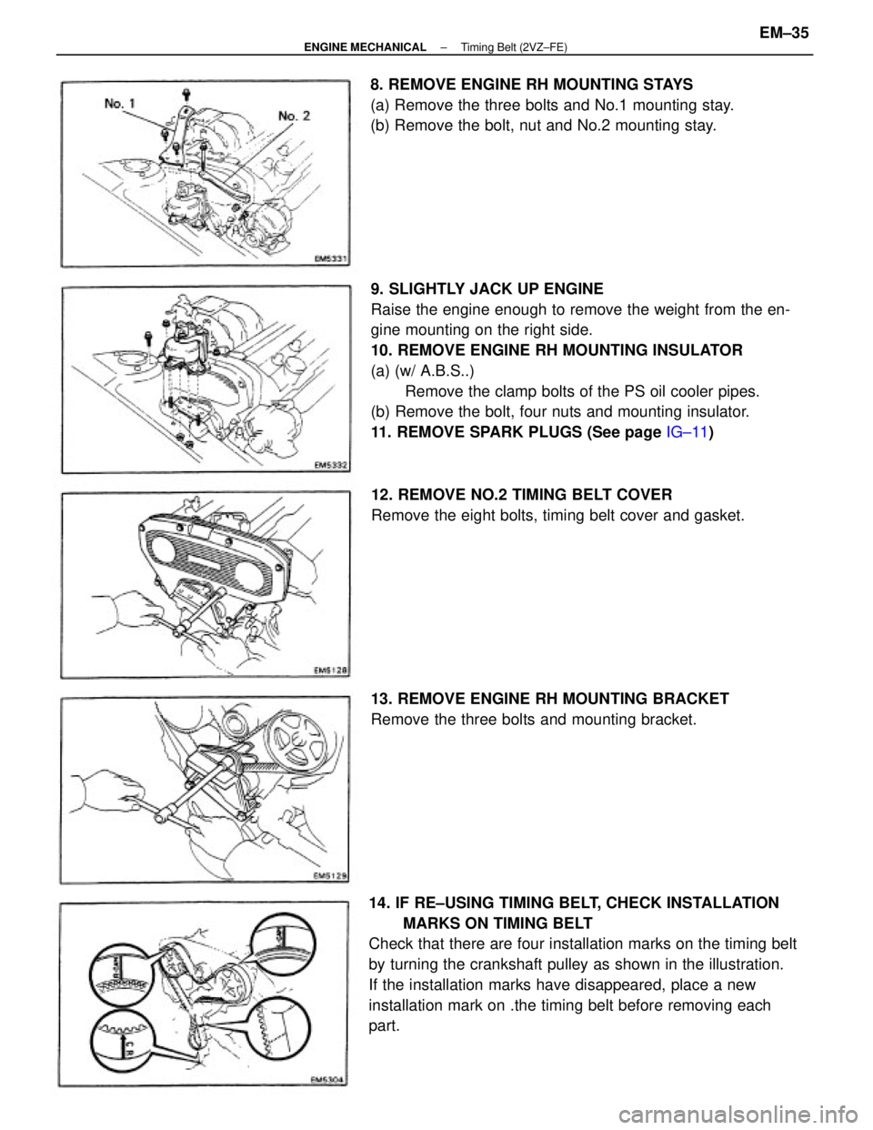
9. SLIGHTLY JACK UP ENGINE
Raise the engine enough to remove the weight from the en-
gine mounting on the right side.
10. REMOVE ENGINE RH MOUNTING INSULATOR
(a) (w/ A.B.S..)
Remove the clamp bolts of the PS oil cooler pipes.
(b) Remove the bolt, four nuts and mounting insulator.
11. REMOVE SPARK PLUGS (See page IG±11)
14. IF RE±USING TIMING BELT, CHECK INSTALLATION
MARKS ON TIMING BELT
Check that there are four installation marks on the timing belt
by turning the crankshaft pulley as shown in the illustration.
If the installation marks have disappeared, place a new
installation mark on .the timing belt before removing each
part.8. REMOVE ENGINE RH MOUNTING STAYS
(a) Remove the three bolts and No.1 mounting stay.
(b) Remove the bolt, nut and No.2 mounting stay.
12. REMOVE NO.2 TIMING BELT COVER
Remove the eight bolts, timing belt cover and gasket.
13. REMOVE ENGINE RH MOUNTING BRACKET
Remove the three bolts and mounting bracket.
± ENGINE MECHANICALTiming Belt (2VZ±FE)EM±35
Page 1217 of 2389
INSPECTION OF TIMING BELT
COMPONENTS
1. INSPECT TIMING BELT
NOTICE:
wDo not bend, twist or turn the timing belt inside out.
wDo not allow the timing belt to come into contact
with oil, water or steam.
wDo not utilize timing belt tension when installing or removing
the mount bolt of the camshaft timing pulley.
If there are any defects as shown in the figures, check the
following points:
(a) Premature parting
wCheck for proper installation.
wCheck the timing cover gasket for damage and proper instal-
lation.
(c) If there are cracks or noticeable wear on the belt face,
check to see if there are nicks on the side of the idler
pulley lock and water pump.
(d) If there is wear or damage on only one side of the belt,
check the belt guide 'and the alignment of each
pulley. (b) If the belt teeth are cracked or damaged, check to see
if either camshaft is locked.
± ENGINE MECHANICALTiming Belt (2VZ±FE)EM±40
Page 1218 of 2389
3. INSPECT TIMING BELT TENSIONER
(a) Visually check tensioner for oil leakage.
HINT: If there is only the faintest trace of oil on the seal on
the push rod side, the tensioner is all right.
If leakage is found, replace the tensioner. (e) If there is noticeable wear on the belt teeth, check tim-
ing cover for damage and check for correct gasket
installation. Check for foreign material on the pulley
teeth.
If necessary, replace the timing belt.
(c) Measure the protrusion of the push rod from the hous-
ing end.
Protrusion: 10.5 ± 11.5 mm (0.413 ± 0.453 in.)
If the protrusion is not as specified, replace the ten-
sioner. (b) Hold the tensioner with both hands and push the push
rod strongly against the floor or wall to check that it
doesn't move.
If the push rod moves, replace the tensioner. 2. INSPECT IDLER PULLEYS
Check the turning smoothness of the idler pulley.
If necessary, replace the idler pulley.
± ENGINE MECHANICALTiming Belt (2VZ±FE)EM±41
Page 1219 of 2389
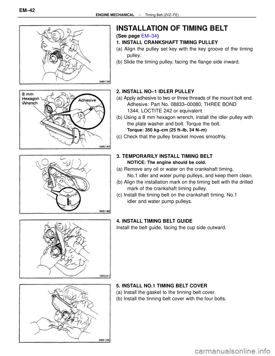
2. INSTALL NO±1 IDLER PULLEY
(a) Apply adhesive to two or three threads of the mount bolt end.
Adhesive: Part No. 08833±00080, THREE BOND
1344, LOCTITE 242 or equivalent
(b) Using a 8 mm hexagon wrench, install the idler pulley with
the plate washer and bolt. Torque the bolt.
Torque: 350 kg±cm (25 ft±Ib, 34 N±m)
(c) Check that the pulley bracket moves smoothly.
3. TEMPORARILY INSTALL TIMING BELT
NOTICE: The engine should be cold.
(a) Remove any oil or water on the crankshaft timing,
No.1 idler and water pump pulleys, and keep them clean.
(b) Align the installation mark on the timing belt with the drilled
mark of the crankshaft timing pulley.
(c) Install the timing belt on the crankshaft timing, No.1
idler and water pump pulleys.
INSTALLATION OF TIMING BELT
(See page EM±34)
1. INSTALL CRANKSHAFT TIMING PULLEY
(a) Align the pulley set key with the key groove of the timing
pulley.
(b) Slide the timing pulley, facing the flange side inward.
5. INSTALL NO.1 TIMING BELT COVER
(a) Install the gasket to the tinning belt cover.
(b) Install the tinning belt cover with the four bolts.4. INSTALL TIMING BELT GUIDE
Install the belt guide, facing the cup side outward.
± ENGINE MECHANICALTiming Belt (2VZ±FE)EM±42
Page 1221 of 2389
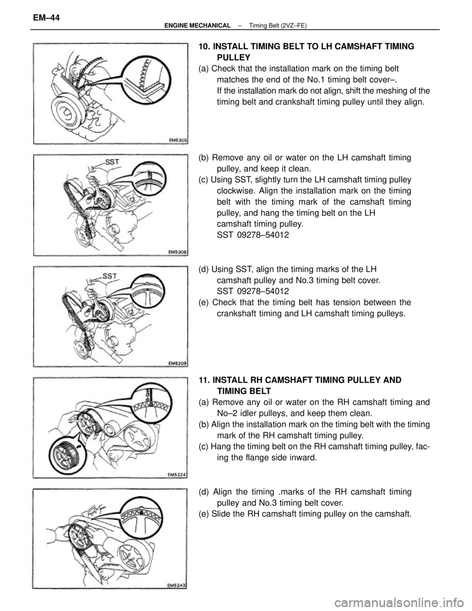
11. INSTALL RH CAMSHAFT TIMING PULLEY AND
TIMING BELT
(a) Remove any oil or water on the RH camshaft timing and
No±2 idler pulleys, and keep them clean.
(b) Align the installation mark on the timing belt with the timing
mark of the RH camshaft timing pulley.
(c) Hang the timing belt on the RH camshaft timing pulley, fac-
ing the flange side inward. (b) Remove any oil or water on the LH camshaft timing
pulley, and keep it clean.
(c) Using SST, slightly turn the LH camshaft timing pulley
clockwise. Align the installation mark on the timing
belt with the timing mark of the camshaft timing
pulley, and hang the timing belt on the LH
camshaft timing pulley.
SST 09278±54012 10. INSTALL TIMING BELT TO LH CAMSHAFT TIMING
PULLEY
(a) Check that the installation mark on the timing belt
matches the end of the No.1 timing belt cover±.
If the installation mark do not align, shift the meshing of the
timing belt and crankshaft timing pulley until they align.
(d) Using SST, align the timing marks of the LH
camshaft pulley and No.3 timing belt cover.
SST 09278±54012
(e) Check that the timing belt has tension between the
crankshaft timing and LH camshaft timing pulleys.
(d) Align the timing .marks of the RH camshaft timing
pulley and No.3 timing belt cover.
(e) Slide the RH camshaft timing pulley on the camshaft.
± ENGINE MECHANICALTiming Belt (2VZ±FE)EM±44
Page 1231 of 2389
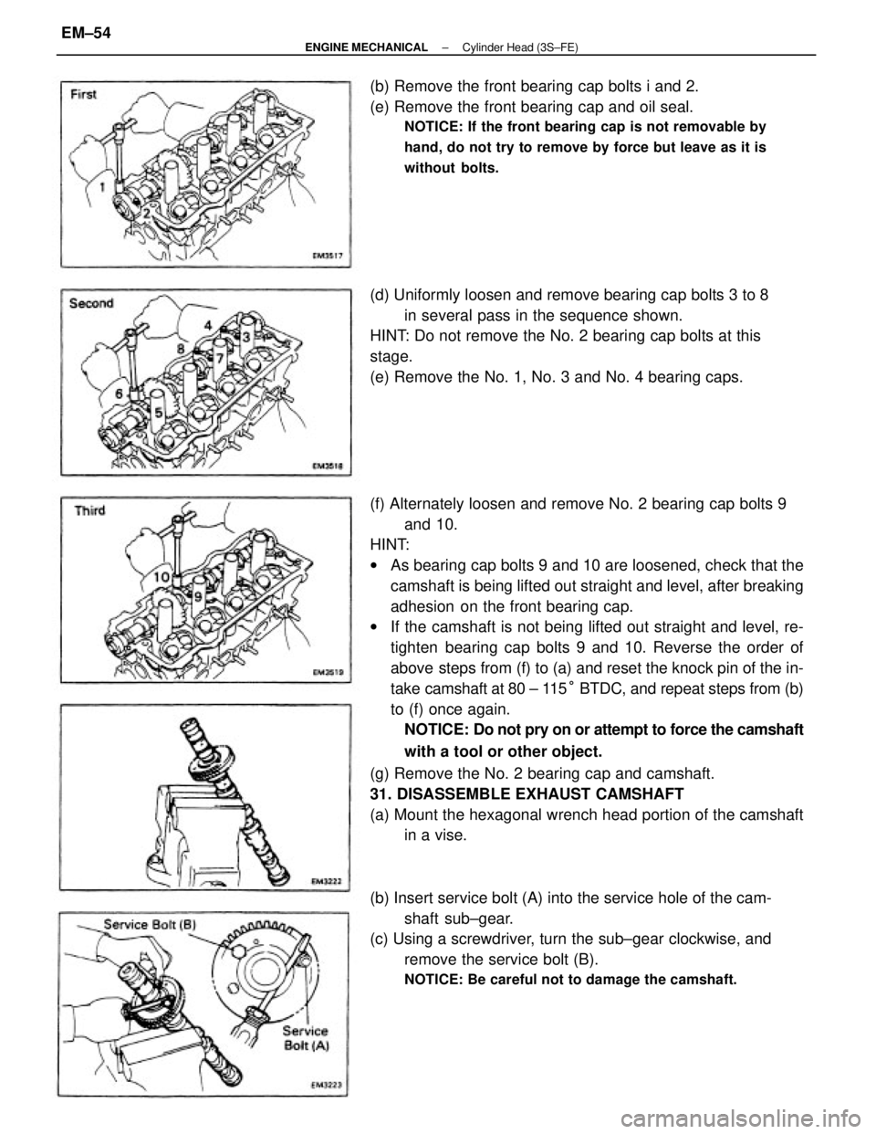
(f) Alternately loosen and remove No. 2 bearing cap bolts 9
and 10.
HINT:
wAs bearing cap bolts 9 and 10 are loosened, check that the
camshaft is being lifted out straight and level, after breaking
adhesion on the front bearing cap.
wIf the camshaft is not being lifted out straight and level, re-
tighten bearing cap bolts 9 and 10. Reverse the order of
above steps from (f) to (a) and reset the knock pin of the in-
take camshaft at 80 ± 115° BTDC, and repeat steps from (b)
to (f) once again.
NOTICE: Do not pry on or attempt to force the camshaft
with a tool or other object.
(g) Remove the No. 2 bearing cap and camshaft.
31. DISASSEMBLE EXHAUST CAMSHAFT
(a) Mount the hexagonal wrench head portion of the camshaft
in a vise.
(b) Insert service bolt (A) into the service hole of the cam-
shaft sub±gear.
(c) Using a screwdriver, turn the sub±gear clockwise, and
remove the service bolt (B).
NOTICE: Be careful not to damage the camshaft.
(d) Uniformly loosen and remove bearing cap bolts 3 to 8
in several pass in the sequence shown.
HINT: Do not remove the No. 2 bearing cap bolts at this
stage.
(e) Remove the No. 1, No. 3 and No. 4 bearing caps. (b) Remove the front bearing cap bolts i and 2.
(e) Remove the front bearing cap and oil seal.
NOTICE: If the front bearing cap is not removable by
hand, do not try to remove by force but leave as it is
without bolts.
± ENGINE MECHANICALCylinder Head (3S±FE)EM±54