Page 785 of 2389
Low Oil Pressure Warning
INSPECTION OF PRESSURE WARNING
1. INSPECT WARNING LIGHT OPERATION
(a) Disconnect the connector from the pressure switch
and ground the connector on the wire harness side.
(b) Turn the ignition switch ON, check that t he warning
light lights.
If the warning light does not light, test the bulb.
2. INSPECT PRESSURE SWITCH OPERATION
(a) Disconnect the connector from the switch.
(b) Check that there is continuity between terminal and
ground with the engine stopped.
(c) Check that there is no continuity between terminal
and ground with the engine running.
HINT: Oil pressure should be over 0.3 kg/cm2 (4.3 psi, 29
kPa).
If operation is not as specified, replace the switch.If resistance value is not as specified, replace the send-
er gauge. 3. MEASURE SENDER GAUGE RESISTANCE
Measure the resistance between terminal and ground.
ater temperature oC
(OF)Resistance (�)
N i ppo nde nso Yazaki
± BODY ELECTRICAL SYSTEMCombination MeterBE±39
Page 789 of 2389

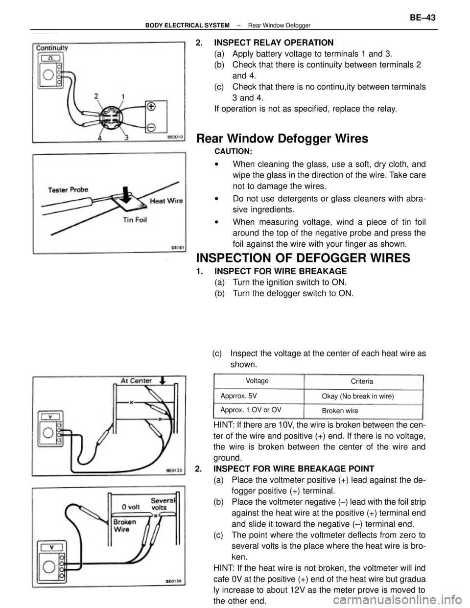
Rear Window Defogger Wires
CAUTION:
wWhen cleaning the glass, use a soft, dry cloth, and
wipe the glass in the direction of the wire. Take care
not to damage the wires.
wDo not use detergents or glass cleaners with abra-
sive ingredients.
wWhen measuring voltage, wind a piece of tin foil
around the top of the negative probe and press the
foil against the wire with your finger as shown.
INSPECTION OF DEFOGGER WIRES
1. INSPECT FOR WIRE BREAKAGE
(a) Turn the ignition switch to ON.
(b) Turn the defogger switch to ON.
HINT: If there are 10V, the wire is broken between the cen-
ter of the wire and positive (+) end. If there is no voltage,
the wire is broken between the center of the wire and
ground.
2. INSPECT FOR WIRE BREAKAGE POINT
(a) Place the voltmeter positive (+) lead against the de-
fogger positive (+) terminal.
(b) Place the voltmeter negative (±) lead with the foil strip
against the heat wire at the positive (+) terminal end
and slide it toward the negative (±) terminal end.
(c) The point where the voltmeter deflects from zero to
several volts is the place where the heat wire is bro-
ken.
HINT: If the heat wire is not broken, the voltmeter will ind
cafe 0V at the positive (+) end of the heat wire but gradua
ly increase to about 12V as the meter prove is moved to
the other end. 2. INSPECT RELAY OPERATION
(a) Apply battery voltage to terminals 1 and 3.
(b) Check that there is continuity between terminals 2
and 4.
(c) Check that there is no continu,ity between terminals
3 and 4.
If operation is not as specified, replace the relay.
(c) Inspect the voltage at the center of each heat wire as
shown.
Okay (No break in wire)
Approx. 1 OV or OVApprrox. 5V
Broken wire Voltage
Criteria
± BODY ELECTRICAL SYSTEMRear Window DefoggerBE±43
Page 852 of 2389

PRECAUTIONS
1. Care must be taken to replace each part properly as it
could affect the performance of the brake system and re-
sult in a driving hazard. Replace the parts with parts of the
same part number or equivalent.
2. It is very important to keep parts and the area clean when
repairing the brake system.
Parking brake out of adjustment
Binding parking brake wire
Booster push rod out of adjustment
Tension or return spring faulty
Brake line restricted
Lining cracked or distorted
Pad cracked or distorted
Wheel cylinder or caliper piston sticking
Adjuster broken
Master cylinder faulty
Brake shoes distorted, linings worn or glazed
Brake pads distorted, worn or glazed
Drum or disc out of round
Tension or return spring faulty
Wheel cylinder faulty
Brake cylinder faulty
Piston frozen in brake cylinder
Brake pad stickingReplace brake shoes
Replace pads
Repair leak
Repair or replace master cylinder
Bleed brake system
Repair wheel cylinder
Repair cylinder
Repair brake cylinder
Repair or replace adjuster Air in brake system
Wheel cylinder faulty
Brake cylinder faulty
Piston seals worn or damaged
Rear brake automatic adjuster faulty
Adjust parking brake
Repair as necessary
Adjust push rod
Replace spring
Repair as necessary
Replace shoe
Replace pad
Repair as necessary
Replace pads
Replace drum or disc
Replace spring
Repair wheel cylinder
Repair cylinder
Repair cylinder
Replace padsInflate tires to proper pressure
Check for cause. Replace shoes
or pads
Replace brake shoes Linings worn
Brake pads worn
Leak in brake system
Master cylinder faulty
BR±18, 34
BR±18, 26
34
BR±26, 42
BR±26
BR±18, 34
BR±18, 34
BR±18, 34 Replace adjuster
Repair or replace master
cylinder
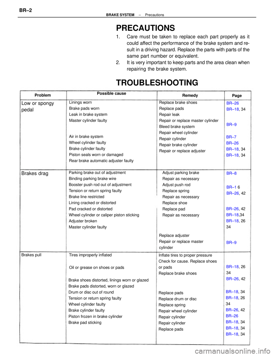
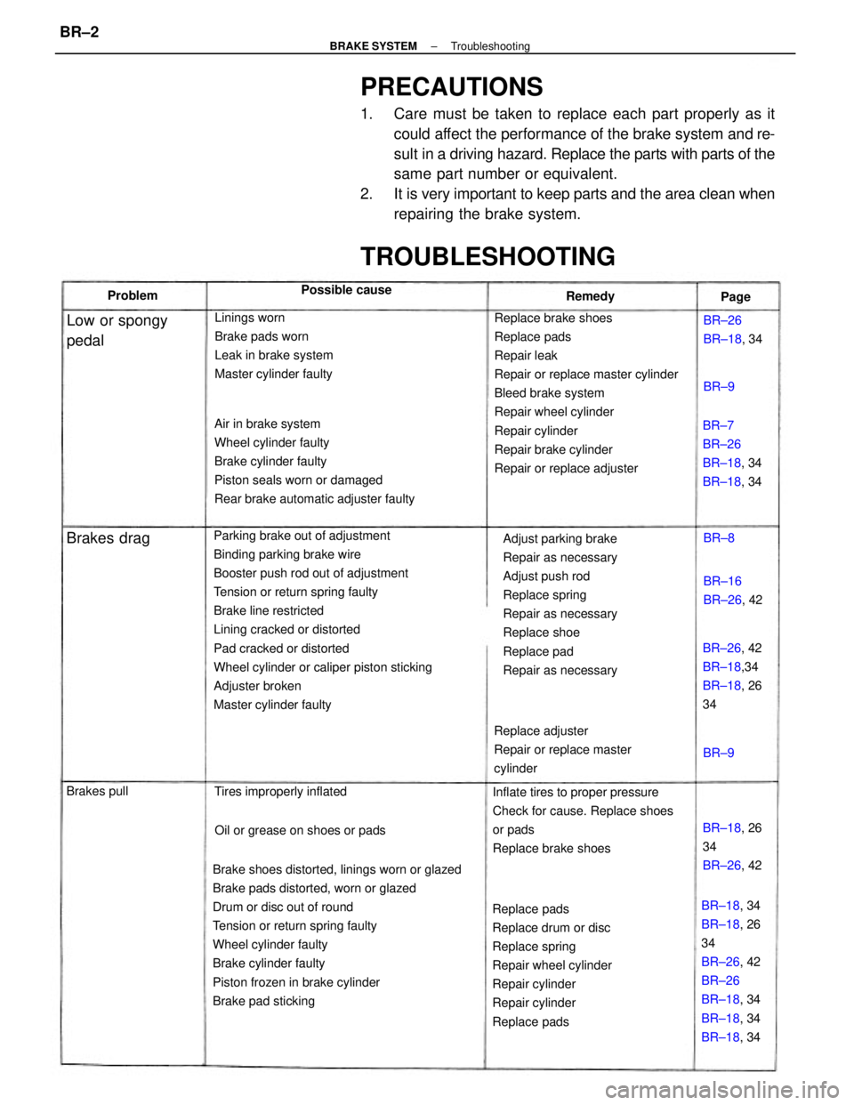
TROUBLESHOOTING
BR±7
BR±26
BR±18, 34
BR±18, 34
BR±26, 42
BR±18,34
BR±18, 26
34
Oil or grease on shoes or pads Tires improperly inflated
BR±18, 26
34
BR±26, 42
Low or spongy
pedalBR±26
BR±18, 34
BR±1 6
BR±26, 42 Possible cause
Brakes drag
Brakes pullRemedy Problem
Page
BR±8
BR±9BR±9
± BRAKE SYSTEMPrecautionsBR±2
Page 853 of 2389

PRECAUTIONS
1. Care must be taken to replace each part properly as it
could affect the performance of the brake system and re-
sult in a driving hazard. Replace the parts with parts of the
same part number or equivalent.
2. It is very important to keep parts and the area clean when
repairing the brake system.
Parking brake out of adjustment
Binding parking brake wire
Booster push rod out of adjustment
Tension or return spring faulty
Brake line restricted
Lining cracked or distorted
Pad cracked or distorted
Wheel cylinder or caliper piston sticking
Adjuster broken
Master cylinder faulty
Brake shoes distorted, linings worn or glazed
Brake pads distorted, worn or glazed
Drum or disc out of round
Tension or return spring faulty
Wheel cylinder faulty
Brake cylinder faulty
Piston frozen in brake cylinder
Brake pad stickingReplace brake shoes
Replace pads
Repair leak
Repair or replace master cylinder
Bleed brake system
Repair wheel cylinder
Repair cylinder
Repair brake cylinder
Repair or replace adjuster Air in brake system
Wheel cylinder faulty
Brake cylinder faulty
Piston seals worn or damaged
Rear brake automatic adjuster faulty
Adjust parking brake
Repair as necessary
Adjust push rod
Replace spring
Repair as necessary
Replace shoe
Replace pad
Repair as necessary
Replace pads
Replace drum or disc
Replace spring
Repair wheel cylinder
Repair cylinder
Repair cylinder
Replace padsInflate tires to proper pressure
Check for cause. Replace shoes
or pads
Replace brake shoes Linings worn
Brake pads worn
Leak in brake system
Master cylinder faulty
BR±18, 34
BR±18, 26
34
BR±26, 42
BR±26
BR±18, 34
BR±18, 34
BR±18, 34 Replace adjuster
Repair or replace master
cylinder
TROUBLESHOOTING
BR±7
BR±26
BR±18, 34
BR±18, 34
BR±26, 42
BR±18,34
BR±18, 26
34
Oil or grease on shoes or pads Tires improperly inflated
BR±18, 26
34
BR±26, 42
Low or spongy
pedalBR±26
BR±18, 34
BR±16
BR±26, 42 Possible cause
Brakes drag
Brakes pullRemedy Problem
Page
BR±8
BR±9BR±9
± BRAKE SYSTEMTroubleshootingBR±2
Page 854 of 2389

(Drum brake)
Brake shoes binding at backing plate ledges
Backing plate ledges worn
Loose or missing shoe hold±down spring
Loose set bolt at backing plate
(Disc brake)
Loose or missing pad support plate
Loose installation bolt
Wear on slide bushingBrake shoes distorted, linings worn or glazed,
drums worn
Brake pads distorted, worn or glazed
Piston frozen in brake cylinder
Brake booster faulty
Vacuum leaks
Brake line restricted
Caliper to wheel or rotor interference
Dust cover to rotor or backing plate to drum
interference
Other brake system components faultyReplace and lubricate ledges
Replace shoe hold±down spring
TightenReplace pads
Repair cylinder
Repair booster
Repair as necessary
Repair as necessary
Replace pad support plate
Tighten
Replace slide bushing
Replace or refinish drums or rotors if
heavily scored
Replace as required
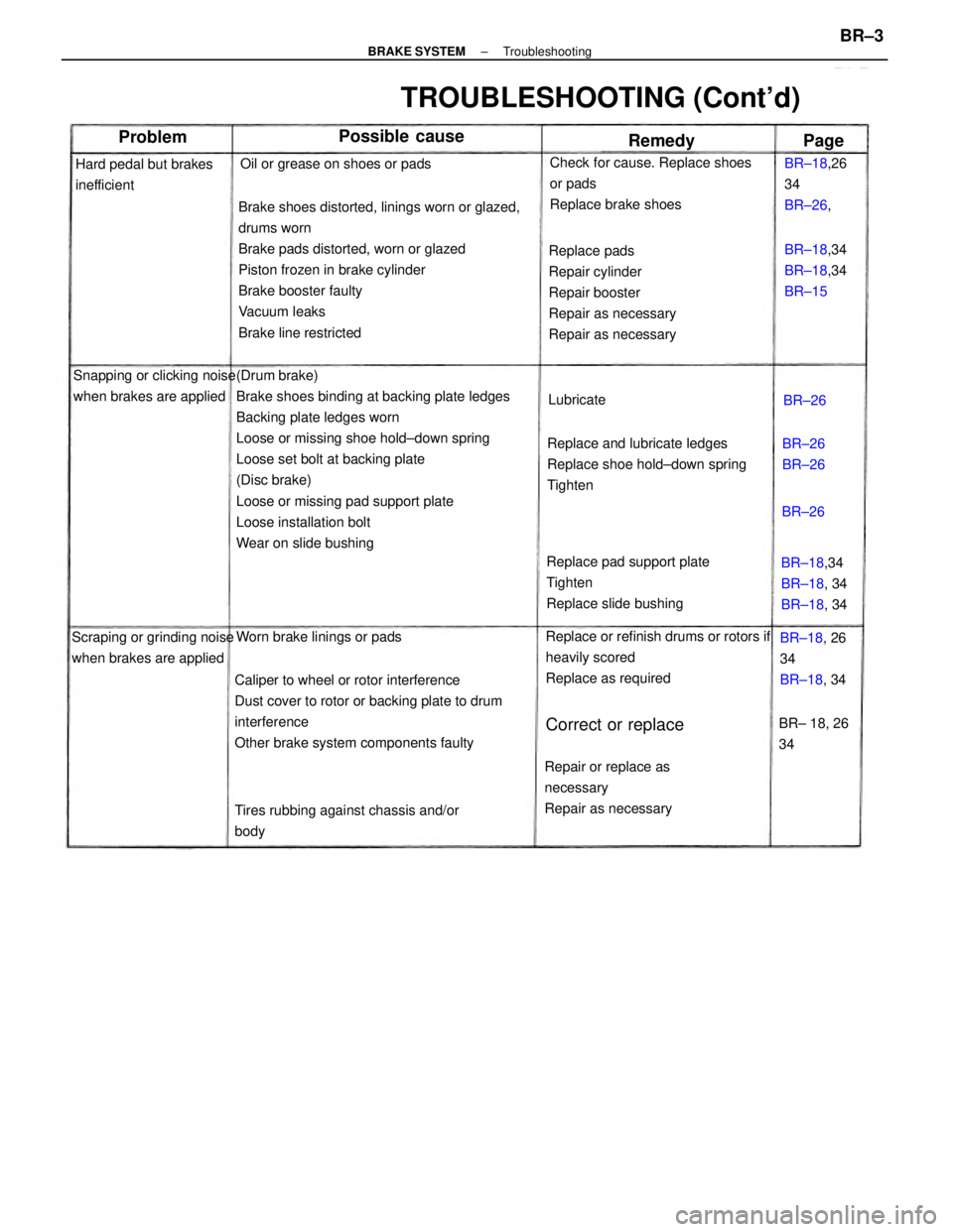
TROUBLESHOOTING (Cont'd)
Check for cause. Replace shoes
or pads
Replace brake shoes
Repair or replace as
necessary
Repair as necessary
Tires rubbing against chassis and/or
body Snapping or clicking noise
when brakes are applied
Scraping or grinding noise
when brakes are appliedOil or grease on shoes or pads
Hard pedal but brakes
inefficient
Worn brake linings or padsBR±18,34
BR±18, 34
BR±18, 34 BR±18,34
BR±18,34
BR±15 BR±18,26
34
BR±26,
BR±18, 26
34
BR±18, 34
Correct or replaceBR± 18, 26
34
Possible cause
BR±26
BR±26 Lubricate
Problem
Remedy
BR±26
Page
BR±26
± BRAKE SYSTEMTroubleshootingBR±3
Page 871 of 2389

8. INSTALL NEW PADS
(a) Install new pad wear indicator plate to inner pad.
NINT: Be sure the arrow on the pad wear indicator
plate is pointing i n the direction of the disc rotation.
(b) (Except 2VZ±FE Engine of w/ A.B.S.)
Install the one anti±squeal shim to the each pad.
(c) (For 2VZ±FE Engine of w/ A.B.S.)
Install the two anti±squeal shims to the each pad.
HINT: Apply disc brake grease to both side of the inner
anti±squeal shim of the outside pad.
(d) Install the pads onto each support plate.
NOTICE: Do not allow oil or grease to get on the
rubbing face.
(e) Install the two anti±squeal springs.
9. INSTALL CYLINDER
(a) Draw out a small amount of brake fluid from the reser-
voir.
(b) Press in piston with a hammer handle or an equiva-
lent.
HINT: Always change the pad on one wheel at a time as
there is a possibility of the opposite piston flying out.
(c) Insert the brake cylinder carefully ±so the boot is not
wedged. 5. CHECK ROTOR DISC THICKNESS
(See step 2 on page BR±23)
6. CHECK ROTOR DISC RUNOUT
(See step 3 on page BR±23)
7. INSTALL PAD SUPPORT PLATES
± BRAKE SYSTEMFront BrakeBR±20
Page 883 of 2389
8. CHECK OPERATION OF AUTOMATIC ADJUSTING
MECHANISM
(a) Move the parking brake lever of the rear shoe back
and forth, as shown. Check that the adjuster turns.
If the adjuster does not turn, check for incorrect installation
of the rear brakes.
(b) Adjust the adjuster length to the shortest possible
amount. 7. INSTALL FRONT SHOE
(a) Install the anchor spring between the front and rear
shoes.
(b) Set the front shoe in place with the end of the shoe
inserted in the wheel cylinder and the adjuster in
place.
(c) Using SST, install the shoe hold±down spring, cups
and pin.
SST 09718±00010
NOTICE: Do not allow oil or grease to get on the ru
bing face.
(c) Align the adjusting hole on the brake drum and largest
hole on the axle carrier, install the brake drum. (d) Using SST, connect the return spring.
SST 09703±30010
± BRAKE SYSTEMRear BrakeBR±32
Page 934 of 2389

(d) Jack up the front side of the vehicle slowly as shown.
HINT: When measuring the height, measure at the center
of the lower body or spoiler edge of the vehicle.
(e) Check that the warning light does not turn on.
(f) Jack down the vehicle and check that the warning
light blinking.
If the warning light turns on, inspect the deceleration se
sor installation. And if the sensor installation is ±OK, r
place the deceleration sensor.
(e) Drive the vehicle straight ahead at about 20 km/h
(12.4 mph) or more, depress the brake pedal strong±
ly.
(f) Check that the warning light light pattern changes af-
ter braking as shown.
If the operation is not as specified, inspect the deceleration
sensor installation. And if the sensor installation is OK, r
place the deceleration sensor. 5. INSPECT SENSOR OPERATION
(a) Drive the vehicle straight ahead at about 10 km/h l6.2
mph) or more, lightly depress the brake pedal.
(b) Check that there is no change in the warning light
light pattern.
(c) Drive the vehicle straight ahead at about 20 km/h
(12.4 mph) or more, depress the brake pedal a little
strong.
(d) Check that the warning light turns on while braking.
6. REMOVE SHORT PIN
(a) Stop the engine.
(b) Remove the short pin or wire from the Ts connector.
(c) Install the rubber cap to the Ts connector.
± BRAKE SYSTEMAnti±lock Brake System (A.B.S.)BR±83