Page 1034 of 2389
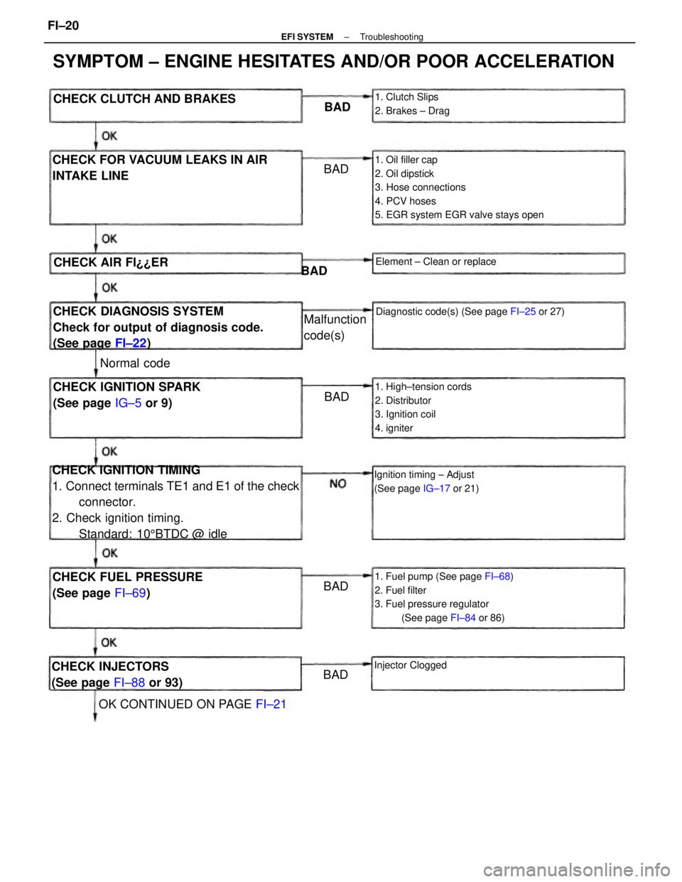
CHECK IGNITION TIMING
1. Connect terminals TE1 and E1 of the check
connector.
2. Check ignition timing.
Standard: 105BTDC @ idle
1. Oil filler cap
2. Oil dipstick
3. Hose connections
4. PCV hoses
5. EGR system EGR valve stays open
SYMPTOM ± ENGINE HESITATES AND/OR POOR ACCELERATION
1. Fuel pump (See page FI±68)
2. Fuel filter
3. Fuel pressure regulator
(See page FI±84 or 86)
CHECK DIAGNOSIS SYSTEM
Check for output of diagnosis code.
(See page FI±22) CHECK FOR VACUUM LEAKS IN AIR
INTAKE LINE
1. High±tension cords
2. Distributor
3. Ignition coil
4. igniterCHECK IGNITION SPARK
(See page IG±5 or 9)
CHECK FUEL PRESSURE
(See page FI±69)
Diagnostic code(s) (See page FI±25 or 27)
Ignition timing ± Adjust
(See page IG±17 or 21)
CHECK INJECTORS
(See page FI±88 or 93)
OK CONTINUED ON PAGE FI±21 CHECK CLUTCH AND BRAKES
1. Clutch Slips
2. Brakes ± Drag
Element ± Clean or replace
Malfunction
code(s)
Injector Clogged
CHECK AIR FI¿¿ER
Normal codeBAD
BADBAD
BADBAD BAD
± EFI SYSTEMTroubleshootingFI±20
Page 1041 of 2389
(CALIF.)
wWhen air±fuel ratio feed±
back correction value or adap-
tive control value continues at
the upper (lean)
or lower (rich) limit for a certain
period of time or adaptive con-
trol value is not renewed for a
certain period of time.
wWhen feedback frequency of
air±fuel ratio feed±
back correction or adaptive
control is abnormally
high during feedback condition.
(Others)
wOxygen sensor outputs a lean
signal continuously for several
seconds during air±fuel ratio
feedback correction.
wOpen circuit in oxygen sensor
signal (OX).wWater temp. sensor
wInjector circuit
wInjector
wFuel line pressure
wAir flow meter
wAir intake system
wOxygen sensor circuits
wOxygen sensors
wIgnition system
wECU During air±fuel ratio feedback
correction, voltage output from the
main oxygen sensor does exceed a
set value on the lean side and the
rich side continuously for a certain
period.
Water temp. sensor
wInjector circuit
wInjector
wFuel line pressure
wAir flow meter
wCold start injector
wECU wMain oxygen heater circuit
wMain oxygen sensor heater
wECU wIgniter and ignition coil circuit
wIgniter and ignition coil
wECU
wIntake air temp. sensor circuit
wIntake air temp. sensor
wECU Open or short circuit in main oxygen
sensor heater signal
(HT).No NE signal to ECU when the en-
gine speed is above 1,000
rpm.wDistributor circuit
wDistributor
wStarter signal circuit
wECU
wMain oxygen sensor circuit
wMain oxygen sensor
wECU No NE or G signal to ECU
within 2 seconds after engine has
been cranked.
wWater temp. sensor circuit
wWater temp. sensor
wECU
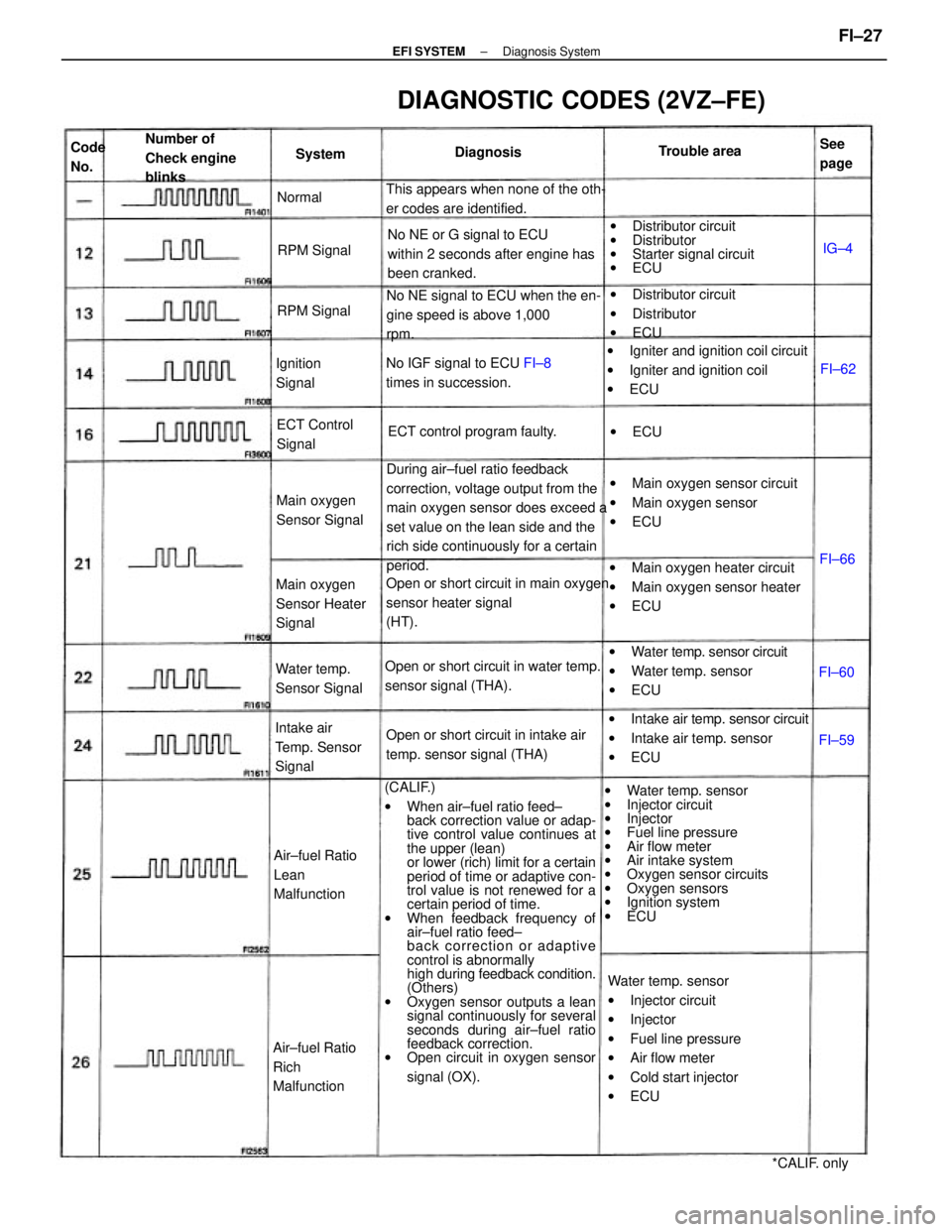
DIAGNOSTIC CODES (2VZ±FE)
Open or short circuit in water temp.
sensor signal (THA).
Open or short circuit in intake air
temp. sensor signal (THA) This appears when none of the oth-
er codes are identified.
wDistributor circuit
wDistributor
wECU
No IGF signal to ECU FI±8
times in succession.
Intake air
Temp. Sensor
Signal
Air±fuel Ratio
Lean
Malfunction Number of
Check engine
blinks
Air±fuel Ratio
Rich
MalfunctionMain oxygen
Sensor Heater
SignalECT control program faulty.
Main oxygen
Sensor Signal
Water temp.
Sensor SignalECT Control
Signal
*CALIF. only Ignition
SignalTrouble area
RPM Signal
RPM SignalDiagnosisSee
page Code
No.System
Normal
wECU
FI±60FI±66
FI±59FI±62IG±4
± EFI SYSTEMDiagnosis SystemFI±27
Page 1064 of 2389
No voltage between ECU terminals No. 10 and/or No. 20 and
E01 and/or E02. (IG SW ON)
Check that there is voltage between ECU terminal No. 10
and/or No. 20 and body ground.
Check resistance of magnetic coil in each injector.
STD resistance: Approx. 13.8 11Check wiring between ECU terminal E01 and/or
E02 and body ground.
Check wiring between ECU
terminal No. 10 and/or No. 20
and battery.Check fuse, fusible link and
ignition switch.
Repair or replace. Repair or replace.
Repair or replace. Try another ECU.
Replace injector. STD voltage
No voltage
IG SW ONCondition
TerminalsTrouble
BAD BAD
BADBAD No.
± EFI SYSTEMTroubleshooting with Volt OhmmeterFI±40
Page 1074 of 2389
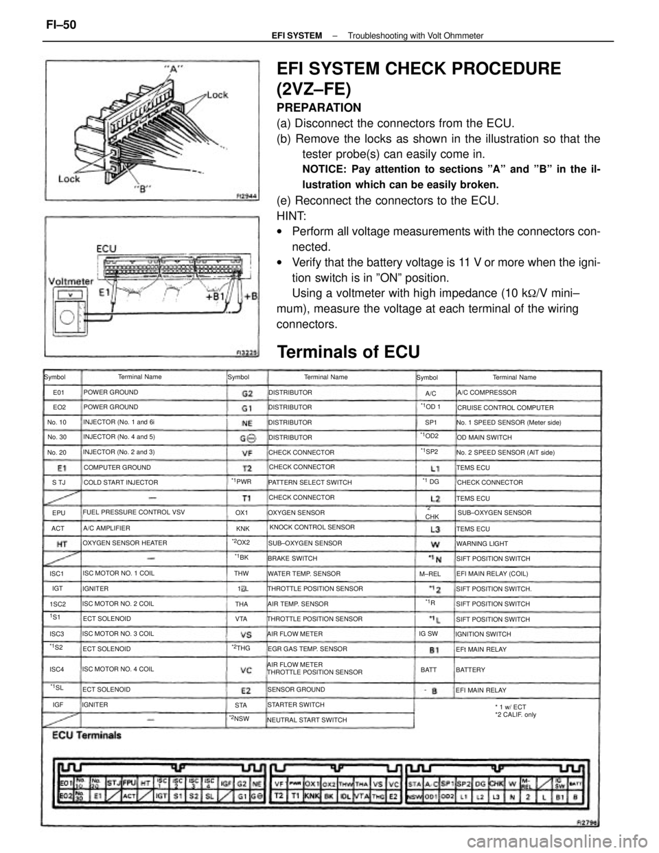
EFI SYSTEM CHECK PROCEDURE
(2VZ±FE)
PREPARATION
(a) Disconnect the connectors from the ECU.
(b) Remove the locks as shown in the illustration so that the
tester probe(s) can easily come in.
NOTICE: Pay attention to sections ºAº and ºBº in the il-
lustration which can be easily broken.
(e) Reconnect the connectors to the ECU.
HINT:
wPerform all voltage measurements with the connectors con-
nected.
wVerify that the battery voltage is 11 V or more when the igni-
tion switch is in ºONº position.
Using a voltmeter with high impedance (10 k
�/V mini±
mum), measure the voltage at each terminal of the wiring
connectors.
AIR FLOW METER
THROTTLE POSITION SENSOR
Terminals of ECU
No. 1 SPEED SENSOR (Meter side)
No. 2 SPEED SENSOR (AlT side)
THROTTLE POSITION SENSOR FUEL PRESSURE CONTROL VSV
THROTTLE POSITION SENSORCRUISE CONTROL COMPUTER
* 1 w/ ECT
*2 CALIF. only KNOCK CONTROL SENSOR PATTERN SELECT SWITCH
OXYGEN SENSOR HEATER
NEUTRAL START SWITCHEGR GAS TEMP. SENSOR INJECTOR (No. 2 and 3)INJECTOR (No. 4 and 5)
SIFT POSITION SWITCH.
ISC MOTOR NO. 3 COILINJECTOR (No. 1 and 6i
ISC MOTOR NO. 1 COIL
ISC MOTOR NO. 4 COILSIFT POSITION SWITCH ISC MOTOR NO. 2 COILWATER TEMP. SENSORSUB±OXYGEN SENSOR
SIFT POSITION SWITCH COLD START INJECTOR
EFI MAIN RELAY (COIL)
SIFT POSITION SWITCHSUB±OXYGEN SENSOR CHECK CONNECTOR
COMPUTER GROUND
CHECK CONNECTORCHECK CONNECTOR CHECK CONNECTOR
AIR TEMP. SENSORA/C COMPRESSOR
SENSOR GROUNDTerminal Name
OXYGEN SENSOROD MAIN SWITCH
STARTER SWITCHIGNITION SWITCH Terminal Name
AIR FLOW METERTerminal Name
POWER GROUND
POWER GROUND
WARNING LIGHT
EFI MAIN RELAY BRAKE SWITCH
EFt MAIN RELAY ECT SOLENOID
ECT SOLENOIDA/C AMPLIFIER
ECT SOLENOIDDISTRIBUTOR
DISTRIBUTOR DISTRIBUTOR
DISTRIBUTOR
TEMS ECU
TEMS ECU
TEMS ECU Symbol Symbol Symbol
BATTERY IGNITER
IGNITER
*2NSW
*1OD2
No. 30 No. 10
No. 20
*1PWR
*2OX2
M±REL
*1OD 1
*2CHK
*2THGIG SW
*1SP2
BATT
*1SL
*1 DG
1S1THW
*1S2
*1BK
ISC4 1SC2 ISC1
ISC3VTAOX1
ACTS TJSP1
THA
STAKNK EO2 E01
IGT
*1R A/C
EPU
1
L
IGF
± EFI SYSTEMTroubleshooting with Volt OhmmeterFI±50
Page 1082 of 2389
There is no voltage between ECU terminal No. 10, No. 20
and/or No. 30 and E41 and/or E02. (IG SW ON)
Check that there is voltage between ECU terminal No. 10,
No. 20 or No. 30 and body ground.
Check wiring between ECU terminal E01 and/or
E02 and body ground.
Check resistance of magnetic coil in each injector.
STD resistance: Approx. 13.8�
Check wiring between ECU
terminal No. 10, No. 20 and/or
No. 30 and battery.Check fusible link and
ignition switch.Repair or replace.
Try another ECU.
Repair or replace. Repair or replace.
Replace injector.STD voltage
No voltage
IG SW ON
Terminals
Condition Trouble
No.
BADBAD
BAD
BAD
± EFI SYSTEMTroubleshooting with Volt OhmmeterFI±58
Page 1183 of 2389
No fuel supply to injector
wNo fuel in tank
wFuel pump no working
wFuel filter clogged
wFuel line clogged or leaking
EFI system problems
Ignition problems
wIgnition coil
wIgniter
wDistributor
Spark plug faulty
High±tension cord disconnected or broken
Vacuum leaks
wPCV line
wEGR line
wIntake manifold
wAir intake chamber
wThrottle body
wISC valve
wBrake booster tine
Pulling in air between air flow meter and
throttle body
Low compression
Spark plug faulty
High±tension cord faulty
Ignition problems
wIgnition coil
wIgniter
wDistributor
Incorrect ignition timing
Vacuum leaks
wPCV line
wEGR line
wIntake manifold
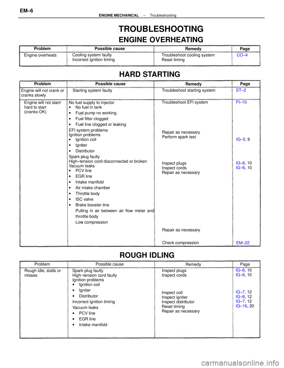
TROUBLESHOOTING
ENGINE OVERHEATING
Inspect coil
Inspect igniter
Inspect distributor
Reset timing
Repair as necessaryInspect plugs
Inspect cords
Repair as necessary Troubleshoot cooling system
Reset timing
Engine will not start/
hard to start
(cranks OK)Cooling system faulty
Incorrect ignition timing
Repair as necessary
Perform spark test Engine will not crank or
cranks slowly
IG±7, 12
IG±8, 12
IG±7, 12
IG±16, 20 Rough idle, stalls or
misses
HARD STARTING
Troubleshoot starting system
Inspect plugs
Inspect cords Troubleshoot EFI system
ROUGH IDLING
Starting system faulty
Check compression Repair as necessary Engine overheats
IG±6, 10
IG±6, 10 IG±6, 10
IG±6, 10 Possible cause
Possible cause Possible cause
Remedy Remedy
Problem
Remedy Problem Problem
IG±5, 9
EM±22Page
Page
Page CO±4
FI±10 ST±2
± ENGINE MECHANICALTroubleshootingEM±6
Page 1185 of 2389
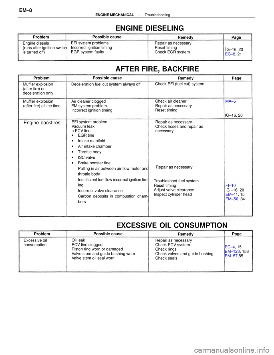
EFI system problem
Vacuum leak
a PCV line
wEGR tine
wIntake manifold
wAir intake chamber
wThrottle body
wISC valve
wBrake booster fine
Pulling in air between air flow meter and
throttle body
Insufficient fuel flow incorrect ignition tim-
ing
Incorrect valve clearance
Carbon deposits in combustion cham-
bers
Oil leak
PCV line clogged
Piston ring worn or damaged
Valve stem and guide bushing worn
Valve stem oil seal wornRepair as necessary
Check PCV system
Check rings
Check valves and guide bushing
Check seals Troubleshoot fuel system
Reset timing
Adjust valve clearance
Inspect cylinder headRepair as necessary
Check hoses and repair as
necessary Air cleaner clogged
EM system problem
Incorrect ignition timing EFI system problems
Incorrect ignition timing
EGR system faulty
Deceleration fuel cut system always off
Check air cleaner
Repair as necessary
Reset timing Repair as necessary
Reset timing
Check EGR system
EXCESSIVE OIL CONSUMPTION
Engine diesels
(runs after ignition switch
is turned off)
Muffler explosion
(after fire) on
deceleration only
FI±10
IG ±16, 20
EM±11, 15
EM±56, 84 Muffler explosion
(after fire) all the time
AFTER FIRE, BACKFIRE
EC±4, 15
EM±123, 156
EM±57,85
ENGINE DIESELING
Check EFI (fuel cut) system
Excessive oil
consumptionRepair as necessary
IG±16, 20
EC±8, 21
Engine backfires
Possible cause Possible cause
Possible causelG±16, 20 Problem
Problem
RemedyRemedy
ProblemRemedy
Page Page
MA±5Page
± ENGINE MECHANICALTroubleshootingEM±8
Page 1199 of 2389
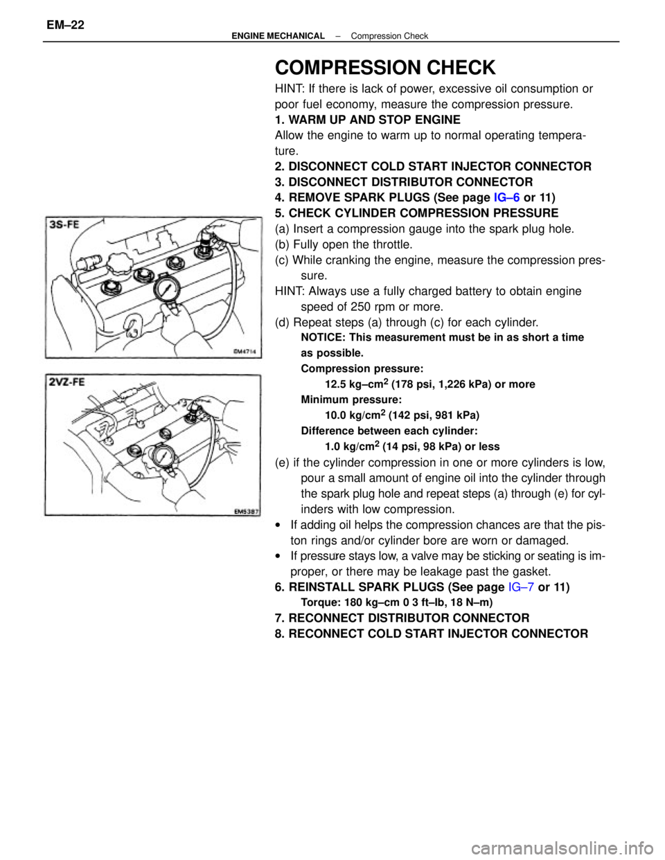
COMPRESSION CHECK
HINT: If there is lack of power, excessive oil consumption or
poor fuel economy, measure the compression pressure.
1. WARM UP AND STOP ENGINE
Allow the engine to warm up to normal operating tempera-
ture.
2. DISCONNECT COLD START INJECTOR CONNECTOR
3. DISCONNECT DISTRIBUTOR CONNECTOR
4. REMOVE SPARK PLUGS (See page IG±6 or 11)
5. CHECK CYLINDER COMPRESSION PRESSURE
(a) Insert a compression gauge into the spark plug hole.
(b) Fully open the throttle.
(c) While cranking the engine, measure the compression pres-
sure.
HINT: Always use a fully charged battery to obtain engine
speed of 250 rpm or more.
(d) Repeat steps (a) through (c) for each cylinder.
NOTICE: This measurement must be in as short a time
as possible.
Compression pressure:
12.5 kg±cm
2 (178 psi, 1,226 kPa) or more
Minimum pressure:
10.0 kg/cm
2 (142 psi, 981 kPa)
Difference between each cylinder:
1.0 kg/cm
2 (14 psi, 98 kPa) or less
(e) if the cylinder compression in one or more cylinders is low,
pour a small amount of engine oil into the cylinder through
the spark plug hole and repeat steps (a) through (e) for cyl-
inders with low compression.
wIf adding oil helps the compression chances are that the pis-
ton rings and/or cylinder bore are worn or damaged.
wIf pressure stays low, a valve may be sticking or seating is im-
proper, or there may be leakage past the gasket.
6. REINSTALL SPARK PLUGS (See page IG±7 or 11)
Torque: 180 kg±cm 0 3 ft±Ib, 18 N±m)
7. RECONNECT DISTRIBUTOR CONNECTOR
8. RECONNECT COLD START INJECTOR CONNECTOR
± ENGINE MECHANICALCompression CheckEM±22