Page 1151 of 2389
Resistance of ECU Wiring Connectors (2VZ±FE)
Coolant temp. 80°C (176°F)
Measuring plate fully closed
Intake air temp. 20°C (68°F)
Measuring plate fully open
Throttle valve fully closed
Throttle valve fully closed Throttle valve fully openSTD resistance (
��
Throttle valve open TerminalsCondition
± EFI SYSTEMElectronic Control System (Electronic Controlled Unit(ECU))
FI±136
Page 1198 of 2389
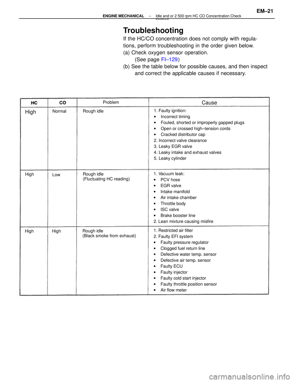
Troubleshooting
If the HC/CO concentration does not comply with regula-
tions, perform troubleshooting in the order given below.
(a) Check oxygen sensor operation.
(See page FI±129)
(b) See the table below for possible causes, and then inspect
and correct the applicable causes if necessary.
1. Faulty ignition:
wIncorrect timing
wFouled, shorted or improperly gapped plugs
wOpen or crossed high±tension cords
wCracked distributor cap
2. Incorrect valve clearance
3. Leaky EGR valve
4. Leaky intake and exhaust valves
5. Leaky cylinder
1. Restricted air filter
2. Faulty EFI system
wFaulty pressure regulator
wClogged fuel return line
wDefective water temp. sensor
wDefective air temp. sensor
wFaulty ECU
wFaulty injector
wFaulty cold start injector
wFaulty throttle position sensor
wAir flow meter 1. Vacuum leak:
wPCV hose
wEGR valve
wIntake manifold
wAir intake chamber
wThrottle body
wISC valve
wBrake booster line
2. Lean mixture causing misfire
Rough idle
(Black smoke from exhaust)Rough idle
(Fluctuating HC reading) Rough idleProblem
Normal
Cause
High
High
HighHigh
Low
± ENGINE MECHANICALIdle and or 2 500 rpm HC CO Concentration CheckMethod
EM±21
Page 1226 of 2389
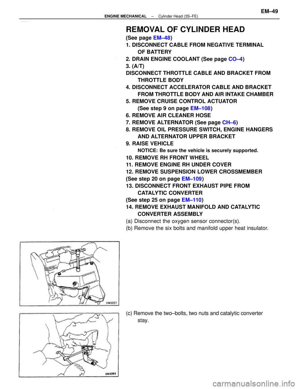
REMOVAL OF CYLINDER HEAD
(See page EM±48)
1. DISCONNECT CABLE FROM NEGATIVE TERMINAL
OF BATTERY
2. DRAIN ENGINE COOLANT (See page CO±4)
3. (A/T)
DISCONNECT THROTTLE CABLE AND BRACKET FROM
THROTTLE BODY
4. DISCONNECT ACCELERATOR CABLE AND BRACKET
FROM THROTTLE BODY AND AIR INTAKE CHAMBER
5. REMOVE CRUISE CONTROL ACTUATOR
(See step 9 on page EM±108)
6. REMOVE AIR CLEANER HOSE
7. REMOVE ALTERNATOR (See page CH±6)
8. REMOVE OIL PRESSURE SWITCH, ENGINE HANGERS
AND ALTERNATOR UPPER BRACKET
9. RAISE VEHICLE
NOTICE: Be sure the vehicle is securely supported.
10. REMOVE RH FRONT WHEEL
11. REMOVE ENGINE RH UNDER COVER
12. REMOVE SUSPENSION LOWER CROSSMEMBER
(See step 20 on page EM±109)
13. DISCONNECT FRONT EXHAUST PIPE FROM
CATALYTIC CONVERTER
(See step 25 on page EM±110)
14. REMOVE EXHAUST MANIFOLD AND CATALYTIC
CONVERTER ASSEMBLY
(a) Disconnect the oxygen sensor connector(s).
(b) Remove the six bolts and manifold upper heat insulator.
(c) Remove the two±bolts, two nuts and catalytic converter
stay.
± ENGINE MECHANICALCylinder Head (3S±FE)EM±49
Page 1230 of 2389
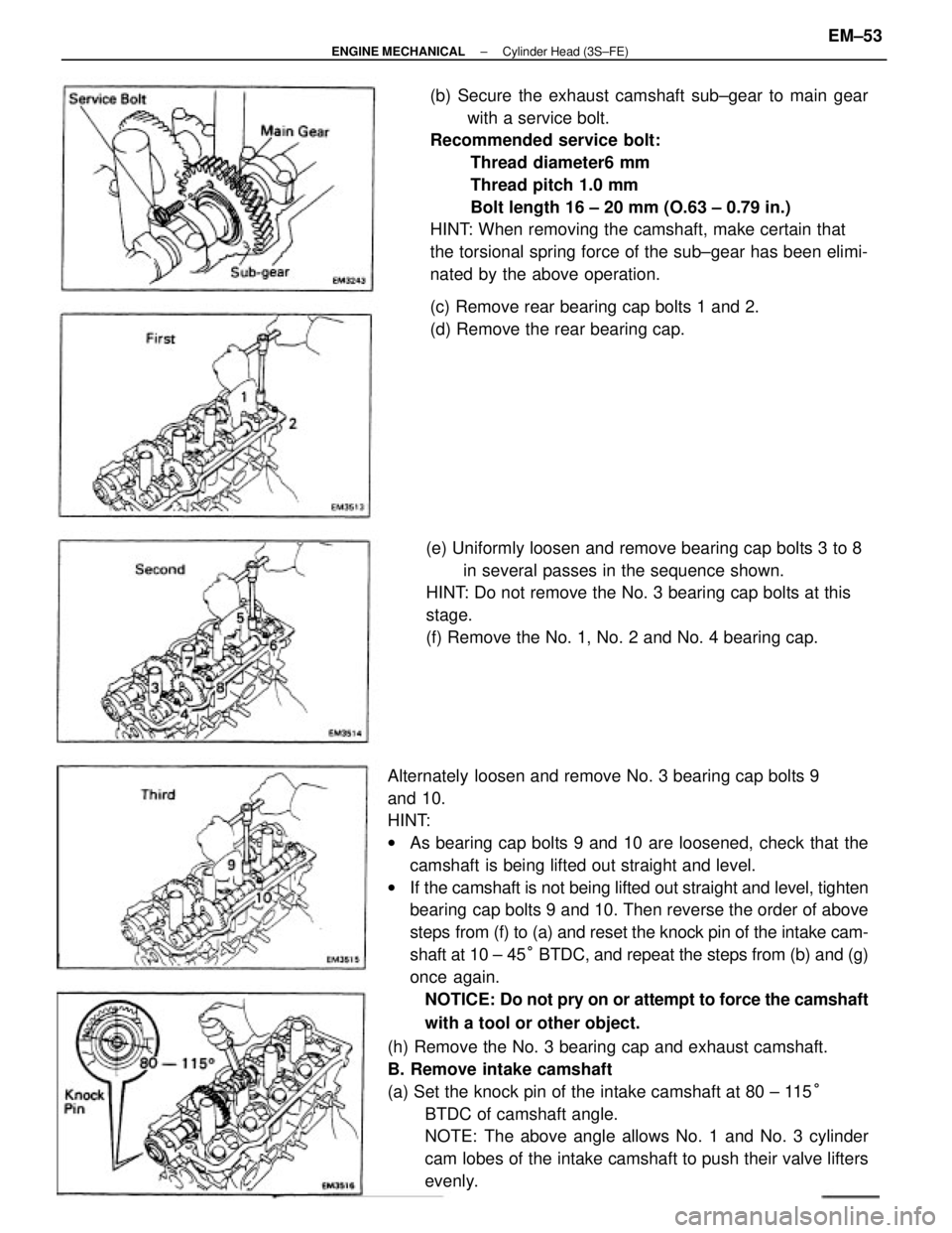
Alternately loosen and remove No. 3 bearing cap bolts 9
and 10.
HINT:
wAs bearing cap bolts 9 and 10 are loosened, check that the
camshaft is being lifted out straight and level.
wIf the camshaft is not being lifted out straight and level, tighten
bearing cap bolts 9 and 10. Then reverse the order of above
steps from (f) to (a) and reset the knock pin of the intake cam-
shaft at 10 ± 45° BTDC, and repeat the steps from (b) and (g)
once again.
NOTICE: Do not pry on or attempt to force the camshaft
with a tool or other object.
(h) Remove the No. 3 bearing cap and exhaust camshaft.
B. Remove intake camshaft
(a) Set the knock pin of the intake camshaft at 80 ± 115°
BTDC of camshaft angle.
NOTE: The above angle allows No. 1 and No. 3 cylinder
cam lobes of the intake camshaft to push their valve lifters
evenly.(b) Secure the exhaust camshaft sub±gear to main gear
with a service bolt.
Recommended service bolt:
Thread diameter6 mm
Thread pitch 1.0 mm
Bolt length 16 ± 20 mm (O.63 ± 0.79 in.)
HINT: When removing the camshaft, make certain that
the torsional spring force of the sub±gear has been elimi-
nated by the above operation.
(e) Uniformly loosen and remove bearing cap bolts 3 to 8
in several passes in the sequence shown.
HINT: Do not remove the No. 3 bearing cap bolts at this
stage.
(f) Remove the No. 1, No. 2 and No. 4 bearing cap.(c) Remove rear bearing cap bolts 1 and 2.
(d) Remove the rear bearing cap.
± ENGINE MECHANICALCylinder Head (3S±FE)EM±53
Page 1253 of 2389
REMOVAL OF CYLINDER HEADS
(See page EM±75)
1. DISCONNECT CABLE FROM NEGATIVE TERMINAL
OF BATTERY
2. DRAIN ENGINE COOLANT (See page CO±5)
3. (A/T)
DISCONNECT THROTTLE CABLE FROM THROTTLE
BODY
4. DISCONNECT ACCELERATOR CABLE FROM
THROTTLE BODY
5. (w/ CRUISE CONTROL SYSTEM)
REMOVE CRUISE CONTROL ACTUATOR AND
VACUUM PUMP (See step 74 on page EM±140)
6. REMOVE AIR CLEANER HOSE
(a) Disconnect the following hoses:
(1) RSC valve air hose
(2) Vacuum pipe hose
(b) Remove the air cleaner hose.
7. RAISE VEHICLE
NOTICE: Be sure the vehicle is securely supported.
8. REMOVE ENGINE RH UNDER COVER
9. REMOVE SUSPENSION LOWER CROSSMEMBER
(See step 26 on page EM±142)
10. REMOVE FRONT EXHAUST PIPE
(See step 27 on page EM±142)
11. REMOVE ALTERNATOR (See page CH±7)
12. REMOVE ISC VALVE
(See steps 2 to 4 on pages Fl±118 and 119)
13. REMOVE THROTTLE BODY
(See steps 5 to 6 on page FI±113)
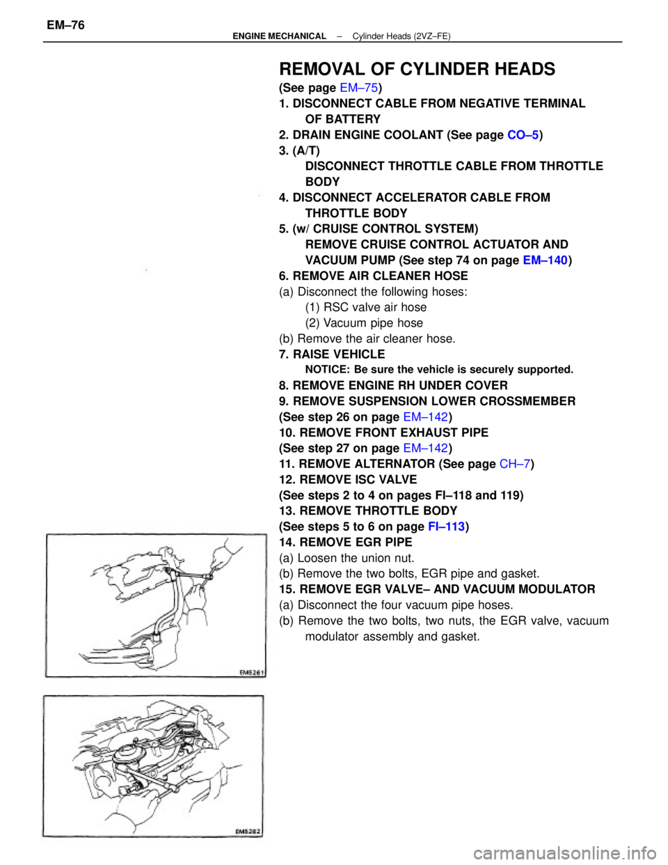
14. REMOVE EGR PIPE
(a) Loosen the union nut.
(b) Remove the two bolts, EGR pipe and gasket.
15. REMOVE EGR VALVE± AND VACUUM MODULATOR
(a) Disconnect the four vacuum pipe hoses.
(b) Remove the two bolts, two nuts, the EGR valve, vacuum
modulator assembly and gasket.
± ENGINE MECHANICALCylinder Heads (2VZ±FE)EM±76
Page 1257 of 2389
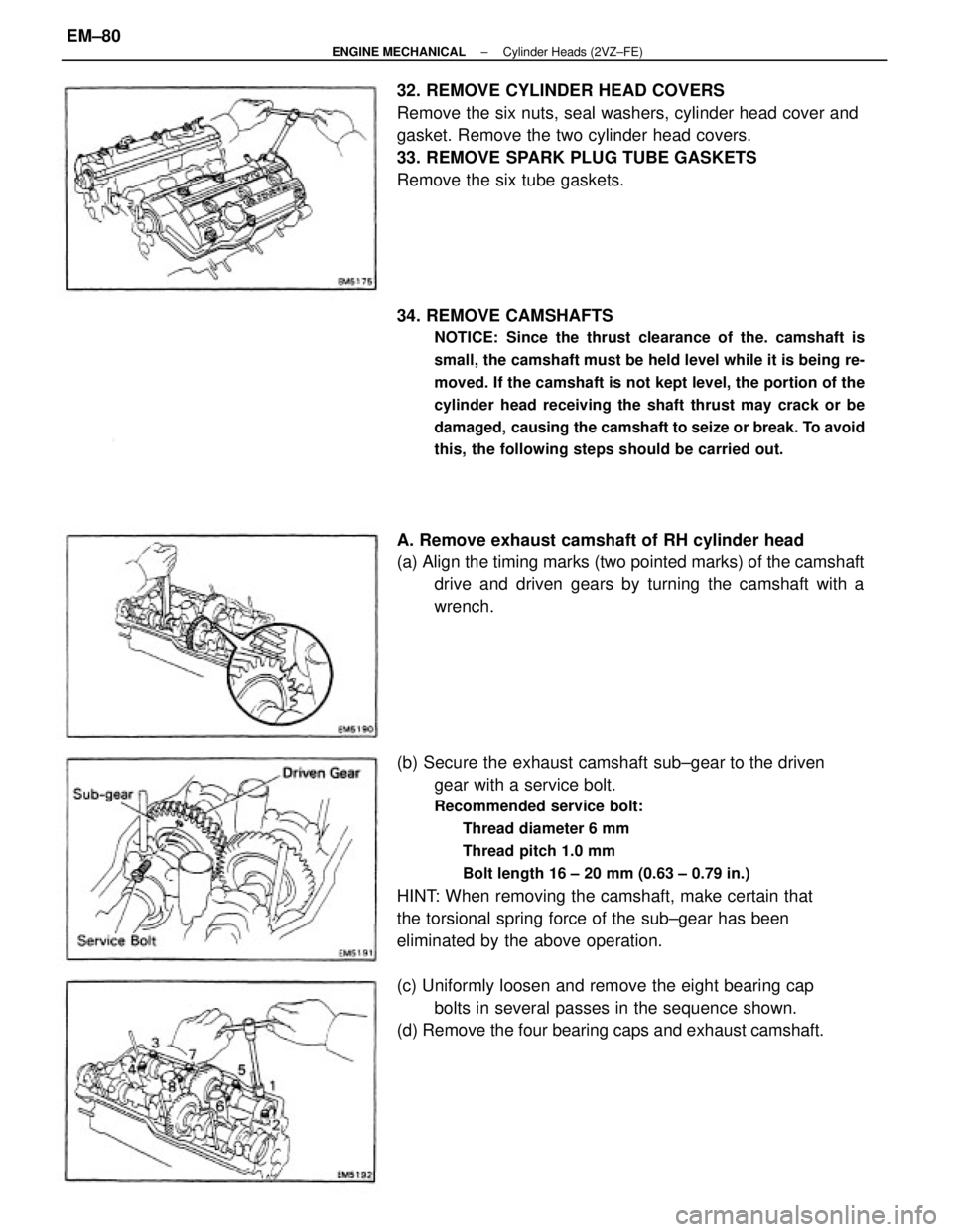
(b) Secure the exhaust camshaft sub±gear to the driven
gear with a service bolt.
Recommended service bolt:
Thread diameter 6 mm
Thread pitch 1.0 mm
Bolt length 16 ± 20 mm (0.63 ± 0.79 in.)
HINT: When removing the camshaft, make certain that
the torsional spring force of the sub±gear has been
eliminated by the above operation. 32. REMOVE CYLINDER HEAD COVERS
Remove the six nuts, seal washers, cylinder head cover and
gasket. Remove the two cylinder head covers.
33. REMOVE SPARK PLUG TUBE GASKETS
Remove the six tube gaskets.
34. REMOVE CAMSHAFTS
NOTICE: Since the thrust clearance of the. camshaft is
small, the camshaft must be held level while it is being re-
moved. If the camshaft is not kept level, the portion of the
cylinder head receiving the shaft thrust may crack or be
damaged, causing the camshaft to seize or break. To avoid
this, the following steps should be carried out.
A. Remove exhaust camshaft of RH cylinder head
(a) Align the timing marks (two pointed marks) of the camshaft
drive and driven gears by turning the camshaft with a
wrench.
(c) Uniformly loosen and remove the eight bearing cap
bolts in several passes in the sequence shown.
(d) Remove the four bearing caps and exhaust camshaft.
± ENGINE MECHANICALCylinder Heads (2VZ±FE)EM±80
Page 1258 of 2389
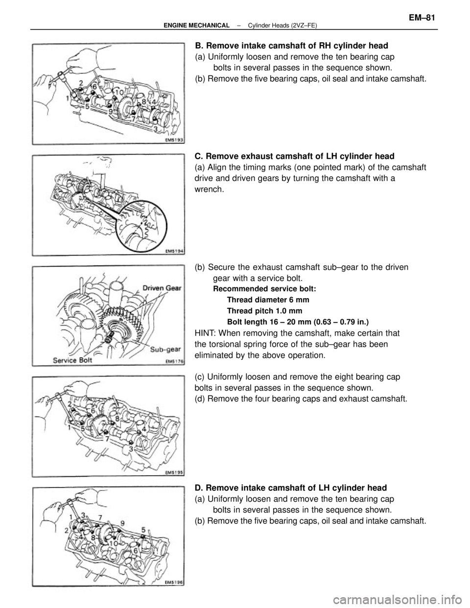
(b) Secure the exhaust camshaft sub±gear to the driven
gear with a service bolt.
Recommended service bolt:
Thread diameter 6 mm
Thread pitch 1.0 mm
Bolt length 16 ± 20 mm (0.63 ± 0.79 in.)
HINT: When removing the camshaft, make certain that
the torsional spring force of the sub±gear has been
eliminated by the above operation.
D. Remove intake camshaft of LH cylinder head
(a) Uniformly loosen and remove the ten bearing cap
bolts in several passes in the sequence shown.
(b) Remove the five bearing caps, oil seal and intake camshaft.B. Remove intake camshaft of RH cylinder head
(a) Uniformly loosen and remove the ten bearing cap
bolts in several passes in the sequence shown.
(b) Remove the five bearing caps, oil seal and intake camshaft.
C. Remove exhaust camshaft of LH cylinder head
(a) Align the timing marks (one pointed mark) of the camshaft
drive and driven gears by turning the camshaft with a
wrench.
(c) Uniformly loosen and remove the eight bearing cap
bolts in several passes in the sequence shown.
(d) Remove the four bearing caps and exhaust camshaft.
± ENGINE MECHANICALCylinder Heads (2VZ±FE)EM±81
Page 1286 of 2389
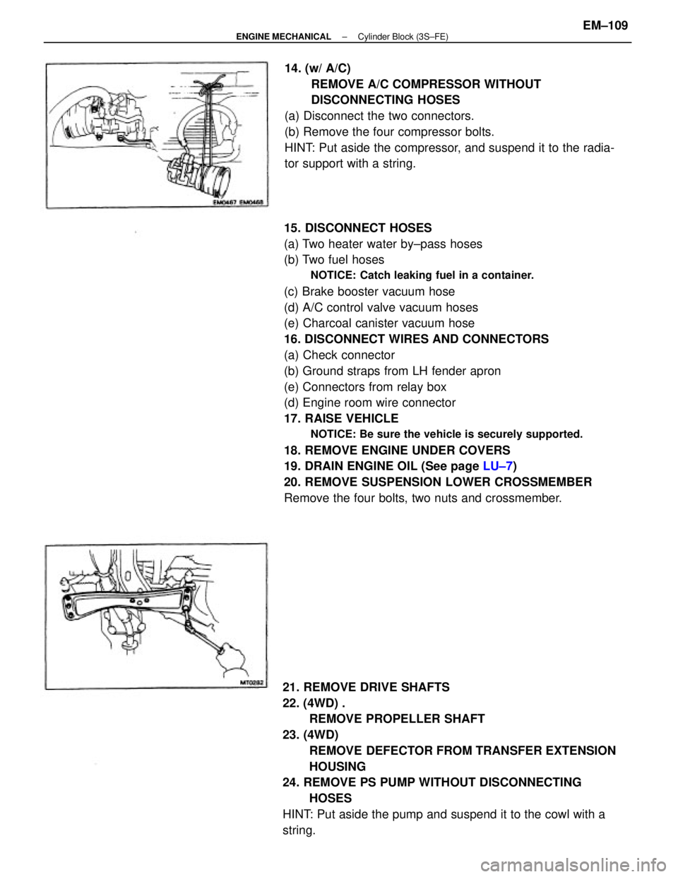
15. DISCONNECT HOSES
(a) Two heater water by±pass hoses
(b) Two fuel hoses
NOTICE: Catch leaking fuel in a container.
(c) Brake booster vacuum hose
(d) A/C control valve vacuum hoses
(e) Charcoal canister vacuum hose
16. DISCONNECT WIRES AND CONNECTORS
(a) Check connector
(b) Ground straps from LH fender apron
(e) Connectors from relay box
(d) Engine room wire connector
17. RAISE VEHICLE
NOTICE: Be sure the vehicle is securely supported.
18. REMOVE ENGINE UNDER COVERS
19. DRAIN ENGINE OIL (See page LU±7)
20. REMOVE SUSPENSION LOWER CROSSMEMBER
Remove the four bolts, two nuts and crossmember.
21. REMOVE DRIVE SHAFTS
22. (4WD) .
REMOVE PROPELLER SHAFT
23. (4WD)
REMOVE DEFECTOR FROM TRANSFER EXTENSION
HOUSING
24. REMOVE PS PUMP WITHOUT DISCONNECTING
HOSES
HINT: Put aside the pump and suspend it to the cowl with a
string.14. (w/ A/C)
REMOVE A/C COMPRESSOR WITHOUT
DISCONNECTING HOSES
(a) Disconnect the two connectors.
(b) Remove the four compressor bolts.
HINT: Put aside the compressor, and suspend it to the radia-
tor support with a string.
± ENGINE MECHANICALCylinder Block (3S±FE)EM±109