Page 1287 of 2389

26. REMOVE ENGINE MOUNTING CENTER MEMBER
(2WD)
Remove the eight bolts, two nuts and center member.
(4WD )
Remove the eight bolts, two nuts and center member.
27. REMOVE ENGINE FRONT MOUNTING INSULATOR
AND BRACKET
28. (2WD)
REMOVE ENGINE CENTER MOUNTING INSULATOR
AND BRACKET ASSEMBLY
29. REMOVE ENGINE REAR MOUNTING INSULATOR
AND BRACKET
30. LOWER VEHICLE
31. DISCONNECT ENGINE WIRE
(a) Remove the glove compartment box.
(b) Disconnect the following connectors:
(1) Three TCCS ECU connectors
(2) Circuit opening relay connector
(3) Cowl wire connector
(4) Instrument panel wire connector
(c) Pull out the engine wire from the cowl panel.
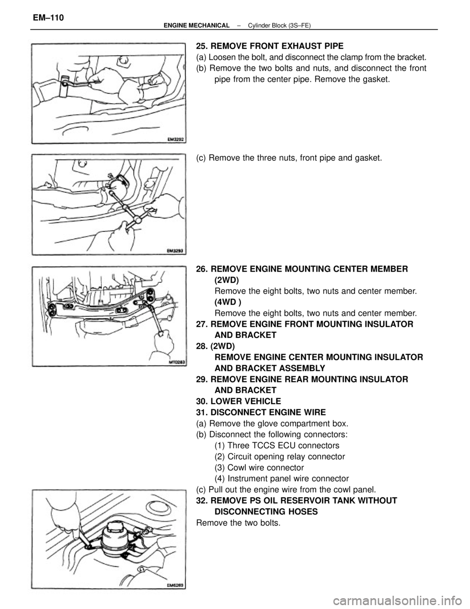
32. REMOVE PS OIL RESERVOIR TANK WITHOUT
DISCONNECTING HOSES
Remove the two bolts. 25. REMOVE FRONT EXHAUST PIPE
(a) Loosen the bolt, and disconnect the clamp from the bracket.
(b) Remove the two bolts and nuts, and disconnect the front
pipe from the center pipe. Remove the gasket.
(c) Remove the three nuts, front pipe and gasket.
± ENGINE MECHANICALCylinder Block (3S±FE)EM±110
Page 1311 of 2389

5. INSTALL PS OIL RESERVOIR TANK
Install the two bolts.
6. CONNECT ENGINE WIRE
(a) Push in the engine wire through the cowl panel.
(b) Connect the following connectors.
(1) Three TCCS ECU connectors
(2) Circuit opening relay connector
(3) Cowl wire connector
(4) Instrument panel wire connector
(c) Install the glove compartment box.
7. RAISE VEHICLE
NOTICE: Be sure vehicle is securely supported.
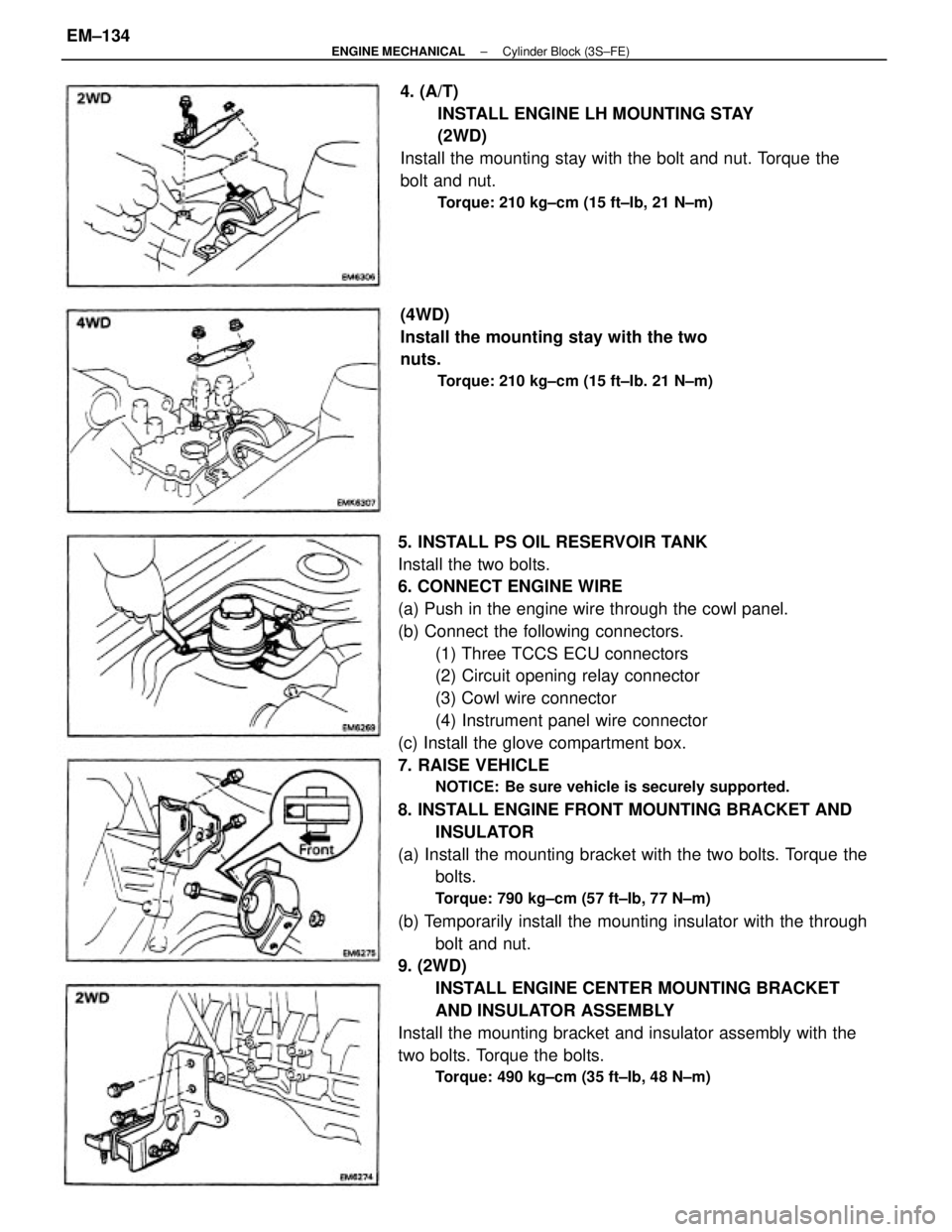
8. INSTALL ENGINE FRONT MOUNTING BRACKET AND
INSULATOR
(a) Install the mounting bracket with the two bolts. Torque the
bolts.
Torque: 790 kg±cm (57 ft±Ib, 77 N±m)
(b) Temporarily install the mounting insulator with the through
bolt and nut.
9. (2WD)
INSTALL ENGINE CENTER MOUNTING BRACKET
AND INSULATOR ASSEMBLY
Install the mounting bracket and insulator assembly with the
two bolts. Torque the bolts.
Torque: 490 kg±cm (35 ft±Ib, 48 N±m)
4. (A/T)
INSTALL ENGINE LH MOUNTING STAY
(2WD)
Install the mounting stay with the bolt and nut. Torque the
bolt and nut.
Torque: 210 kg±cm (15 ft±Ib, 21 N±m)
(4WD)
Install the mounting stay with the two
nuts.
Torque: 210 kg±cm (15 ft±Ib. 21 N±m)
± ENGINE MECHANICALCylinder Block (3S±FE)EM±134
Page 1319 of 2389

25. DISCONNECT ENGINE WIRE FROM CABIN
(a) Remove the under cover.
(b) Remove the glove compartment box.
(c) Disconnect the following connectors:
(1) Three engine & ECT ECU connectors
(2) Circuit opening relay connector
(3) Cowl wire connector
(4) Instrument panel wire connector
(d) Pull out the engine wire from the cowl panel.
26. REMOVE SUSPENSION LOWER CROSSMEMBER
Remove the two bolts, two nuts and crossmember.
28. REMOVE A/C COMPRESSOR WITHOUT
DISCONNECTING HOSES
(a) Disconnect the two connectors.
(b) Remove the four compressor bolts.
HINT: Put aside the compressor, and suspend it to the radia-
tor support with a string.22. (M /T)
REMOVE CLUTCH RELEASE CYLINDER AND TUBE
CLAMP WITHOUT DISCONNECTING TUBE
23. DISCONNECT SPEEDOMETER CABLE
24. DISCONNECT TRANSAXLE CONTROL CABLE(S)
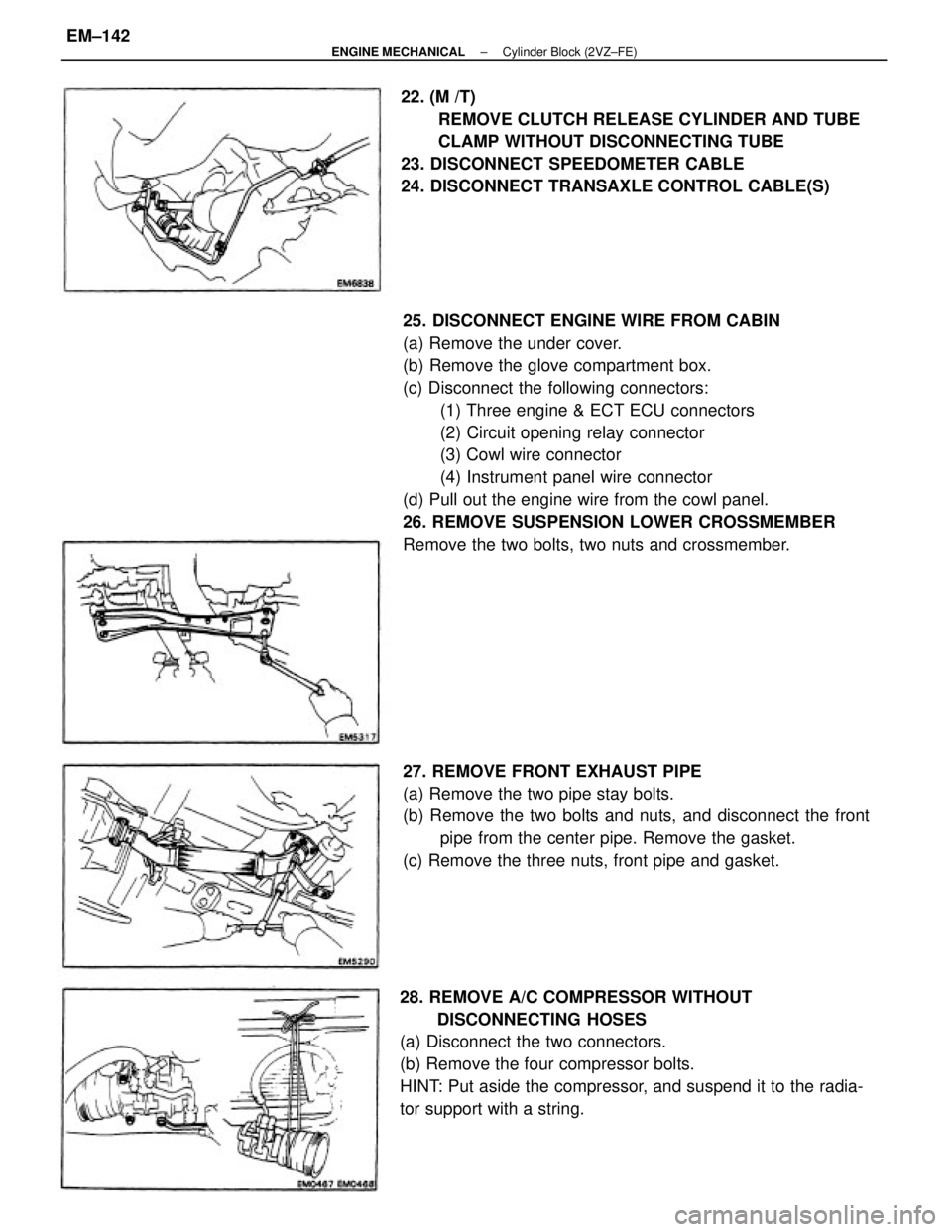
27. REMOVE FRONT EXHAUST PIPE
(a) Remove the two pipe stay bolts.
(b) Remove the two bolts and nuts, and disconnect the front
pipe from the center pipe. Remove the gasket.
(c) Remove the three nuts, front pipe and gasket.
± ENGINE MECHANICALCylinder Block (2VZ±FE)EM±142
Page 1349 of 2389

16. CONNECT ENGINE WIRE TO CABIN
(a) Push in the engine wire through the cowl panel.
(b) Connect the following connectors.
(1) Three TCCS ECU connectors
(2) Circuit opening relay connector
(3) Cowl wire connector
(4) Instrument panel wire connector
(c) Install the glove compartment box.
(d) Install the under cover.
17. CONNECT TRANSAXLE CONTROL CABLE(S)
18. CONNECT SPEEDOMETER CABLE
19. (M /T)
INSTALL CLUTCH RELEASE CYLINDER AND TUBE
CLAMP
20. (M /T)
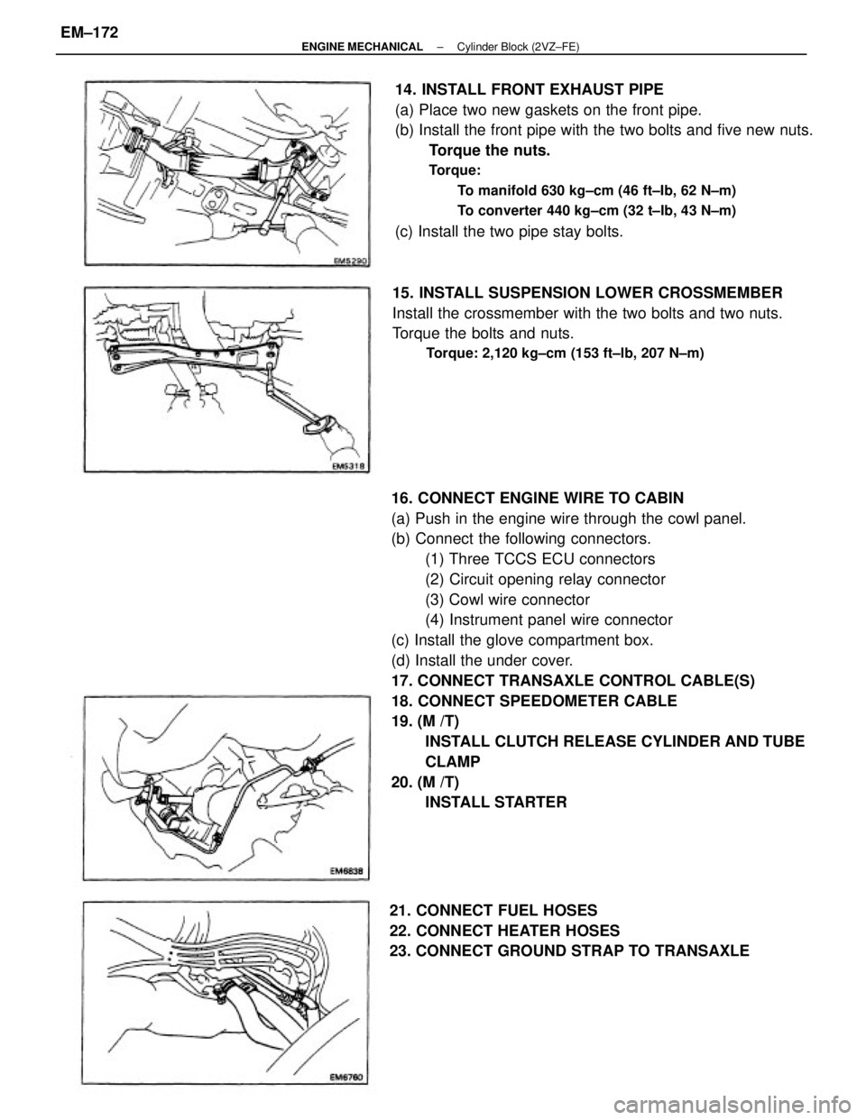
INSTALL STARTER 14. INSTALL FRONT EXHAUST PIPE
(a) Place two new gaskets on the front pipe.
(b) Install the front pipe with the two bolts and five new nuts.
Torque the nuts.
Torque:
To manifold 630 kg±cm (46 ft±Ib, 62 N±m)
To converter 440 kg±cm (32 t±Ib, 43 N±m)
(c) Install the two pipe stay bolts.
15. INSTALL SUSPENSION LOWER CROSSMEMBER
Install the crossmember with the two bolts and two nuts.
Torque the bolts and nuts.
Torque: 2,120 kg±cm (153 ft±lb, 207 N±m)
21. CONNECT FUEL HOSES
22. CONNECT HEATER HOSES
23. CONNECT GROUND STRAP TO TRANSAXLE
± ENGINE MECHANICALCylinder Block (2VZ±FE)EM±172
Page 1370 of 2389
2. CONNECT STEERING KNUCKLE TO SHOCK
ABSORBER
NOTICE: Apply engine oil to the threads of the two bolts.
(a) Connect the steering knuckle to the shock absorber
lower bracket.
(b) Insert the bolts and align the matchmarks of the camber
adjusting cam.
(c) Torque the nuts.
Torque: 3,100 kg±cm (224 ft±Ib, 304 N±m)
3. CONNECT TIE ROD END TO STEERING KNUCKLE
Torque the castle nut and secure it with a new cotter pin.
Torque: 500 kg±cm (36 ft±Ib, 49 N±m)
INSTALLATION OF FRONT AXLE HUB
(See page FA ± 7)
1. INSTALL STEERING KNUCKLE TO LOWER
SUSPENSION ARM
install the steering knuckle to the lower suspension arm,
and temporarily install the nut.
4. TORQUE BALL JOINT TO LOWER ARM
Install and torque the castle nut and secure it with a new
cotter pin.
Torque: 1,250 kg±cm (90 ft±lb, 123 N±m)
5. INSTALL ROTOR DISC TO AXLE HUB
6. INSTALL DISC BRAKE CALIPER TO STEERING
KNUCKLE
Torque: 1,190 kg±cm (86 ft±Ib, 117 N±m)
± FRONT AXLE AND SUSPENSIONFront Axle HubFA±13
Page 1371 of 2389
7. INSTALL BEARING LOCK NUT, LOCK NUT CAP AND
COTTER PIN
(a) Torque the bearing lock nut while depressing the brake
pedal.
Torque: 1,900 kg±cm (137 ft±lb , 186 N±m)
(b) Install the lock nut cap, and secure it with a new cotter
pin.
8. CHECK FRONT WHEEL ALIGNMENT
(See page FA ± 3)
REPLACEMENT OF FRONT AXLE HUB BOLT
1. MOVE DISC BRAKE CALIPER
Remove the disc brake caliper from the steering knuckle and
suspended it with wire.
2. REMOVE ROTOR DISC
3. REMOVE FRONT AXLE HUB BOLT
(a) Align the disc brake dust cover cutting portion and axle
hub bolt.
(b) Using SST, remove the axle hub bolt.
SST 09650±17011
6. INSTALL DISC BRAKE CALIPER TO STEERING
KNUCKLE
Torque: 1,190kg±cm (86 ft±lb , 117 N±m)
4. INSTALL FRONT AXLE HUB BOLT
(a) Hold the front axle hub, and install a new hub
bolt.
5. INSTALL ROTOR DISC
± FRONT AXLE AND SUSPENSIONFront Axle HubFA±14
Page 1381 of 2389
7±2. (GKN TYPE)
ASSEMBLE BOOT CLAMPS TO BOTH BOOT
(a) Be sure the boot (large side) is on shaft groove.
(b) Using a boot clamp tool, place pincer jaws in closing
hooks of large clamp.
(c) Secure clamp by drawing closing hooks together. (c) Insure that the boot is no stretched or contracted
when the drive shaft is at standard length.
Drive shaft length:
LH 558.7
+ 5.0 mm (21.996 + 0.197 in.)
R H 845.2
+ 5.0 mm (33.276 + 0.197 in.) 7.(TOYOTA TYPE)
INSTALL BOOT CLAMPS TO BOTH BOOT
(a) Be sure the boot is on the shaft groove.
(b) Bend the band and lock it as shown.
(e) Be sure the boot (small side) is on the shaft
groove.
(f) Using a boot clamp tool, tighten the clamp. (d) Check that the clamp at closed position is the
same as in the illustration.
± FRONT AXLE AND SUSPENSIONFront Drive Shaft (FWD SV21 )FA±24
Page 1384 of 2389
6. INSTALL BEARING LOCK NUT, LOCK NUT CAP AND
NEW COTTER PIN
(a) Install and torque the bearing lock nut.
Torque: 1,900 kg±cm (137 ft±Ib, 187 N±m)
(b) Install the lock nut cap and secure it with a new cotter
pin.
7. FILL TRANSAXLE WITH FLU I6
(See page MT±39)
8. INSTALL FRONT FENDER APRON SEAL
9. INSTALL ENGINE UNDER COVER
10. CHECK FRONT WHEEL ALIGNMENT
(See page FA±3)
± FRONT AXLE AND SUSPENSIONFront Drive ShaftFA±27