Page 1087 of 2389
Check that there is voltage between ECU terminal +B (+Bl)
and body ground. (IG SW ON) There is no voltage between ECU terminals ISC 1 ± ISC4
and E1 . (IG SW ON)
Check wiring between ECU terminal E1 and body ground.
Check wiring between ECU and EFI main
relay. Check ISC valve.
(See page FI±118)Refer to No. 1.
(See page FI±52)
Try another ECU. ..Replace ISC
valve.
Repair or replace.Repair or replace.STD voltage
No voltage
IG SW ON
Terminals ConditionTrouble
BADBAD
BAD No.
± EFI SYSTEMTroubleshooting with Volt OhmmeterFI±63
Page 1088 of 2389
Check that there is voltage between ECU terminal W and body
ground. There is no voltage between ECU terminals W and E1.
(Idling)
Check wiring between ECU terminal E 1 and body
ground. '
Check GAUGE fuse 7.5A and ºCHECKº
engine warning light. No trouble (ºCHECKº engine warning light off)
and engine running
Check wiring between ECU terminal
W and fuse.Fuse blows again
Repair or replace.Repair or replace.
Repair or replace.
Try another ECU.STD voltage
No voltage Terminals ConditionTrouble
NO
BAD
BAD No.
± EFI SYSTEMTroubleshooting with Volt OhmmeterFI±64
Page 1089 of 2389
Check that there is voltage between ECU terminal A/C and body
ground. There is no voltage between ECU terminals A/C and El.
(Air conditioning ON)
Check wiring between ECU terminal E 1 and body
ground.
Check that there is voltage between
amplifier terminal and body ground.
Check wiring between amplifier and
ECU or compressor.Check wiring
between ECU
terminal A/C and
amplifier. Check compressor running.Air conditioning ON
Repair or replace.Repair or replace. Try another ECU.Repair or replace.
Repair or replace.STD voltage
No voltage
IG SW ON Terminals
Condition Trouble
BAD
BAD
BADBAD
BAD No.
± EFI SYSTEMTroubleshooting with Volt OhmmeterFI±65
Page 1090 of 2389
Check that there is specified voltage between ECU terminals VF
and body ground. ¿ There is no voltage between ECU terminals VF and E 1.
Check wiring between ECU terminal E i and body ground.
Check for suction of air into exhaust system.
Check wiring between oxygen sensors and
ECU connectors. ¿¿ Check operation of oxygen sensors.Check for air leak from air intake system.
Check cold start injector.Check distributor and ignition system.
Replace oxygen sensors.* Rich malfunction only Check fuel pressure.
Check air flow meter.Check spark plugs.Repair air suction.
Repair or replace. Repair or replace_Repair or replace.
Repair or replace.
Repair or replace.Repair or replace.
Repair or replace. Try another ECU.
Check injectors.
System normal.Repair air leak.
Repair wiring. BAD
BAD
BADBADBAD BAD
BAD
BAD
BAD BADBAD
± EFI SYSTEMTroubleshooting with Volt OhmmeterFI±66
Page 1091 of 2389
Check that there is voltage between ECU terminal +B
(+B1) and body ground. (IG SW ON)No voltage between ECU terminal THG and E2.
(IG SW ON)
Check wiring between ECU terminal E1 and body ground.
Check wiring between ECU and
EGR gas temp. sensor. Check EGR gas temp. sensor.
(See page FI±126)
Replace EGR gas
temp. sensor.Refer to No. 1.
(See page FI±32)
Check EGR system.Repair or replace.
Repair or replace.
Repair or replace.
Try another ECU.
BAD
BAD
BAD BAD
± EFI SYSTEMTroubleshooting with Volt OhmmeterFI±67
Page 1102 of 2389
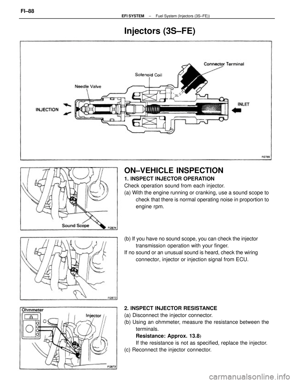
2. INSPECT INJECTOR RESISTANCE
(a) Disconnect the injector connector.
(b) Using an ohmmeter, measure the resistance between the
terminals.
Resistance: Approx. 13.8
�
If the resistance is not as specified, replace the injector.
(c) Reconnect the injector connector.
ON±VEHICLE INSPECTION
1. INSPECT INJECTOR OPERATION
Check operation sound from each injector.
(a) With the engine running or cranking, use a sound scope to
check that there is normal operating noise in proportion to
engine rpm.
(b) If you have no sound scope, you can check the injector
transmission operation with your finger.
If no sound or an unusual sound is heard, check the wiring
connector, injector or injection signal from ECU.
Injectors (3S±FE)
± EFI SYSTEMFuel System (Injectors (3S±FE))FI±88
Page 1107 of 2389
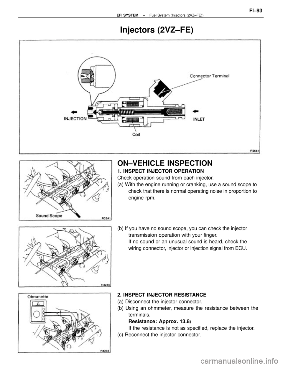
2. INSPECT INJECTOR RESISTANCE
(a) Disconnect the injector connector.
(b) Using an ohmmeter, measure the resistance between the
terminals.
Resistance: Approx. 13.8
�
If the resistance is not as specified, replace the injector.
(c) Reconnect the injector connector.
ON±VEHICLE INSPECTION
1. INSPECT INJECTOR OPERATION
Check operation sound from each injector.
(a) With the engine running or cranking, use a sound scope to
check that there is normal operating noise in proportion to
engine rpm.
(b) If you have no sound scope, you can check the injector
transmission operation with your finger.
If no sound or an unusual sound is heard, check the
wiring connector, injector or injection signal from ECU.
Injectors (2VZ±FE)
± EFI SYSTEMFuel System (Injectors (2VZ±FE))FI±93
Page 1123 of 2389
 Connect the following hoses:
wPCV hose
wWater by±pass hoses
wAir tube hose
wEmission control vacuum hoses
3. CONNECT ISC VALVE CONNECTOR
4. CONNECT THROTTLE POSITION SENSOR
CONNECTOR
5. CONNECT A")
(b) Connect the following hoses:
wPCV hose
wWater by±pass hoses
wAir tube hose
wEmission control vacuum hoses
3. CONNECT ISC VALVE CONNECTOR
4. CONNECT THROTTLE POSITION SENSOR
CONNECTOR
5. CONNECT AIR CLEANER HOSE
6. CONNECT ACCELERATOR CABLE, AND ADJUST IT
7. (A/T)
CONNECT THROTTLE CABLE, AND ADJUST IT
8. FILL WITH ENGINE COOLANT (See page CO±5)
INSTALLATION OF THROTTLE BODY
1. INSTALL ISC VALVE TO THROTTLE BODY
(See page FI±117)
2. INSTALL THROTTLE BODY
(a) Install a new gasket and the throttle body with the four bolts.
Torque: 195 kg±cm (14 ft±Ib, 19 N±m)
(b) Insert a 0.70 mm (0.028 in.) feeler gauge, between the
throttle stop screw and stop lever.
(c) Connect the test probe of an ohmmeter to the terminals
IDL and E1 of the sensor.
(d) Gradually turn the sensor clockwise until the ohmme±
ter deflects, and secure it with the two set screws.
(e) Recheck the continuity between terminals IDL and E2.
Clearance between lever
and stop screwContinuity (IDL ± El)
0.90 mm (0.035 in.) 0.50 mm (0.002 in.)
No continuityContinuity
± EFI SYSTEMAir Induction System (Throttle Body (3S±FE w o ECT))FI±109

and body ground. (IG SW ON) There is no voltage between ECU terminals ISC 1 ± ISC4
and E1 . (IG SW ON)
Check wiring between ECU terminal E1 a")

Check wiring between ECU terminal E 1 and body
ground.
Check GAUGE fu")

Check wiring between ECU terminal E 1 and body
ground.")

 and body ground. (IG SW ON)No voltage between ECU terminal THG and E2.
(IG SW ON)
Check wiring between ECU terminal E1 and body ground.
Check")