Page 2016 of 2389

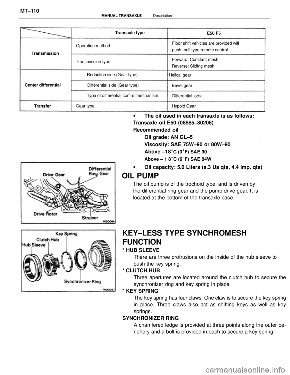
KEY±LESS TYPE SYNCHROMESH
FUNCTION
* HUB SLEEVE
There are three protrusions on the inside of the hub sleeve to
push the key spring.
* CLUTCH HUB
Three apertures are located around the clutch hub to secure the
synchronizer ring and key spring in place.
* KEY SPRING
The key spring has four claws. One claw is to secure the key spring
in place. Three claws also act as shifting keys as well as key
springs.
SYNCHRONIZER RING
A chamfered ledge is provided at three points along the outer pe-
riphery and a bolt is provided in each to secure a key spring. wThe oil used in each transaxle is as follows:
Transaxle oil E50 (08885±80206)
Recommended oil
Oil grade: AN GL±5
Viscosity: SAE 75W±90 or 80W±90
Above ±18
°C (0°F) SAE 90
Above ± 1 8°C (0°F) SAE 84W
wOil capacity: 5.0 Liters (s.3 Us qts, 4.4 Imp. qts)
OIL PUMP
The oil pump is of the trochoid type, and is driven by
the differential ring gear and the pump drive gear. It is
located at the bottom of the transaxle case.
Floor shift vehicles are provided will
push±pull type remote control
Forward: Constant mesh
Reverse: Sliding mesh
Type of differential control mechanismDifferential side (Gear type) Reduction side (Gear type) Transmission typeOperation method
Center differential. Helical gear
Differential lock Transaxle type
Hypoid Gear Transmission
Bevel gear
Gear type
TransferE56 F5
± MANUAL TRANSAXLEDescriptionMT±110
Page 2223 of 2389
HINT
wPerform all voltage and resistance measurements with the ECU connected.
wVerify that the battery voltage is 11 V or above with the ignition switch is ON.
Stop light SW ON (Brake pedal depressed) or defogger
SW ONNo trouble (ºCHECKº engine warning light off) and
engine running
Check connector TE 1 ± E 1 not connected
Specifications (Cont'd)
Check connector TE1 ± E1 connected
*1 W/O ECT *2 W/ EGT *3
A/C
EGR gas temp.
sensor
(CALIF.. only)
Ex. shift position P or N rangeIntake air temp. 205C (685F) Measuring plate fully closed
Coolant temp. 805C (1765F)
Shift position P or N rangeMeasuring plate fully open Throttle valve fully closed
Throttle valve fully closed
Heater blower SW ON Air conditioning ONThrottle valve open
Throttle valve open
Throttle valve open
Cranking or idlingSTD voltage (V)
3,000 rpmEG SW ON
IG SW ON IG SW ONIG SW ONIG SW ON
IG SW ON
Cranking
Terminals
Condition
Voltage
Idling
ECU
± SERVICE SPECIFICATIONSEFI System (3S±FE)A±12
Page 2224 of 2389
Fuel tank band x Body
Cold start injector x Air intake chamber
Cold start injector pipe x Cold start injector
Cold start injector pipe x Delivery pipe
Fuel pressure regulator X Delivery pipe
Fuel return pipe x Fuel pressure regulator
Delivery pipe x Cylinder head
Throttle body x Air intake chamberFuel evaporation vent tube x Fuel tank 4WD
Fuel inlet pipe x Fuel tankFuel sender gauge
Fuel pump X Fuel tank
Specifications (Cont'd)
Torque Specifications
Coolant temp. 805C (1765F) Intake air temp. 205C (685F) Measuring plate fully closed
Measuring plate fully openThrottle valve fully closed
Throttle valve fully closedThrottle valve fully closedThrottle valve fully closed
Throttle valve fully openThrottle valve fully open
* 1 w/o ECT *2 w/ ECT Throttle valve openThrottle valve open
Part tightened ECU (cont'd) Resistance
Condition
Fuel line
± SERVICE SPECIFICATIONSEFI System (3S±FE)A±13
Page 2227 of 2389
HINT:
wPerform all voltage and resistance measurements with the ECU connected.
wVerify that the battery voltage is 11 V or above with the ignition switch is ON.
No trouble (ºCHECKº' engine warning light off) and
engine running
Specifications (Cont'd)
Stop light SW ON (Brake pedal depressed)Check connector TE1 ± E1 not connected
Check connector TE1 ± Et connected
Shift position P or N range
Ex shift position P or N rangeIntake air temp. 205C (685F) Measuring plate fully closed
Coolant temp. 605C (1765F) Measuring plate fully open Throttle valve fully closed
Heater blower SW ON Air conditioning ONThrottle valve open
Throttle valve open
Cranking or idling Heater resistance
STD voltage (V) Oxygen
sensor
IG SW ON
IG SW ONIG SW ON
IG SW ONIG SW ON
IG SW ONCranking Terminals
Condition Voltage
Idling
*1 w/ rpm ECU
± SERVICE SPECIFICATIONSEFI System (2VZ±FE)A±15
Page 2228 of 2389

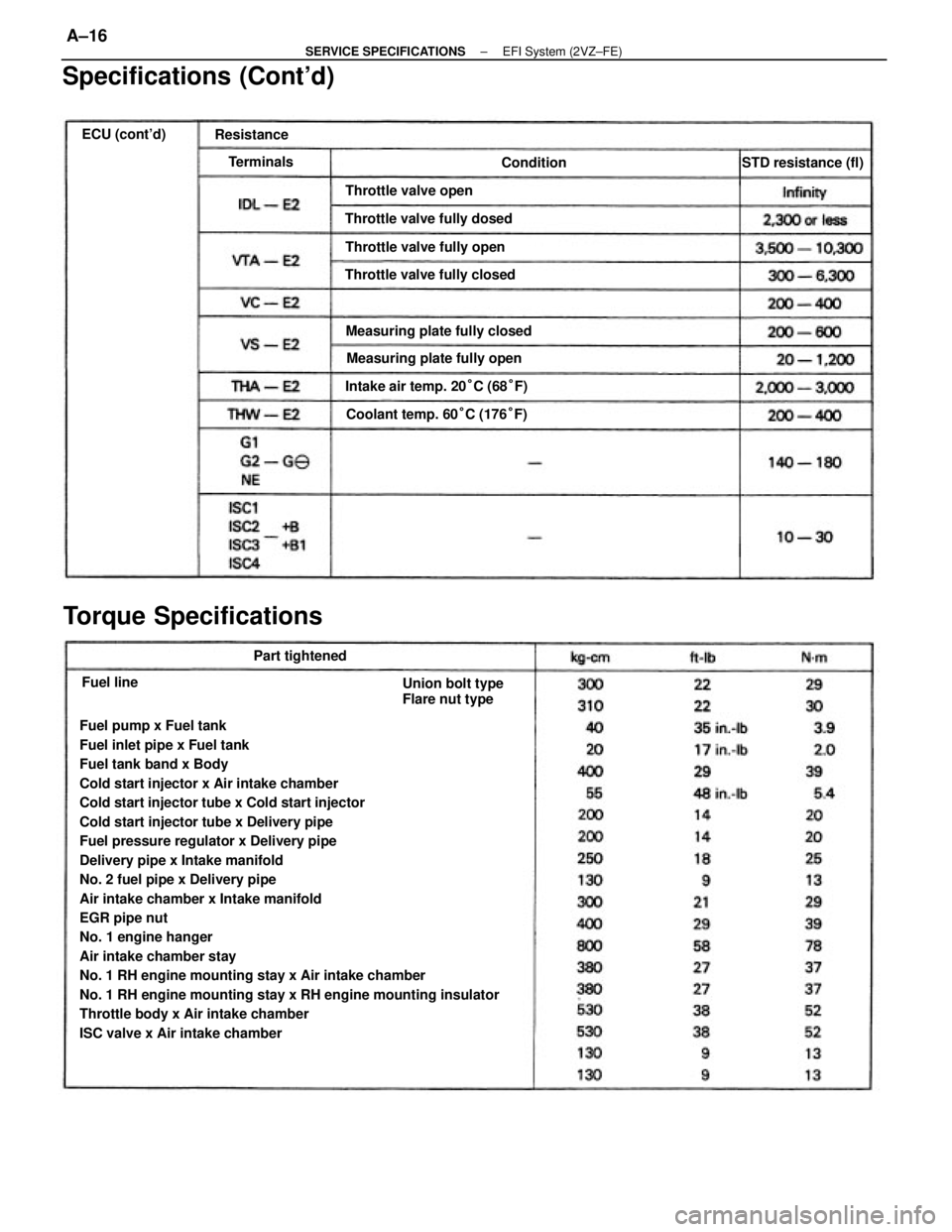
Fuel pump x Fuel tank
Fuel inlet pipe x Fuel tank
Fuel tank band x Body
Cold start injector x Air intake chamber
Cold start injector tube x Cold start injector
Cold start injector tube x Delivery pipe
Fuel pressure regulator x Delivery pipe
Delivery pipe x Intake manifold
No. 2 fuel pipe x Delivery pipe
Air intake chamber x Intake manifold
EGR pipe nut
No. 1 engine hanger
Air intake chamber stay
No. 1 RH engine mounting stay x Air intake chamber
No. 1 RH engine mounting stay x RH engine mounting insulator
Throttle body x Air intake chamber
ISC valve x Air intake chamber
Specifications (Cont'd)
Torque Specifications
Intake air temp. 20°C (68°F) Measuring plate fully closed
Coolant temp. 60°C (176°F)
Union bolt type
Flare nut type Measuring plate fully open Throttle valve fully dosed
Throttle valve fully closedThrottle valve fully open Throttle valve openSTD resistance (fl)
Part tightened ECU (cont'd)
Resistance
Terminals
Condition
Fuel line
± SERVICE SPECIFICATIONSEFI System (2VZ±FE)A±16
Page 2337 of 2389

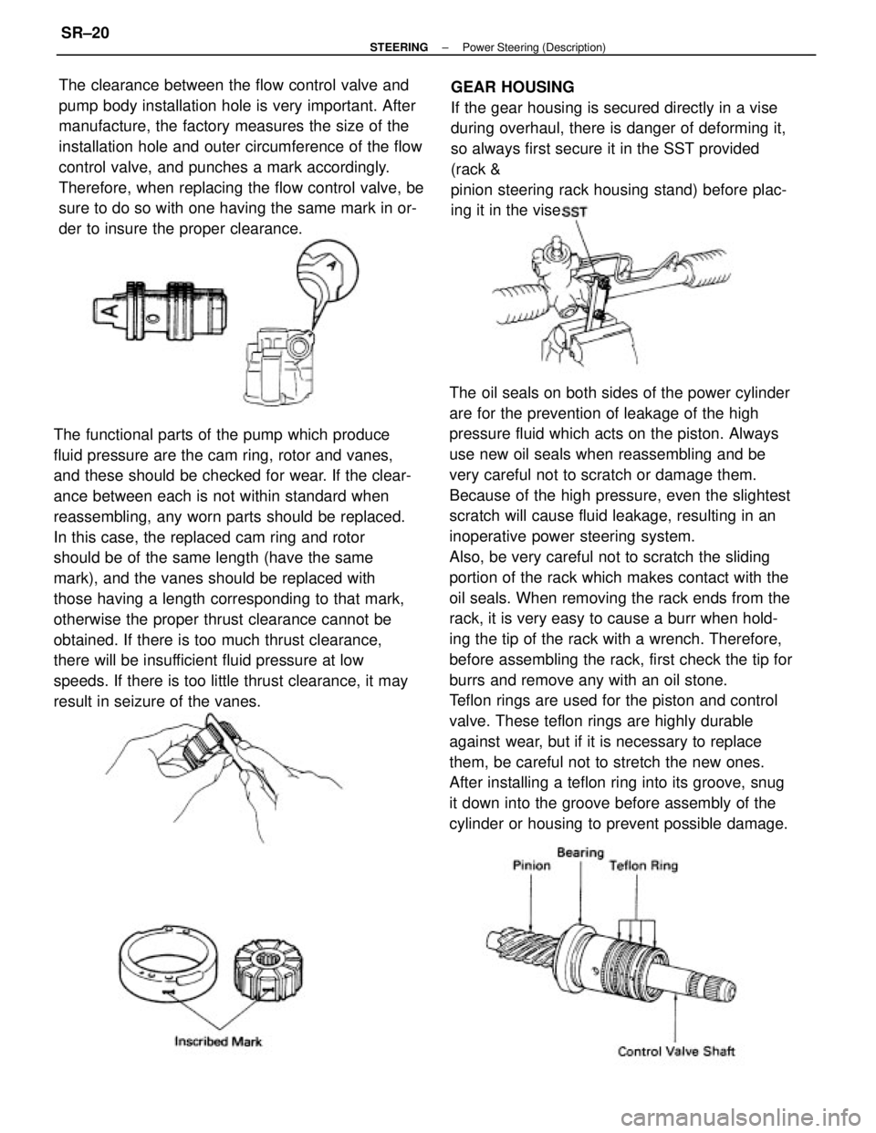
The oil seals on both sides of the power cylinder
are for the prevention of leakage of the high
pressure fluid which acts on the piston. Always
use new oil seals when reassembling and be
very careful not to scratch or damage them.
Because of the high pressure, even the slightest
scratch will cause fluid leakage, resulting in an
inoperative power steering system.
Also, be very careful not to scratch the sliding
portion of the rack which makes contact with the
oil seals. When removing the rack ends from the
rack, it is very easy to cause a burr when hold-
ing the tip of the rack with a wrench. Therefore,
before assembling the rack, first check the tip for
burrs and remove any with an oil stone.
Teflon rings are used for the piston and control
valve. These teflon rings are highly durable
against wear, but if it is necessary to replace
them, be careful not to stretch the new ones.
After installing a teflon ring into its groove, snug
it down into the groove before assembly of the
cylinder or housing to prevent possible damage. The functional parts of the pump which produce
fluid pressure are the cam ring, rotor and vanes,
and these should be checked for wear. If the clear-
ance between each is not within standard when
reassembling, any worn parts should be replaced.
In this case, the replaced cam ring and rotor
should be of the same length (have the same
mark), and the vanes should be replaced with
those having a length corresponding to that mark,
otherwise the proper thrust clearance cannot be
obtained. If there is too much thrust clearance,
there will be insufficient fluid pressure at low
speeds. If there is too little thrust clearance, it may
result in seizure of the vanes.The clearance between the flow control valve and
pump body installation hole is very important. After
manufacture, the factory measures the size of the
installation hole and outer circumference of the flow
control valve, and punches a mark accordingly.
Therefore, when replacing the flow control valve, be
sure to do so with one having the same mark in or-
der to insure the proper clearance.GEAR HOUSING
If the gear housing is secured directly in a vise
during overhaul, there is danger of deforming it,
so always first secure it in the SST provided
(rack &
pinion steering rack housing stand) before plac-
ing it in the vise.
± STEERINGPower Steering (Description)SR±20
Page 2347 of 2389

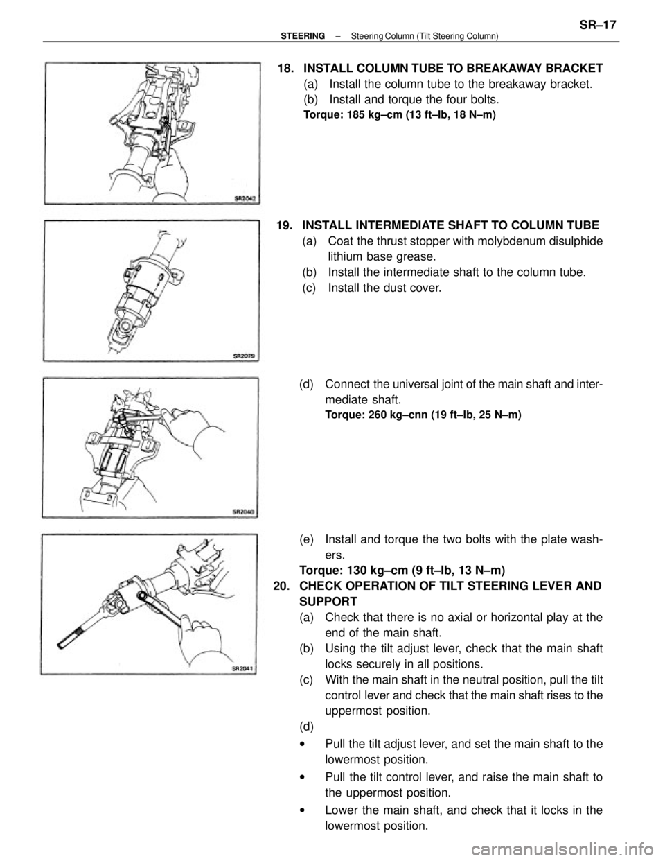
(e) Install and torque the two bolts with the plate wash-
ers.
Torque: 130 kg±cm (9 ft±Ib, 13 N±m)
20. CHECK OPERATION OF TILT STEERING LEVER AND
SUPPORT
(a) Check that there is no axial or horizontal play at the
end of the main shaft.
(b) Using the tilt adjust lever, check that the main shaft
locks securely in all positions.
(c) With the main shaft in the neutral position, pull the tilt
control lever and check that the main shaft rises to the
uppermost position.
(d)
wPull the tilt adjust lever, and set the main shaft to the
lowermost position.
wPull the tilt control lever, and raise the main shaft to
the uppermost position.
wLower the main shaft, and check that it locks in the
lowermost position. 19. INSTALL INTERMEDIATE SHAFT TO COLUMN TUBE
(a) Coat the thrust stopper with molybdenum disulphide
lithium base grease.
(b) Install the intermediate shaft to the column tube.
(c) Install the dust cover. 18. INSTALL COLUMN TUBE TO BREAKAWAY BRACKET
(a) Install the column tube to the breakaway bracket.
(b) Install and torque the four bolts.
Torque: 185 kg±cm (13 ft±Ib, 18 N±m)
(d) Connect the universal joint of the main shaft and inter-
mediate shaft.
Torque: 260 kg±cnn (19 ft±Ib, 25 N±m)
± STEERINGSteering Column (Tilt Steering Column)SR±17
Page 2377 of 2389
DISASSEMBLY OF STEERING GEAR
HOUSING
1. CLAMP GEAR HOUSING IN VISE
Using SST secure the steering gear in a vise.
SST 09612±00012
2. REMOVE RIGHT AND LEFT TURN PRESSURE TUBES
Using SST, remove the pressure tubes.
SST 09633±20
COMPONENTS
± STEERINGPower Steering (Gear Housing)SR±51