Page 1924 of 2389
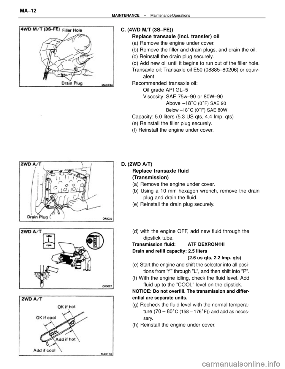
C. (4WD M/T (3S±FE))
Replace transaxle (incl. transfer) oil
(a) Remove the engine under cover.
(b) Remove the filler and drain plugs, and drain the oil.
(c) Reinstall the drain plug securely.
(d) Add new oil until it begins to run out of the filler hole.
Transaxle oil: Transaxle oil E50 (08885±80206) or equiv-
alent
Recommended transaxle oil:
Oil grade API GL±5
Viscosity SAE 75w±90 or 80W±90
Above ±18
°C (0°F) SAE 90
Below ±18°C (0°F) SAE 80W
Capacity: 5.0 liters (5.3 US qts, 4.4 Imp. qts)
(e) Reinstall the filler plug securely.
(f) Reinstall the engine under cover.
(d) with the engine OFF, add new fluid through the
dipstick tube.
Transmission fluid: ATF DEXRON�II
Drain and refill capacity: 2.5 liters
(2.6 us qts, 2.2 Imp. qts)
(e) Start the engine and shift the selector into all posi-
tions from ºf'º through ºLº, and then shift into ºPº.
(f) With the engine idling, check the fluid level. Add
fluid up to the ºCOOLº level on the dipstick.
NOTICE: Do not overfill. The transmission and differ-
ential are separate units.
(g) Recheck the fluid level with the normal tempera-
ture (70 ± 80
°C (158 ± 176°F)) and add as neces-
sary.
(h) Reinstall the engine under cover. D. (2WD A/T)
Replace transaxle fluid
(Transmission)
(a) Remove the engine under cover.
(b) Using a 10 mm hexagon wrench, remove the drain
plug and drain the fluid.
(e) Reinstall the drain plug securely.
± MAINTENANCEMaintenance OperationsMA±12
Page 1925 of 2389
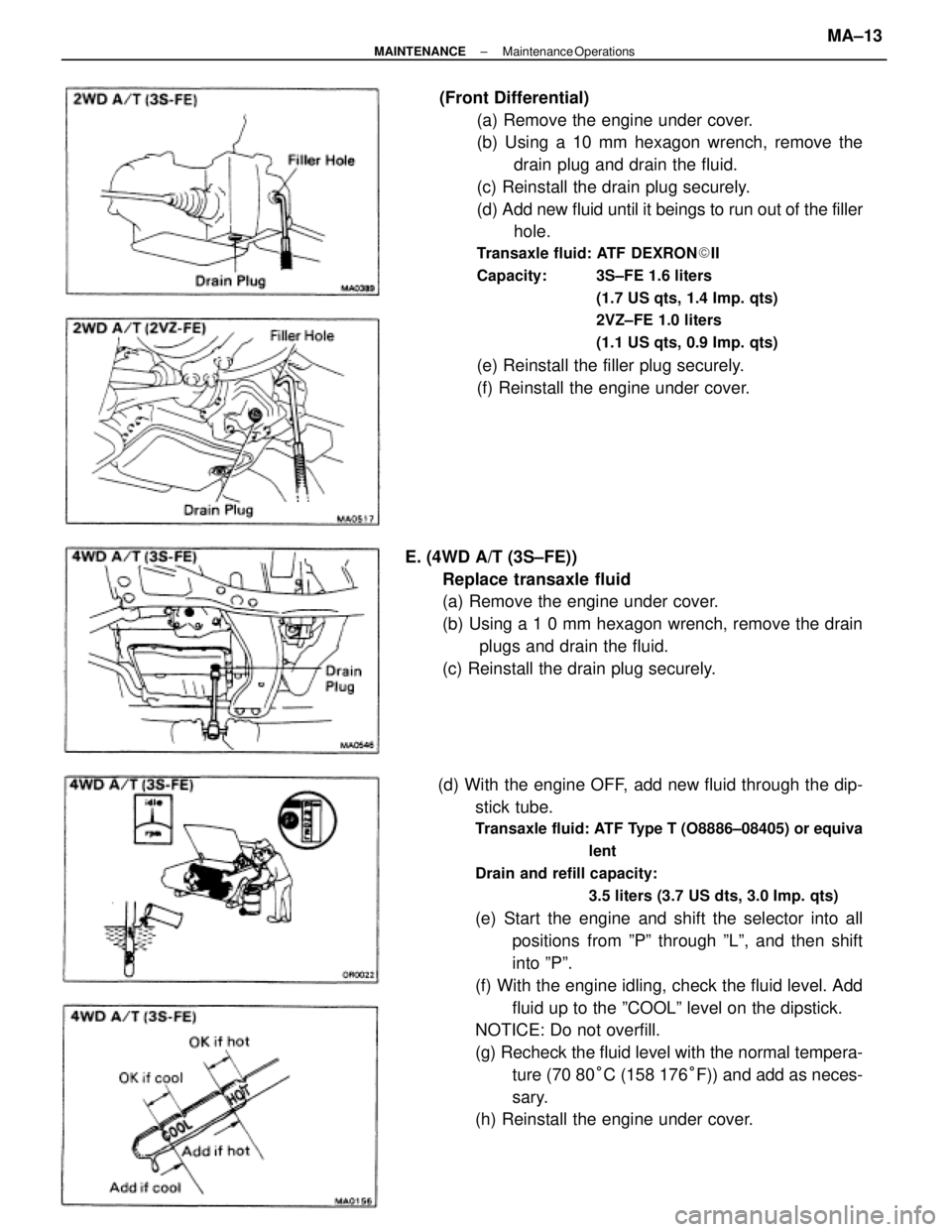
(Front Differential)
(a) Remove the engine under cover.
(b) Using a 10 mm hexagon wrench, remove the
drain plug and drain the fluid.
(c) Reinstall the drain plug securely.
(d) Add new fluid until it beings to run out of the filler
hole.
Transaxle fluid: ATF DEXRON�II
Capacity: 3S±FE 1.6 liters
(1.7 US qts, 1.4 Imp. qts)
2VZ±FE 1.0 liters
(1.1 US qts, 0.9 Imp. qts)
(e) Reinstall the filler plug securely.
(f) Reinstall the engine under cover.
(d) With the engine OFF, add new fluid through the dip-
stick tube.
Transaxle fluid: ATF Type T (O8886±08405) or equiva
lent
Drain and refill capacity:
3.5 liters (3.7 US dts, 3.0 Imp. qts)
(e) Start the engine and shift the selector into all
positions from ºPº through ºLº, and then shift
into ºPº.
(f) With the engine idling, check the fluid level. Add
fluid up to the ºCOOLº level on the dipstick.
NOTICE: Do not overfill.
(g) Recheck the fluid level with the normal tempera-
ture (70 80°C (158 176°F)) and add as neces-
sary.
(h) Reinstall the engine under cover. E. (4WD A/T (3S±FE))
Replace transaxle fluid
(a) Remove the engine under cover.
(b) Using a 1 0 mm hexagon wrench, remove the drain
plugs and drain the fluid.
(c) Reinstall the drain plug securely.
± MAINTENANCEMaintenance OperationsMA±13
Page 1926 of 2389
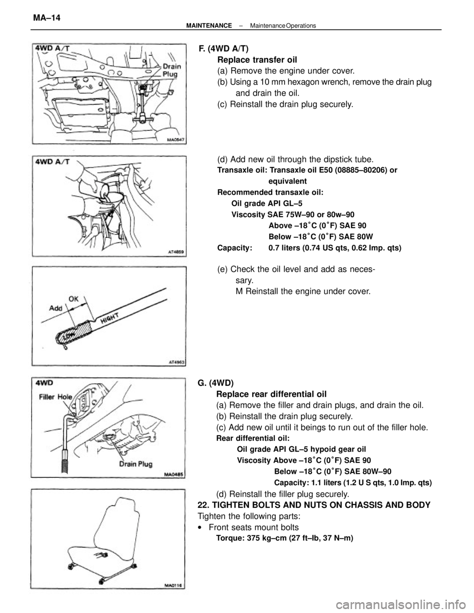
G. (4WD)
Replace rear differential oil
(a) Remove the filler and drain plugs, and drain the oil.
(b) Reinstall the drain plug securely.
(c) Add new oil until it beings to run out of the filler hole.
Rear differential oil:
Oil grade API GL±5 hypoid gear oil
Viscosity Above ±18°C (0°F) SAE 90
Below ±18°C (0°F) SAE 80W±90
Capacity: 1.1 liters (1.2 U S qts, 1.0 Imp. qts)
(d) Reinstall the filler plug securely.
22. TIGHTEN BOLTS AND NUTS ON CHASSIS AND BODY
Tighten the following parts:
wFront seats mount bolts
Torque: 375 kg±cm (27 ft±Ib, 37 N±m)
(d) Add new oil through the dipstick tube.
Transaxle oil: Transaxle oil E50 (08885±80206) or
equivalent
Recommended transaxle oil:
Oil grade API GL±5
Viscosity SAE 75W±90 or 80w±90
Above ±18°C (0°F) SAE 90
Below ±18°C (0°F) SAE 80W
Capacity: 0.7 liters (0.74 US qts, 0.62 Imp. qts)
F. (4WD A/T)
Replace transfer oil
(a) Remove the engine under cover.
(b) Using a 10 mm hexagon wrench, remove the drain plug
and drain the oil.
(c) Reinstall the drain plug securely.
(e) Check the oil level and add as neces-
sary.
M Reinstall the engine under cover.
± MAINTENANCEMaintenance OperationsMA±14
Page 1927 of 2389
23. FINAL INSPECTION
(a) Check the operation of the body parts:
wHood
Auxiliary catch operation properly
Hood locks securely when closed
wFront and rear doors
Door locks operate properly
Doors close properly
wLuggage compartment door and back door
Door sock operates properly
wSeats
Seat adjusts easily and locks securely in any position
Front seat back locks securely in any position
Folding±down rear seat backs lock securely
(b) Road test
wCheck the engine and chassis for abnormal noises.
wCheck that the vehicle does not wander or pull to one side.
wCheck that the brakes work properly and do not drag.
wPerform bedding down of the parking brake shoes and drum.
(See page MA±8)
(c) Be sure to deliver a clean car especially check:
wSteering wheel
wShift lever knob
wAll switch knobs
wDoor handles
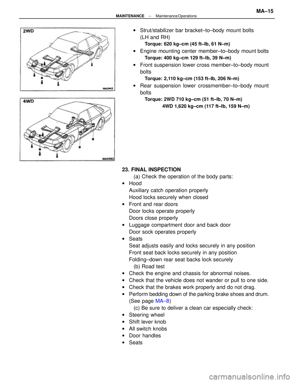
wSeatswStrut/stabilizer bar bracket±to±body mount bolts
(LH and RH)
Torque: 620 kg±cm (45 ft±lb, 61 N±m)
wEngine mounting center member±to±body mount bolts
Torque: 400 kg±cm 129 ft±lb, 39 N±m)
wFront suspension lower cross member±to±body mount
bolts
Torque: 2,110 kg±cm (153 ft±Ib, 206 N±m)
wRear suspension lower crossmember±to±body mount
bolts
Torque: 2WD 710 kg±cm (51 ft±lb, 70 N±m)
4WD 1,620 kg±cm (117 ft±Ib, 159 N±m)
± MAINTENANCEMaintenance OperationsMA±15
Page 1932 of 2389
7. REMOVE TRANSAXLE MOUNTING BOLTS OF
TRANSAXLE UPPER
8. RAISE VEHICLE
NOTICE: Be sure the vehicle is securely supported.
9. REMOVE UNDER COVERS
10. DRAIN OUT FLUID
11. DISCONNECT SPEEDOMETER CABLE
S51 TRANSMISSION
REMOVAL OF TRANSAXLE
1. REMOVE NEGATIVE BATTERY CABLE
2. REMOVE CLUTCH RELEASE CYLINDER AND TUBE
CLAMP
5. REMOVE STARTER
(a) Disconnect the cable and connector.
(b) Remove the starter with the two bolts.
6. DISCONNECT BACK±UP LIGHT SWITCH
CONNECTOR AND GROUND STRAP 3. REMOVE±.CLUTCH TUBE BRACKET
(a) Remove the retainer from the bracket.
(b) Remove the bolt and bracket.
4. DISCONNECT CONTROL CABLES
(a) Remove the clips and washers.
(b) Remove the retainer from the cables.
± MANUAL TRANSAXLES51 TransmissionMT±4
Page 1938 of 2389
DISASSEMBLY OF TRANSMISSION
(See pages MT±7 to 9)
1. REMOVE RELEASE FORK, BEARING, BACK±UP
LIGHT SWITCH AND SPEEDOMETER DRIVEN
GEAR
2. REMOVE RELEASE BEARING RETAINER
3. REMOVE TRANSMISSION CASE COVER
4. REMOVE NO. 3 SHIFT FORK SECURING BOTH
5. MEASURE FIFTH GEAR THRUST CLEARANCE
Using a dial indicator, measure the thrust clear-
ance.
Standard clearance: 0.20 ± 0.40 mm
(0.0079 ± 0.0157 in.)
Maximum clearance: 0.45 mm (0.0177 in.)
(b) Using SST and remove the No. 2 lock ball.
SST 09313±30021
7. REMOVE SELECTING BELLCRANK 6. REMOVE NO. 1 AND NO.2 LOCK BALL ASSEMBLIES
(a) Loosen the lock nut and remove the No. 1 lock ball.
8. REMOVE SHIFT AND SELECT LEVER ASSEMBLY
± MANUAL TRANSAXLES51 TransmissionMT±10
Page 1952 of 2389
INSTALLATION OF TRANSAXLE
1. INSTALL TRANSAXLE TO ENGINE
Align the input shaft spline with the clutch disc, and
install the transaxle to the engine. Torque the bolts.
Torque:
12 mm bolt 650 kg±cm (47 ft±lb, 64 N±m)
10 mm bolt 470 kg±cm (34 ft±Ib, 46 N±m)
2. CONNECT LEFT ENGINE MOUNTING
Connect the left engine mounting with the bolts. Torque
the bolts.
Torque: 530 kg±cm (38 ft±lb, 52 N±rm)
3. INSTALL STABILIZER BAR
(See page FA±35)
4. INSTALL CENTER DRIVE SHAFT
(a) Insert the center drive shaft to the transaxle through the
bearing bracket.
(b) Secure the center drive shaft with the snap ring.
(c) Tighten a new bolt on the bearing bracket.
Torque: 330 kg±cm (24 ft±lb, 32 N±m)
5. CONNECT BOTH DRIVE SHAFTS
Connect the drive shaft and torque the six nuts while de-
pressing the brake pedal.
Torque: 370 kg±cm (27 ft±Ib, 36 N±m)
6. CONNECT LEFT STEERING KNUCKLE TO LOWER
ARM
Torque: 1,150 kg±cm (83 ft±Ib, 113 N±m)
± MANUAL TRANSAXLES51 TransmissionMT±38
Page 1967 of 2389
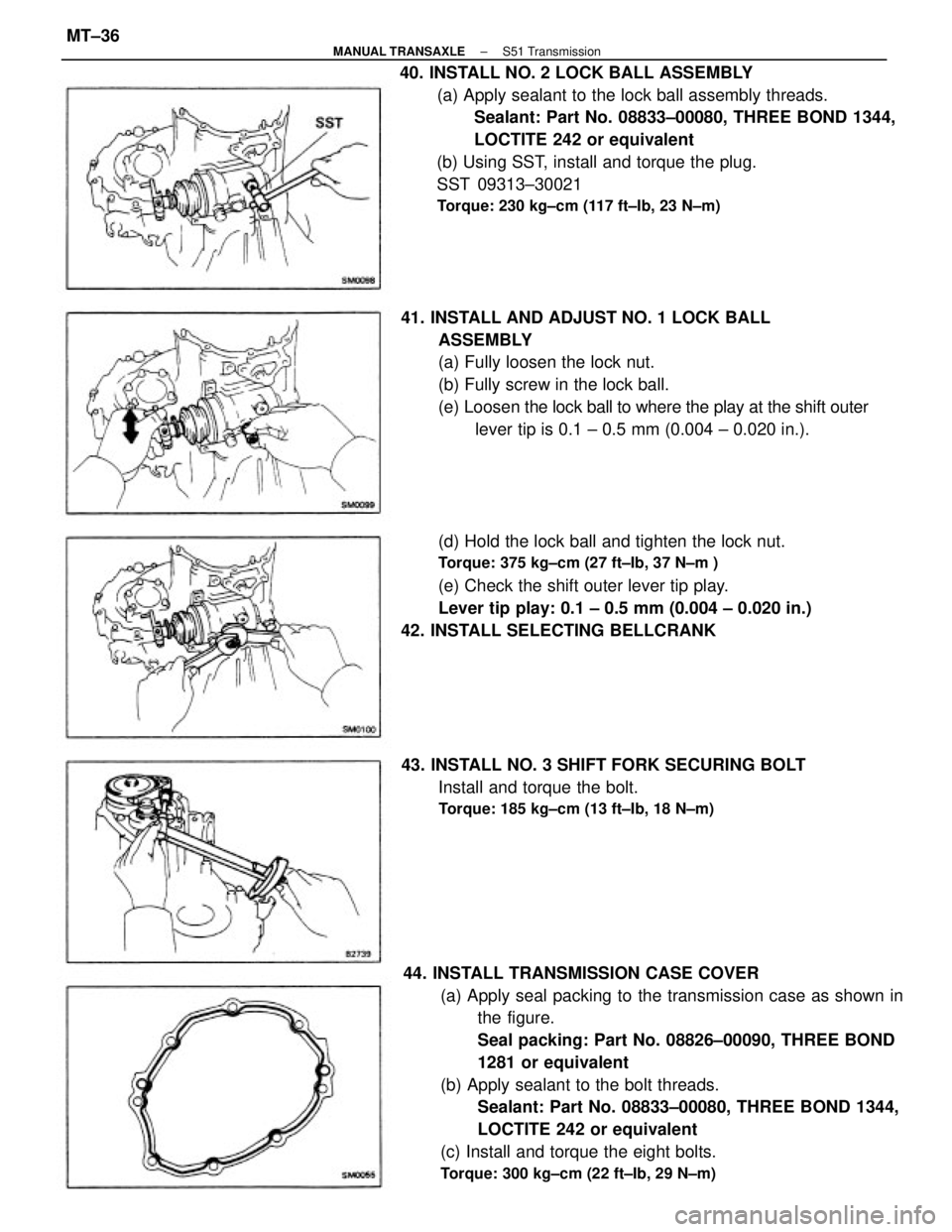
44. INSTALL TRANSMISSION CASE COVER
(a) Apply seal packing to the transmission case as shown in
the figure.
Seal packing: Part No. 08826±00090, THREE BOND
1281 or equivalent
(b) Apply sealant to the bolt threads.
Sealant: Part No. 08833±00080, THREE BOND 1344,
LOCTITE 242 or equivalent
(c) Install and torque the eight bolts.
Torque: 300 kg±cm (22 ft±Ib, 29 N±m)
40. INSTALL NO. 2 LOCK BALL ASSEMBLY
(a) Apply sealant to the lock ball assembly threads.
Sealant: Part No. 08833±00080, THREE BOND 1344,
LOCTITE 242 or equivalent
(b) Using SST, install and torque the plug.
SST 09313±30021
Torque: 230 kg±cm (117 ft±Ib, 23 N±m)
41. INSTALL AND ADJUST NO. 1 LOCK BALL
ASSEMBLY
(a) Fully loosen the lock nut.
(b) Fully screw in the lock ball.
(e) Loosen the lock ball to where the play at the shift outer
lever tip is 0.1 ± 0.5 mm (0.004 ± 0.020 in.).
(d) Hold the lock ball and tighten the lock nut.
Torque: 375 kg±cm (27 ft±Ib, 37 N±m )
(e) Check the shift outer lever tip play.
Lever tip play: 0.1 ± 0.5 mm (0.004 ± 0.020 in.)
42. INSTALL SELECTING BELLCRANK
43. INSTALL NO. 3 SHIFT FORK SECURING BOLT
Install and torque the bolt.
Torque: 185 kg±cm (13 ft±Ib, 18 N±m)
± MANUAL TRANSAXLES51 TransmissionMT±36