Page 1860 of 2389

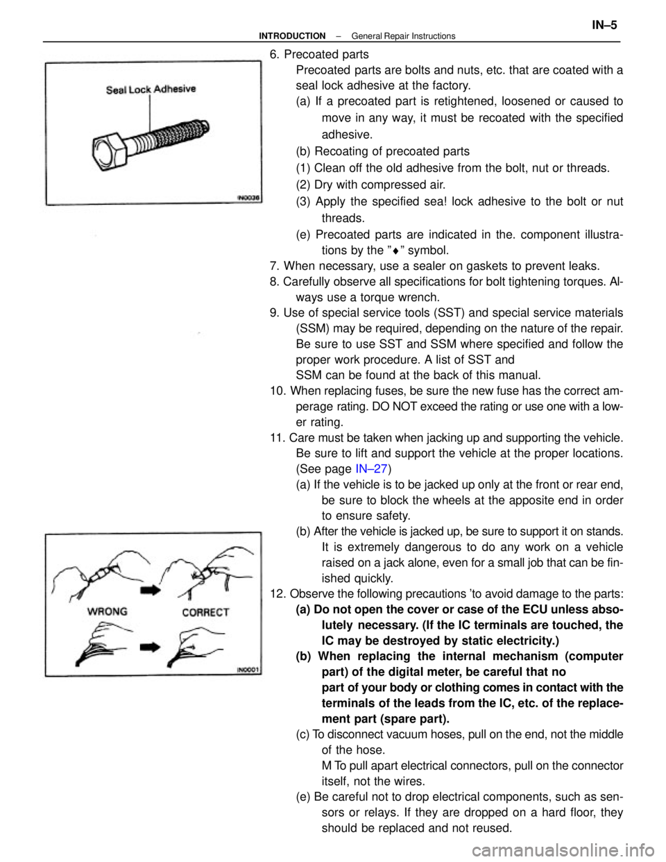
6. Precoated parts
Precoated parts are bolts and nuts, etc. that are coated with a
seal lock adhesive at the factory.
(a) If a precoated part is retightened, loosened or caused to
move in any way, it must be recoated with the specified
adhesive.
(b) Recoating of precoated parts
(1) Clean off the old adhesive from the bolt, nut or threads.
(2) Dry with compressed air.
(3) Apply the specified sea! lock adhesive to the bolt or nut
threads.
(e) Precoated parts are indicated in the. component illustra-
tions by the ºrº symbol.
7. When necessary, use a sealer on gaskets to prevent leaks.
8. Carefully observe all specifications for bolt tightening torques. Al-
ways use a torque wrench.
9. Use of special service tools (SST) and special service materials
(SSM) may be required, depending on the nature of the repair.
Be sure to use SST and SSM where specified and follow the
proper work procedure. A list of SST and
SSM can be found at the back of this manual.
10. When replacing fuses, be sure the new fuse has the correct am-
perage rating. DO NOT exceed the rating or use one with a low-
er rating.
11. Care must be taken when jacking up and supporting the vehicle.
Be sure to lift and support the vehicle at the proper locations.
(See page IN±27)
(a) If the vehicle is to be jacked up only at the front or rear end,
be sure to block the wheels at the apposite end in order
to ensure safety.
(b) After the vehicle is jacked up, be sure to support it on stands.
It is extremely dangerous to do any work on a vehicle
raised on a jack alone, even for a small job that can be fin-
ished quickly.
12. Observe the following precautions 'to avoid damage to the parts:
(a) Do not open the cover or case of the ECU unless abso-
lutely necessary. (If the IC terminals are touched, the
IC may be destroyed by static electricity.)
(b) When replacing the internal mechanism (computer
part) of the digital meter, be careful that no
part of your body or clothing comes in contact with the
terminals of the leads from the IC, etc. of the replace-
ment part (spare part).
(c) To disconnect vacuum hoses, pull on the end, not the middle
of the hose.
M To pull apart electrical connectors, pull on the connector
itself, not the wires.
(e) Be careful not to drop electrical components, such as sen-
sors or relays. If they are dropped on a hard floor, they
should be replaced and not reused.
± INTRODUCTIONGeneral Repair InstructionsIN±5
Page 1873 of 2389
2. REMOVE MODE SELECT LEVER LOCK BOLT
3. MOVE MODE SELECT LEVER TO DESIRED MODE
POSITION
While rotating one front wheel by hand, shift the select lever
towards the LOCK mode or FREE mode.
HINT: Do not use excessive force when moving the mode
select lever.
4. AFTER MAKING SHIFT, LOCK MODE SELECT LEVER
SECURELY WITH BOLT
HINT: Be sure to tighten the lock bolt securely each time after
moving the mode select lever.(4) Depress the brake pedal, shift into L range and gradu-
ally release the brake pedal.
(5) Check that the front wheels begin to rotate and that the
rear wheels do not rotate.
2. Moving Mode Select Lever
1. JACK UP VEHICLE(6) Stop the engine and put the transmission in N range.
± INTRODUCTIONPrecautions When Servicing Full±Time 4WD VehiclesIN±16
Page 1874 of 2389

CAUTIONS WHEN MODE SELECT LEVER IS IN ºFREEº
OR ºLOCKº MODE
FREE MODE
(1) Do not drive off suddenly or apply the accelerator or
brakes suddenly. Always start slowly and decelerate
gradually.
(2) If either the front or the rear wheels are placed on the
tester rollers in the FREE mode, be careful not to exceed
the following limits:
Maximum speed:
Speed indicated on speedometer
19 mph(30 km/h) or
Wheel speed (Tester speed)
38 mph160 km/h)
Maximum test time: 60 sec.
Note that the actual wheel speed (tester speedy is twice the
speed indicated by the speedometer due
to center differential operation.
LOCK MODE
(1) Do not drive off suddenly or apply the accelerator or
brakes suddenly. Always start slowly and decelerate
gradually.
(2) Be sure to conduct the test with the rear propeller
shaft removed.6. AFTER FINISHING TEST, RETURN MODE SELECT
LEVER TO ºFREE (NORMAL)º MODE POSITION AND
LOCK SELECT LEVER SECURELY WITH BOLT
7. SET CENTER DIFFERENTIAL CONTROL SWITCH TO
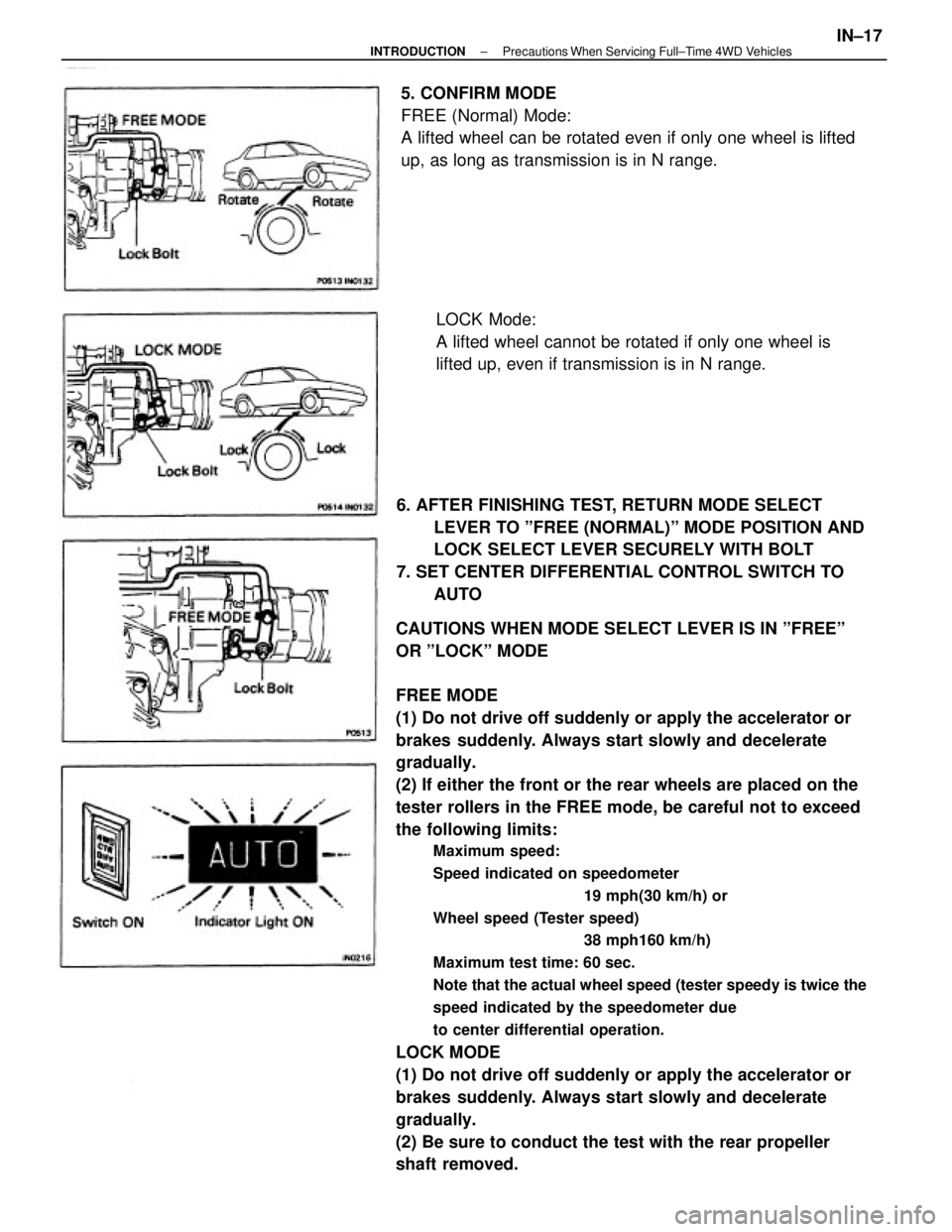
AUTO 5. CONFIRM MODE
FREE (Normal) Mode:
A lifted wheel can be rotated even if only one wheel is lifted
up, as long as transmission is in N range.
LOCK Mode:
A lifted wheel cannot be rotated if only one wheel is
lifted up, even if transmission is in N range.
± INTRODUCTIONPrecautions When Servicing Full±Time 4WD VehiclesIN±17
Page 1875 of 2389

BRAKING FORCE TEST
HINT: According to the vehicle speed during the test, select
one of the two test methods described below, either A or B.
Method A : Conduct the test with the center differen±
(Low Speed Test) tial control switch oft and the select lever
on the transaxle in the FREE (Normal)
mode.
Method B : Conduct the test with the center differen±
(High Speed Test) tial control switch off, the select lever on
the transaxle in the LOCK mode and the
rear propeller shaft removed.
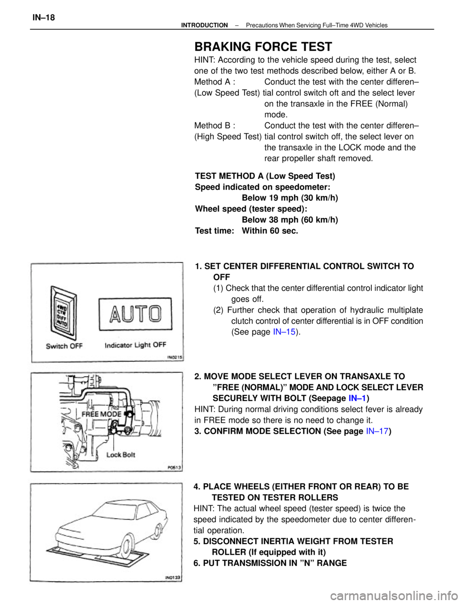
4. PLACE WHEELS (EITHER FRONT OR REAR) TO BE
TESTED ON TESTER ROLLERS
HINT: The actual wheel speed (tester speed) is twice the
speed indicated by the speedometer due to center differen-
tial operation.
5. DISCONNECT INERTIA WEIGHT FROM TESTER
ROLLER (If equipped with it)
6. PUT TRANSMISSION IN ºNº RANGE1. SET CENTER DIFFERENTIAL CONTROL SWITCH TO
OFF
(1) Check that the center differential control indicator light
goes off.
(2) Further check that operation of hydraulic multiplate
clutch control of center differential is in OFF condition
(See page IN±15).
2. MOVE MODE SELECT LEVER ON TRANSAXLE TO
ºFREE (NORMAL)º MODE AND LOCK SELECT LEVER
SECURELY WITH BOLT (Seepage IN±1)
HINT: During normal driving conditions select fever is already
in FREE mode so there is no need to change it.
3. CONFIRM MODE SELECTION (See page IN±17) TEST METHOD A (Low Speed Test)
Speed indicated on speedometer:
Below 19 mph (30 km/h)
Wheel speed (tester speed):
Below 38 mph (60 km/h)
Test time: Within 60 sec.
± INTRODUCTIONPrecautions When Servicing Full±Time 4WD VehiclesIN±18
Page 1876 of 2389
![TOYOTA CAMRY V20 1986 Service Information TEST METHOD B (High Speed Test)
[Vehicle speed: Over 38 mph (60 km/h)]
1. SET CENTER DIFFERENTIAL CONTROL SWITCH TO
OFF
(1) Check that the center differential control indicator light
goes oft.
(2) Fur TOYOTA CAMRY V20 1986 Service Information TEST METHOD B (High Speed Test)
[Vehicle speed: Over 38 mph (60 km/h)]
1. SET CENTER DIFFERENTIAL CONTROL SWITCH TO
OFF
(1) Check that the center differential control indicator light
goes oft.
(2) Fur](/manual-img/14/57449/w960_57449-1875.png)
TEST METHOD B (High Speed Test)
[Vehicle speed: Over 38 mph (60 km/h)]
1. SET CENTER DIFFERENTIAL CONTROL SWITCH TO
OFF
(1) Check that the center differential control indicator light
goes oft.
(2) Further check that the operation of the hydraulic multi-
plate clutch control of the center differential is in
OFF condition.
(See page IN±15)
2. MOVE MODE SELECT LEVER ON TRANSAXLE TO ºLOCKº
MODE AND LOCK IT SECURELY WITH BOLT
(See page IN±16)
3. CONFIRM MODE SELECTION
(See page IN±17) 7. OPERATE TESTER ROLLERS AND MEASURE
BRAKING FORCE WITH ENGINE AT IDLE
HINT: Since different types of tester are used, such as spe-
cialized brake testers and combination testers with built in
chassis dynamometer, speedometer tester, brake tester, etc.,
conduct the test in accordance with the instructions furnished
for the tester model used.
4. REMOVE REAR PROPELLER SHAFT
Make matching marks on each end of the propeller shaft,
then remove it.8. AFTER FINISHING TEST, RETURN CENTER
DIFFERENTIAL CONTROL SWITCH TO ºAUTOº AND
CHECK THAT INDICATOR LIGHT GOES ON
± INTRODUCTIONPrecautions When Servicing Full±Time 4WD VehiclesIN±19
Page 1877 of 2389
5. PLACE WHEELS (EITHER FRONT OR REAR) TO BE
TESTED ON TESTER ROLLERS
6. CHOCK OTHER WHEELS
7. DISCONNECT INERTIA WEIGHT FROM TESTER ROLL-
ER (if equipped with it)
8. PUT TRANSMISSION IN N RANGE
9. OPERATE TESTER ROLLERS AND MEASURE
BRAKING FORCE WITH ENGINE AT IDLE
HINT: Since different types of tester are used, such as
specialized brake testers and combination testers with
builtin chassis dynamometer, speedometer tester, brake test-
er, etc., conduct the test in accordance with the instructions
furnished for the tester in use.
10. AFTER FINISHING TEST, INSTAL! REAR PROPELLER
SHAFT
Align the matching marks made on the rear propeller shaft
before removal, then install it.
11. RETURN MODE SELECT LEVER TO ºFREE (NORMAL)º
MODE POSITION AND LOCK IT SECURELY WITH
BOLT
12. SET CENTER DIFFERENTIAL CONTROL SWITCH TO
AUTO
± INTRODUCTIONPrecautions When Servicing Full±Time 4WD VehiclesIN±20
Page 1878 of 2389
![TOYOTA CAMRY V20 1986 Service Information SPEEDOMETER TEST OR OTHER TESTS
[Using Speedometer Tester or Chassis Dynamometer]
1. SET CENTER DIFFERENTIAL CONTROL SWITCH TO
OFF
(1) Check that the center differential control indicator light
goes TOYOTA CAMRY V20 1986 Service Information SPEEDOMETER TEST OR OTHER TESTS
[Using Speedometer Tester or Chassis Dynamometer]
1. SET CENTER DIFFERENTIAL CONTROL SWITCH TO
OFF
(1) Check that the center differential control indicator light
goes](/manual-img/14/57449/w960_57449-1877.png)
SPEEDOMETER TEST OR OTHER TESTS
[Using Speedometer Tester or Chassis Dynamometer]
1. SET CENTER DIFFERENTIAL CONTROL SWITCH TO
OFF
(1) Check that the center differential control indicator light
goes oft.
(2) Further check that the operation of the hydraulic
multiplate clutch control of the center differential is in
OFF condition.
(See page IN±15)
2. MOVE MODE SELECT LEVER ON TRANSAXLE TO ºLOCKº
MODE AND LOCK IT SECURELY WITH BOLT (See page
IN±16)
3. CONFIRM MODE SELECTION
(See page IN±17)
8. DISCONNECT INERTIA WEIGHT FROM TESTER ROLL-
ER (If equipped with it)
9. TEST VEHICLE
(1) Start the engine.
(2) Put the transmission in D range, then gradually in-
crease the speed as the test in conducted.
(3) After the test is finished, reduce the speed gradually
and stop the engine. 4. REMOVE REAR PROPELLER SHAFT
Make matching marks on each end of the rear propeller
shaft, then remove it.
5. PLACE FRONT WHEELS ON TESTER ROLLERS
6. CHOCK REAR WHEELS
7. APPLY PARKING BRAKE
10. AFTER FINISHING TEST, INSTALL REAR PROPELLER
SHAFT
Align the matching marks made on the rear propeller shaft
before removal, then install it.
± INTRODUCTIONPrecautions When Servicing Full±Time 4WD VehiclesIN±21
Page 1879 of 2389
11. RETURN MODE SELECT LEVER TO ºFREE
(NORMAL)º MODE POSITION AND LOCK IT
SECURELY WITH BOLT
12. SET CENTER DIFFERENTIAL CONTROL SWITCH TO
AUTO
± INTRODUCTIONPrecautions When Servicing Full±Time 4WD VehiclesIN±22