Page 145 of 205

144 Chapter 9 Braking systom
9 II there Dre no inspec tion holes, remove the wheels and drums In inspect the linings . 10 Where any lining is less Ih,111 the nllnimufll thickness, renew Ihp. complete SCI 01 re,ll b,~ke shoes. 11 Refi ' the drums lind wheels as necessary then lowe. tho em \0 thl) 9lOund.
Ch eck operation of servo lIoil 12 Visually inspCCllhe vaCUUll1 hose IClIding hom the inlet mlllllfolll Of air box 10 the servo unit fOf dc\c,iOf1l1lon and security. 13 Wit h the engine Slopped. dCI).es s the bra ke pedal several ,imes to dissipate t he VOC U\Ull hoUl the sorvo Imit. 14 Depress the b'i1kc 11Cdll1 wilh moderate pressure then Sin' I the
cnU illC . As the V
L ubrietl!£! /wndbh7ke linkage 15 Jilck up Ihe .eolf of Ihe Colf illid SIIIIPOII on ilxle Slilnds . 16 Oltthe prim,uy eil!>le connOChon to the boltom of Ihe halldh';,~" level. 17 011 1974/1975 models. u,ease Ihe pflmolfy callie whe,e II p;,sses over Ihe pulley wheel. ,111(1 0,1 Ihe pull ey ilnd lever pivot pO"'IS . 18 On lillCr models grease Ihe 1,i1nw c.se rod SUI)I)Olt hC;lfinU 19 011 the clcv is IIUIS i1I the w", l>olckpl" ,es. 20 lower thc cm !O the gr ound
R/mew fhe /)rilke I/Ilid 21 lJIucd Ihe hyd.; ."loc sySle m as d"scllherl III Seelloll 15 ilUOwnl! II",
Ihe new h ,,,k\) Ih"d to COnlph: lely 1,lIlhe C:"CUtt he"I!1 bled . 22 AI Ihe sanl\) I"ne rcn,uve Ihe 'Ci" ",ake \I'lOn,s alld check tho wlu,,,1
cylonclers 10' leak"IJe.
3 Front disc pl1ds - renewal
Apply t
he handbr
I
I .
. ~ .. " ,) •. :Y.
2 RemOV(l Ihe hont wheels.
3 It Ihe fhnd level in the maste' cylondel reservoir is high. when the pistons l1re moved into thei, respecI,ve bo,es to accommodate new pi1ds. thO leyel could rise sulticienlly fo, Iho fluid 10 oyerflow. Place ilhsoruent clOlh .1round the reSe,yO". o. syphon a Imlo Ituid oul. so 1)'Cven tUlg Pil"ltwOlk
hOld the m;"n ,clalfl,ng pins in plilce (photo) 5 RemOYfl Ihe m"in le tainm g pin~ which ,un through Iho c.lliper and the mel,, 1 h.,r. krnn of th o pads and Ihe ShUllS. 6 The flll ;t, o n l),le1S cil n now bo removed from the cahper. If they prnv!! \III1ICIIII to ,emove by Iland . II pair of long·nosed pi ie,s can be lIscd Lill :Iway the shims and tens.on sPflnus (whe,e lilted) (phoIOS). 7 Ca.eh,liy clcall Ihe .ecesses in the cahl>Of in which Ihe h,ction pads :md ShUllS he. and Ihe exposed faces 01 caCh pis ton. rem oving allu3ces 01 d"t 0' rllst 8 Us",u a p,nte 01 wood. e.l,eh,lIy rUlI,1et Ihe pis tons. n 1'1,11;\1 IhH t",'~e p"d tens,on SI""'U" Oil Ihe hr~ke 1)o1ds i1fl
'''~'''''''" ;,S n,~:"sS,l'y
<1 F rollt brake caliper _ rcmoy'll iltld refitting
1 nemove the f,on! disc pads i1S tie sc"lJc(/ in Section 3. 2 1111 'S Itll,,,,d,,(1 10 lit ncw Ci1tiper pistoll s "nd/o, seals. dep,ess the tH.1k'J Iwel,,1 10 hlUlU the pistons i"to COI11i1ct with thO (fisc and
3 .4 A pad .et
.>.6C Disc pad and shim 3.9A T he shim allow must lace tho forwa,d rotation o f Ihe f.ont wheel
'-.. ~
, .
3 .9B Fitting the tenS ion springs
.--.::.:.:; .
....... . ~,'
灲潣慲浡湵慬献捯m
Page 146 of 205
 Chapter 9 Braking system 145
/ll.Iid reservoir tille , cap \0 help roduce any fluid loss. 4 Where a rigi d brake line is connec ted \0 the calipe r, comple tely unscrOw the union nUl . Where I")
) Chapter 9 Braking system 145
/ll.Iid reservoir tille , cap \0 help roduce any fluid loss. 4 Where a rigi d brake line is connec ted \0 the calipe r, comple tely unscrOw the union nUl . Where Iho flex ible hose is connected directly \0 Ihe caliper. loosen only .he union (lnd unscrew Ihc caliper f.om Ihe
hose later. S Prise back the laus on the locking plale and unscrew Ihe mouming boilS (photo). The cJliper may now be wit hdrawn ove r th o disc and where neCessary unscrew ed from Ihc flex ible hose, 6 Refilling is a revCfsal of fernOv;!I, but lit a new locking plate and
l ighten the mouming bol ts \0 the specified torque. Bend the Inbs \0 Io<:k I he boils. On comple tion bleed the hydwulic system wit h
reference \ 0 Sec tion 15.
5 Front brake caliper -ovorlulU l
1 With the c~liper removed . cle~n away all external dlr1. 2 Where applicable, prise out the dust cover cirClips
dust covers from the external ~onular groove. : lIr"ct the pistons: keeping them idenhlied side lor s.de. If nt .... "ss"ry. use low [lir P"CSSlU(! frOill a foot pump to lorc e the pistons
IrOIl' lho bores. 4 nove tho dust covers Irom the pistons or bores as apphc
hydrau lic Uuid . Inspect the piSlons and bores for signs 01 weilr . score markS. or damage and il evident. new par ts should be obtained !Cady for lilting. or a new ca lipe r obtained. 7 R eassem ble tho components using a reversal of th n disnwn tling procedure. but before inserting the pis tons dip them in clen n hydrnulic fluid to assist entry through the seals. On comple tion press the pistons fully into the bores.
45 Front brake caliper mounting bolts (arrowed)
6 Front brake discs -in spection. re rnovnl and refitting
Apply the hilndlxake then jn ck up the hom of the car and support on :1xle st:1flds. Remove the Iront roadwheels . 2 Rotate the disc by hand and examine il lor deep scoring, grooving or cf1lcks. light scoring is normal, but if excessive the disc must be
renewed.
3 SCrJpe
RUEO '.(RlW
--
1-""£0""""" ~Plf'l ~-____ ttIP
BI"'~( ".",~"" PI~I()'
4IOUf llltlGOOLI tCCKltlG PLATE
R( 1 Altl{R RltlG
BRAKE (VLIHOER PISTO'l
(l001
Fig. 9.3 EKp loded view of the front brake calipe( on fater models (Sec 5)
RING
., .,
,
procarmanuals.com
Page 147 of 205

Chapter 9 Braking system
4 Note that in order to m,lintOIll even braking both discs should he renewed ill the sal1 1 e lime
5 T o remove il dl~c. first remove the tHlb as described in Chllpter 10 . 6 Prise lip th(J locklllU I"hs. unscrew the fOlll bolts. and remove the disc from Ihe huh.
7 Clcilll the Illllirnu !ilces of the disc and hub then locale the diSC on the huh and allgel the holt holes.
8 InScrt new holt~. tOI){)ther w rth new locking plates. and tiuhten them to the specrfre(1 torque_ loc k b y bending the tabs. 9 Th e huh Illily now he ref Illed with reference to Chapter 10.
7 ReM hrake shoes -rt)rlewal
Check the front wheels th!:n lilck up the rem of the CM lind support on ,1~le stands. Rel(,a5e Ihe handbr,lke lind femove the reM roadwh~~els
2 Unsr",w th" I"ake drum lewinrnu scrow then t.1p off the ,IIurn \Jsing ;I ~"It f.lced milliet (photos) 3 Barsh away all dust I.orll the brilke shoos, backplate ilnd drum, ",killfl can' ""I /0 11111""., II ;I S 1/ is iHjmiaus to "e,11Ih Del""~~ ,,;och shoe hold-down sprrng (photo) ,lnt! rOt,lte the sprrn!! ",w"nIlH w.r~I"" th,ou!lh 90" , to rhsengage ,t from the pm sel:rr",d 10 Ihe had' pt. 'I" 1.,11 ,"wily 1Ill! w;'shel and spm}!J
Early moth'ls (iippmxilllawly pm Df!c()tllbcf 1974) 5 Eas,) .. ad} shoe loom ,t~ loc;rllol1 slor III the lixed pivot nrrd tllen detach th,-othe! '~nd 01 ea(.11 shoe f,om the wheel cylind'lr, 6 Note whld, W.1Y fOwul and IIltO which holus in the s hoes tlH~ two retracting sP""Hs Ill. 7 lift ,lway t ho two brake shoes "nd retracting springs. 8 TUf(lthe self- ad lust'ng ratchot wheetum,1 it alJuts the shoulder on t he s lot head bolt.
FiO_ 9.4 Renr brake shoo components Oil e,lrly moclnfs (Sec 7 )
I Pili 'm froft! dowII sWIIIII 2 Buc/."liTlt! J B',l~'l! shot's <1 II,-IIIrflHiiAe opcra/jllY h-v", 5 lIo/d d"wII slNil/ys
Lawf lII oduls
6 fir"",,:, (/",,1 r:lJvlH 7 IId;III1I1'!IIII.llr!S 8 flNr;Il:IIl'!! .,'I,"IIIIS 9 WI",,:II:yllJldl!l
fJ N Ole the local,on of the shoe 1"lpacl,no sprrll!ls nrld thell unllook tlwm \lSUl!l a s(;lewrh,vef or SUil;!tJle plo~"s. Remuv,) th" lorw,lrd shoe Unhuok tho small pelurn spring loom the reill shoe and then rumuve the shoe lenvinlJ the adJus!Cr in pos,tiol} (ph o tos)_ 10 Tu remove tim adjuster unit. del
'nech
7.2A Re
cylinder (later models) 7.98 Brake shoe attachment to anchor ( later models) 7.10 Halldbr~ ke tra nsverse rod connection to opera ting lever on backp!ilte (Jrlowed)
,
j
procarmanuals.com
Page 148 of 205

Chapter 9 Braking system 147
Br;'lke IlIlInU
Wheel Adjustment
"m
cylinder --·-·_.L
-::'~~:.J/
I
'j
~
l
~
• shoe hold down spring/pin
Br.lke shoe
Fig. 9
.5 Rear brake shoe components on later m odels (Sec 7)
All models 11 Check the wheel cylinder lor leaks and lor Ioee moyemen t of the
piston(s). Apply a hule brake urease to Ihe shoe contac t points on the
backpla te. wheel cylinde r, anchOr and sell-adjusting mechanism. On
early models check th
12 Fit the new brilke shoes using a reyers .. 1 01 the remoyal procedure,
but check that the self-.. djusting mechanism is set to the minimum
posi tion belore refilling the drum .
13 Finilily apply lhe loo tbrake firmly several times. On later models this will actua1e the self-adjus ting mechanism; however. on e
'
Wheel cylinder _ remo yal. oyerhaul and re fitting
Remove lhe rear urake shoes as described in Section 7.
2 Fit a hose clalllp to the fle~ible hose leading to the reaf br .. kes. If a hose ci
4 On pre Oecembe r 1974 models remoye the split pin and clevis pin Irom the handb rake leyer
the spr ing plate is inser ted from the piston end 01 the wheel cylinder.
5 On I.ller models unbolt the wheel cylinde r from the backplate .
6 To dismantle thO wheel cylinder, remoye the clip where fitted then
prise the rubber boo t(s) from the cylinder body.
7 Extr.lct the piston( s)
8 Remoye the piston return spring .
9 Prise the seal(s) from the piston(s) , 10 Clean all thO compo nents in methylated spirits or clean hydraulic fluid then inspec t them for wea r and damage. Check the cylinder bote and piston{s) 10f scoring and corrosion. and il eviden t renew the
complete w heol cylinder. If the components are in good condition
ob tain a repair kit 01 seals.
i.
i I
II
j
I ;
procarmanuals.com
Page 149 of 205
8 Chapter 9 Braking system
8
Fig. 9 .6 Rear wheel cylinder component s on \"\",I y models (Sec 8)
I Cft,} 2 Rubber hoot 3 Pis/oil
5 Relmll SfJflflY 6 Blcell screw 9 Scff \",,uSilll!! wtdll.:/ 10 At")
)8 Chapter 9 Braking system
8
Fig. 9 .6 Rear wheel cylinder component s on "",I y models (Sec 8)
I Cft,} 2 Rubber hoot 3 Pis/oil
5 Relmll SfJflflY 6 Blcell screw 9 Scff ",',uSilll!! wtdll.:/ 10 At/jlls/my boof
4 Seal I Retaming JlI,~tcs II Ullfufb,;,Ac oj/cUlling level 8 Wheel cyhirdcr body
11 Dip the piSlOn(s) and plSlOn SC
12 Rein the wheel cyhnder using il f(lversal of Ihe fcmOy.1. procedure. Note lhal on (l,lIly models t he sel l.,ldrusI1I19 .atchet is handed -RH thread on the RH side. and Lit thread on thc LH SIde. 13 On cOlllpletion bleed the hydraulic syslCHll ;'IS described in Section 15.
9 ROilr backl}lato -rClllovn! (IIHI mfittillg
Remove th ... wheel cylllllier ~s
Thoroughly cle,ln the b~ckpl.1te ~nd Jxll) casing Ihen relit the h .. 1ckplJte with reference to ChJpter 8 Jnd Section 8 01 this CIl.1pler.
Fig. 9.7 Re .. r whoel cylinder components on lilter models (Sec 8)
1 Rubber boots 2 Se'lls 3 PiS/OilS 4 Re/vm spring
5 Wheel cylinder body 6 Bleed screw 7 OVSI cover
1 0 MJsle r cylinder -rcmov;11 Jnd refitting
P lace a ~wllcIH'hJe COI11~lIler benem h Ihe mJ$le f cylinde r 10 cmch ,1ny spIlled Ihud ... Mil also place ~on,e cloth on Ihe surrounding hodywork ;lml componems 2 Disco"nect Ihe wirinlJ lrom the low tluid winni,,!) sw,tch on the ,evelvoir 1,lh.1I r:ap (photo).
3 UIlSI:f(lW lill) reservoir 1011111 cap and dr"w out the flui(1 using J syphon or sucl'o" l(,be <1 Unsocw ("u un'on Illl(S IOnd rlist:onncct Ihe b,ake lines. 5 Unscrew lOud r emove (ill) nlolUwng nulS and washers Jnd lilt the mnster cyl",du' hom Ihe Siuds Oil Ih e servo lmll. G Empty llin tlu,d 11010 llie con l,urlcr Jnd remove the master cylinder
from Ihe enU",e comp(lrtmeni. Io1k,ng cllre nOI 10 spill Iluid on the bodywolk. 7 HeliuinU 's II ,eve'slIl of removJI. but on completion bleed the hydraulic syslem IIS (Iescribed In Section 15.
10.2 Disconne cting the low lIuid warning switch wiring
procarmanuals.com
Page 150 of 205
 clean the exterior sudaces.
Girling type 2 Removo the SCleW$ and withdraw rhe fl")
1 Chapter 9 Braki ng system 1 49
,1 M aste r cylinder -overhaul
With tho m
Girling type 2 Removo the SCleW$ and withdraw rhe fluid reservoir. twisting i as necesS,,'y from Ihe end seal. 3 Remove the twO seals afler cdraC ling the circlip ovor Ihe cnd seal. <1 Using II hOKagon key. unscrew Ihe relainer and hit oUllhe primary
recuperating valvo. Oepress Ihe primll'y piston during Ihis procedure. 5 Exl.;'!ct Ihe primary and secondary pistons. IOgether wi,h their associated components. noting Ihe order of lemOlln l. H nccessary top Ihe master cylinder on a block of wood or use air pressure from il foot pUIllP through the inlel porlS. G Separate rhe primmy ,10d secondary l)is10 11S irani lha intermediilte
sprinu . Uso tho !inUe.s 10 remove tile Ulilnd seDI from the primil'Y
r""' lon .
The secondil'y piSlon assembly should ho sOfh"ated by lilting the u"mblo leaf ove , Ihe shouldered cnd 01 tho viston . Using the lingo,s.
rr 'wo the se
spnJlg
9 Dotach lhe villve space ,. tilking c
Teves (ATE) type 10 Dopress Ihe primary piston, thon oxtrnCtlhe circlip from the mOUlh of th o c ylindo r and also unscrew Ille SlOp screw. 11 Extract the primary piston componen ts noting Ihe order 0 1 removal. followed by Ihe secondary piston componenlS. If necessary top the
master cylinder on a block of wood or use air pressure from a 1001 pump through tho inlet ports. 12 Prise the seals from the pistons, nOling which way round they are lilled. then il necessary remove tho springs and seals. The prima ry
pis ton spring is retained by a screw.
Both types 13 Clean all tho components in melhylated spirits or brake fluid then
inspec t them for wear and damage. Check the cylinder bore and pistons for scorinu and corrosion. and if eviden t renew the complete nI
.opair kit of seals. 14 Di p Ihe piston and seills in hydrilulic Iluid then reassemble Ihe m
convex side against Ihe shoulder nange. Belore refiuing the fluid reservoi r on lhe Girling type ch ock that the recupera ling valve is open wllh Ihe prim
depressed.
1
2~
3~
13
1
2
3
4 5 6
7 8
R
22
21
Fig. 9
.8 Exploded view 01 the Girlin g master cylinder (Sec 11)
Filler cap 9 Seal 16 Secondary piston
Seal 10 MaSler cylinder body 17 Seal
Seal !Clainer
11 WiJslrer 18 Rell11i1er
Fluid reservoi r 12 Reservoir relaining screw 19 Spring
Seal
1 3 Seal 20 Spring fl/Miner
Relainer
14 Primary piSlon 21 Valve
Primary fCCllpCfaling valve
15 Spring 22 Seal
Circlip
10
!
" 1 ,
1
I
!
!
I ,
J
,[
1
I
I
; .
!I ' i ;.
procarmanuals.com
Page 151 of 205

STOP WASHEP. WASHE R
PRIMARY ~ ()
CUP PISTON ~lJ ~
SPRIN\G SEAT T 1 WASt")
,
.00 Chapter 9 Braking system
PR IMARY CUP
SeCONDARY J CUP _ RETA INER SCREW
INTERMEDIATE RING
SECONDAR Y CUP)
STOP WASHEP. WASHE R
PRIMARY ~ (''''')
CUP PISTON ~lJ ~
SPRIN\G SEAT T 1 WAStE:~L~\C Q I~
PRl~lARY CUP ./
SPRING OISC I -1 '" "'~'f" SPRING i SEAT L ,:-\,/(.'.~·, J ' '
RETAINER • \ . '0 I)J-'0'.'.)'. ',:.,' "'f
I -, " ,O"'j')'" I' . I r -h" .
l J i\\"\" ,jl;
~G«1N w: 1 vl";';':' ~ .. '
" r • • {l"t:';" ,: .• ,-; \{. . ' SNAP . \J, ~;'. PISTON RING
--
1\-\1 ijM:\'.' ,J , ~1.1"9 _ ·S TOP SCREW .....
--
SEAL ','
-'---
WASHEA
---, ,
/ /
SECONDARY CUP
Fig. 9 .9 EKplodcd view of tho Teves (ATE) master cylinder (Sec 11)
, •..•.• -." . I',
- --
I
'-- ----
---"Ii
-,
I
~J
- . ' , ..... (
F ig 9.10 The Tavos (ATE) maste r cylinder pisto ns as sembled ready fo r reliUing (Sec 11)
12 Pressure di Herent;al switch -desctilHion. removal and refitting
E,lrly mOdels were filled with a pre ssure diHerent ial switch to illurnin~to ~ wolfning l igh t on the in stru men t pilnel in the event 01 a drop in preSsure in eithe/the Iron t 0/ rear hydraul ic circui ts . The switch ir- "'rporates 1I piSton which is kept 'in b alanco' if the pres sures in tho I. and roar ci,cui ts are equal. Howeve/, rl there is a pressure drop in
one circuit. t he pisto n is displaced and the switc h con tacts close .
2 The switc h is loca ted on tha lowe, left .hand side of the eng ine comp,Htrnent and a lthough it was once possible \0 obtain new in ternal
seals these are no longer available. Th e switch may be renewed alone (without Iho hyd,au lic body) by disconnecting the wiring and unsc rewing it .
3 To rernovo the hydraulic body. first tigh t
en a piece 01 polythene shoetinu bene ath th e brako Iluid reservoir fillor cap 10 reduce th a loss 01 fluid .
4 D isconnec t the swit ch wiring.
5 Unscrew the fi
ve union nuts thon disconnec t and plug the pipes.
6 UnSCfew the mouming bolt and romove the unit.
7 Relillin g is a reversa l of removal. but on comple tion bleed the hydraulic system as described in Section 15 .
procarmanuals.com
Page 152 of 205

Chapter 9 Braking system
,,-
\")_J ,
: ~~ 11111JIII/IIIJ II /I /III Ii hIIllllIlIlIllllIlll 11111#111111 III! -------
8
9
Fig. 9.11 Exploded view o f Iho pressure d ifferenti<ll switch (Sec 1")
-
)
Chapter 9 Braking system
,,-
")_'J ,
: ~~ 11111JIII/IIIJ II /I /III Ii hIIllllIlIlIllllIlll 11111#111111 III! -------
8
9
Fig. 9.11 Exploded view o f Iho pressure d ifferenti
I Fron( /)',l/a.' inlet ullioll 2 W ,)Silms 3 Pj~(UflS
J Pressure reducing vulve -description. remalln' nnd refitting
<1 SCi/Is 5 W,If/ll//y $wl(ch (j [lid ilIIIY
All models from ~pproxirniltely 1978 me lilted with il pressure ,educing valve in the rC~f hydraulic Cifelli!. The IInlve is IOCillCd on the lower Icft- hJrHJ side of the engine compn((mcnt (phOIO) ,mel 11 effectively limIts the hrakin\1 force DV
4 Unscrew the twO union nuts then disconnect ~nd pluU the pipes .
5 Unscrew the mounting bolts ,md remove the unit.
6 Refitting is a reversal of removal, but on completion bleed the
hydraulic system as descrihed in Section 15.
1 4
Hydraulic pipes and hoses -removal and refittin g
7 8.1/1 8 Body 9 R(lb/w( cover
First wke meilsures to reduce the loss 01 hydraulic fluid. If ~ rig id
pipe downstream of a fle~ible hose is being removed fit ~ hose clamp to
the hose . If this is not possible tighten a piece 01 polythene sheetinu
beneath th e livid reservoi r filler cap. 13
.1
Rear brake pressure reducing valve
2 To femove a figid pipe, unscrew the union nutS;]1 each cnd and release the pipe from the retaining ctrps. wh(Jre /riled.
be retained as a gUide.
151
)TO remove 11 fle~ible hose, lirst disconnec t the rigid pipes IN u"screwing the union nuts then unscrew the nuts securing the hose to
the 1l10unting brackets .
4 RiUid brake pipes arc normally made up from straight pipe using special bending <.rnd flare· forming lools. The old pipe should therefore 5
Refitt ing
is J revNsal o f removal, but make sure thJtlle~ible hoses
arc positioned clear of suspension or steering cOlilpo rwnts which
could chafe them. Finally bleed the hydrauhc system as deSCribed in Section 15.
••
procarmanuals.com
 1
1 2
2 3
3 4
4 5
5 6
6 7
7 8
8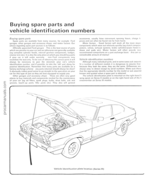 9
9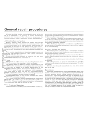 10
10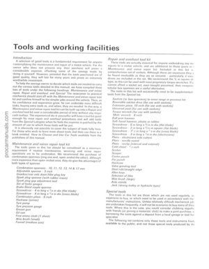 11
11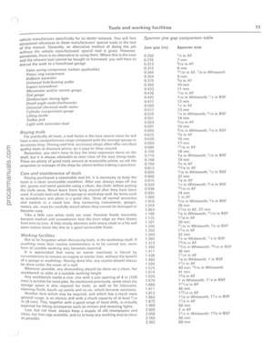 12
12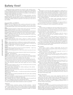 13
13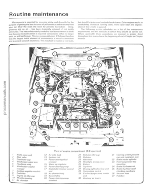 14
14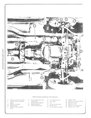 15
15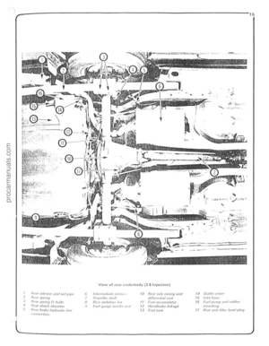 16
16 17
17 18
18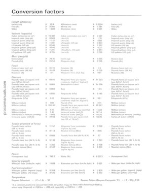 19
19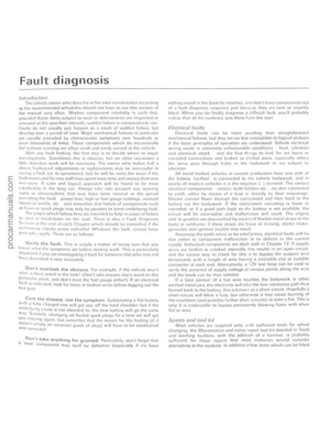 20
20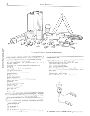 21
21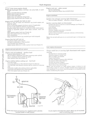 22
22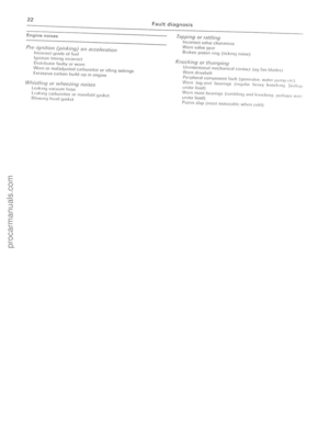 23
23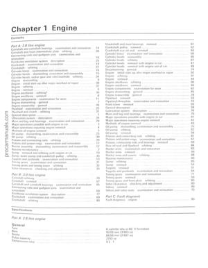 24
24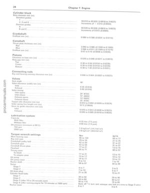 25
25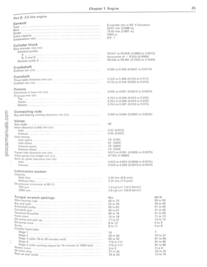 26
26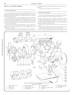 27
27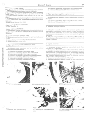 28
28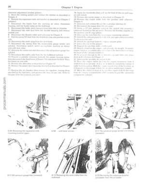 29
29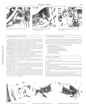 30
30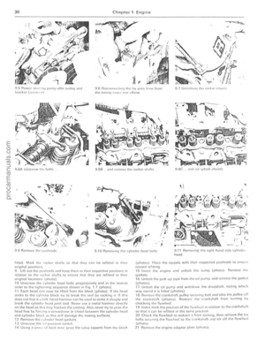 31
31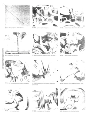 32
32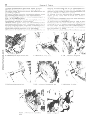 33
33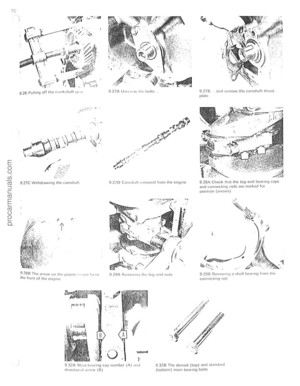 34
34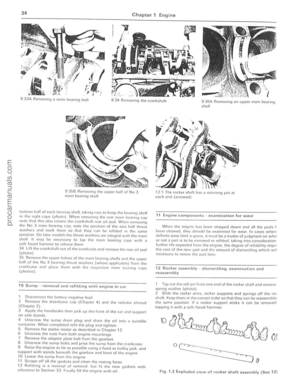 35
35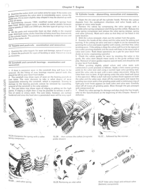 36
36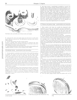 37
37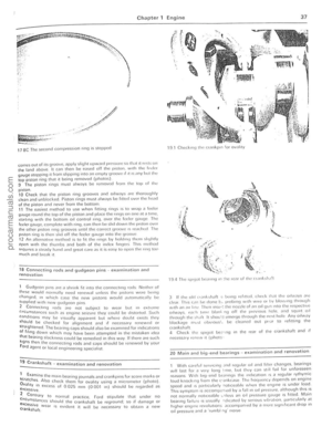 38
38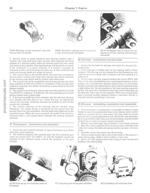 39
39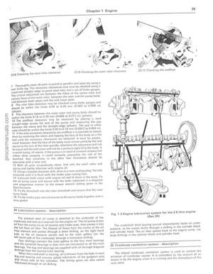 40
40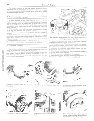 41
41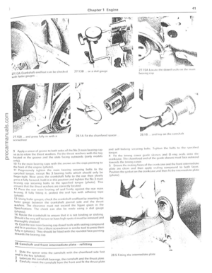 42
42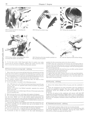 43
43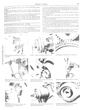 44
44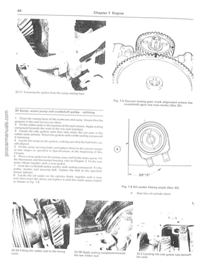 45
45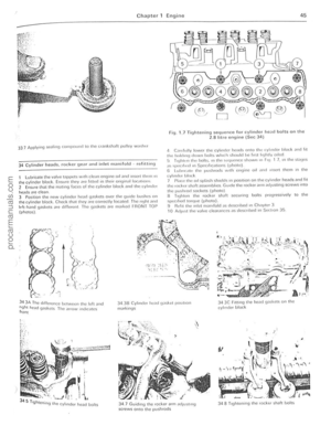 46
46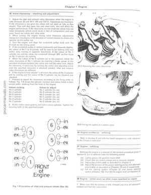 47
47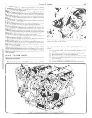 48
48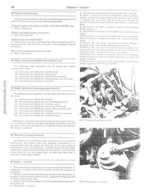 49
49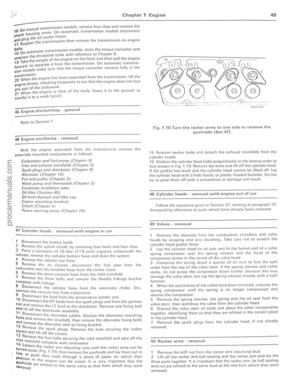 50
50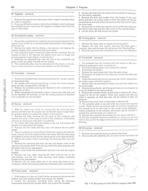 51
51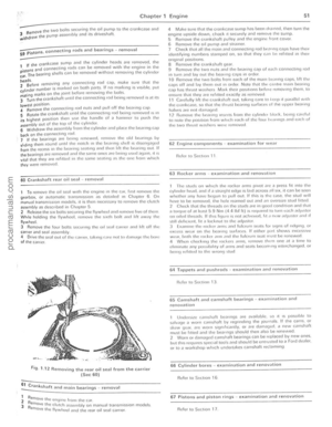 52
52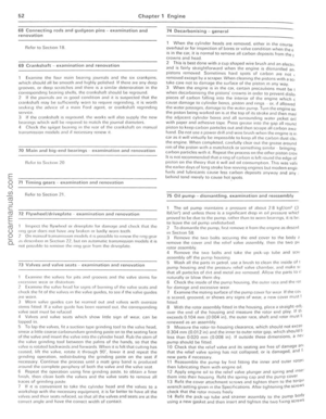 53
53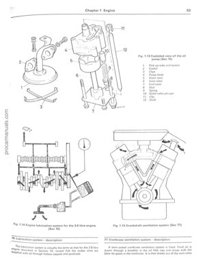 54
54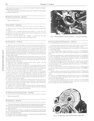 55
55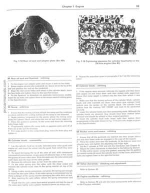 56
56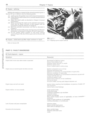 57
57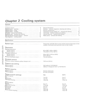 58
58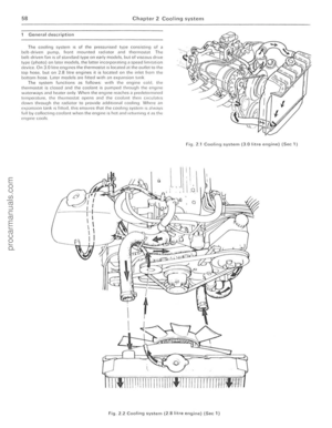 59
59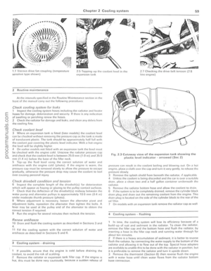 60
60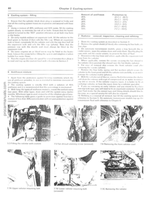 61
61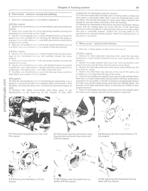 62
62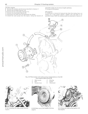 63
63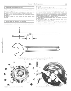 64
64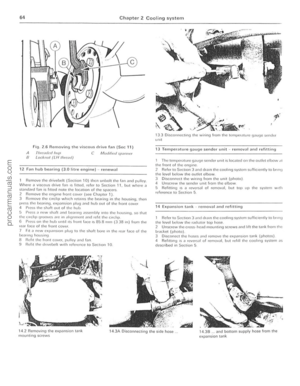 65
65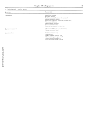 66
66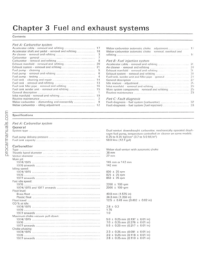 67
67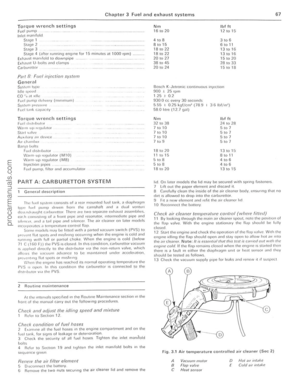 68
68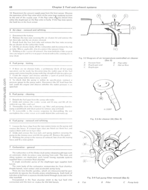 69
69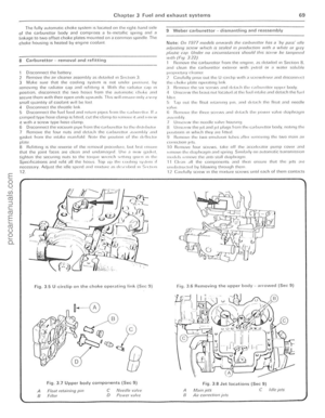 70
70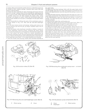 71
71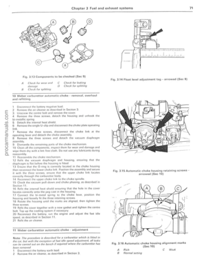 72
72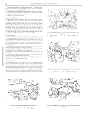 73
73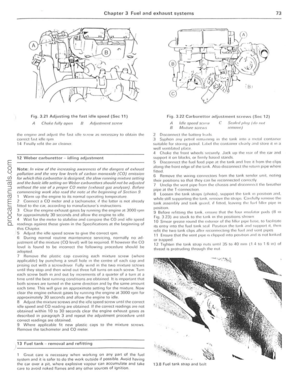 74
74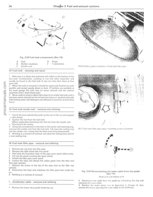 75
75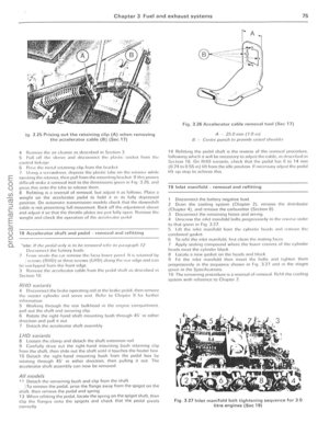 76
76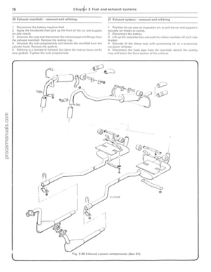 77
77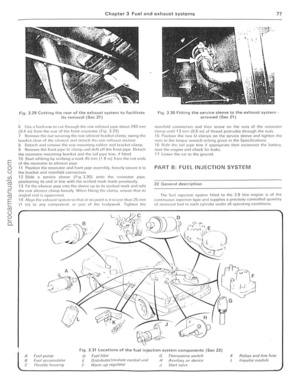 78
78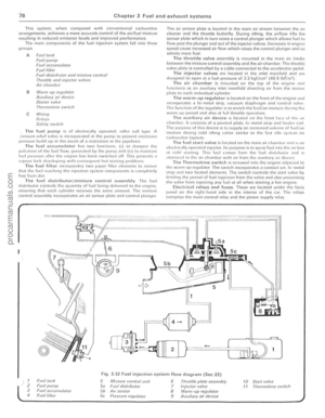 79
79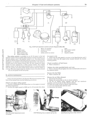 80
80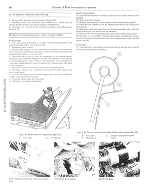 81
81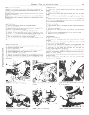 82
82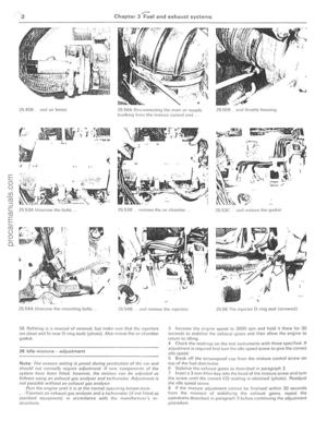 83
83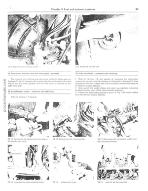 84
84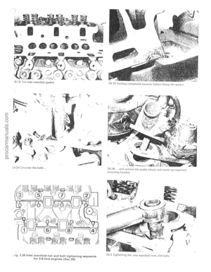 85
85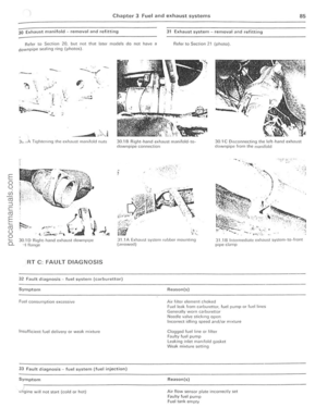 86
86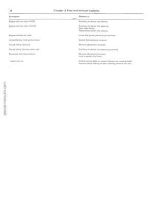 87
87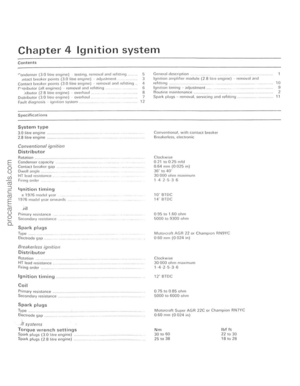 88
88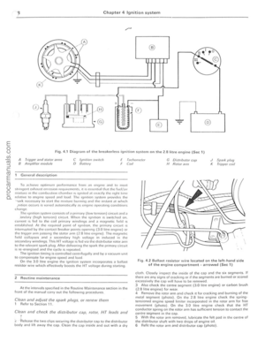 89
89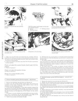 90
90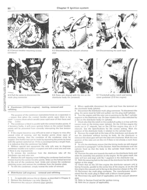 91
91 92
92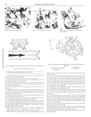 93
93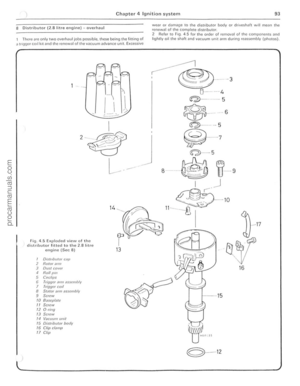 94
94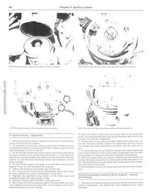 95
95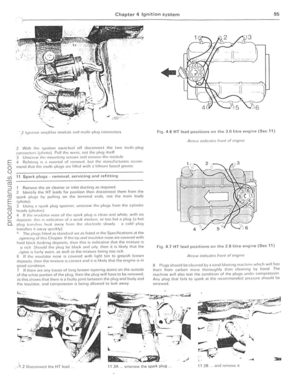 96
96 97
97 98
98 99
99 100
100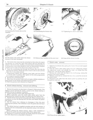 101
101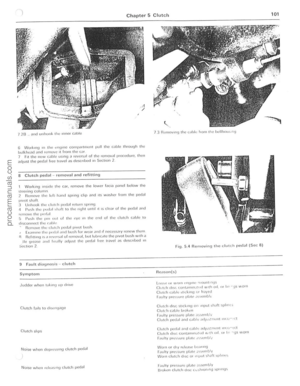 102
102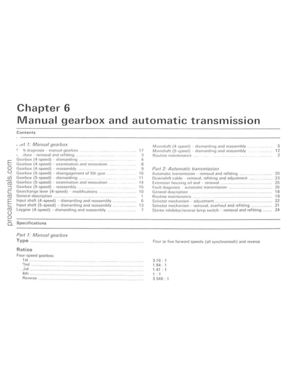 103
103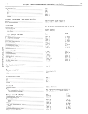 104
104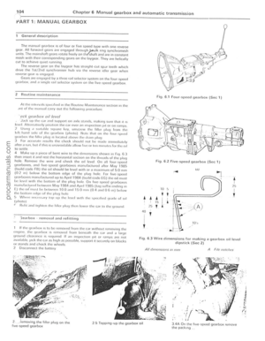 105
105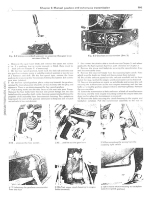 106
106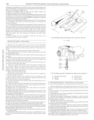 107
107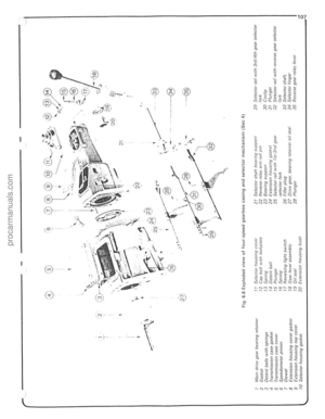 108
108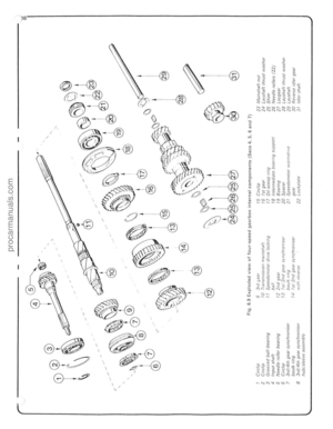 109
109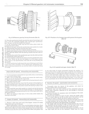 110
110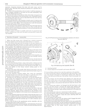 111
111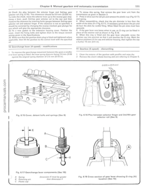 112
112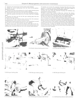 113
113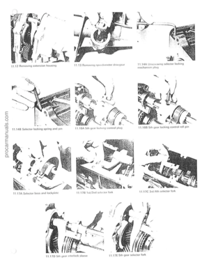 114
114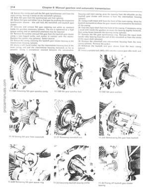 115
115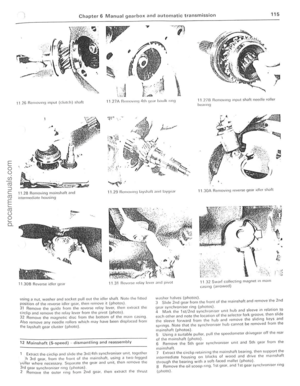 116
116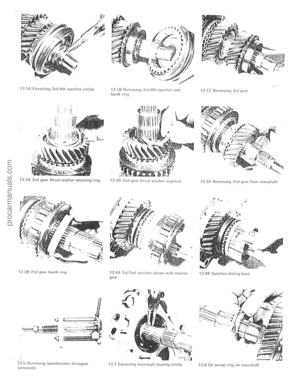 117
117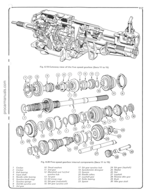 118
118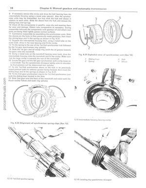 119
119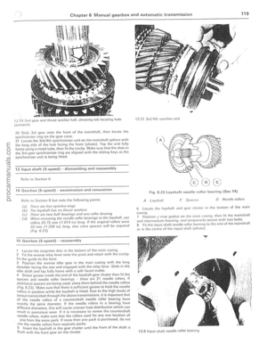 120
120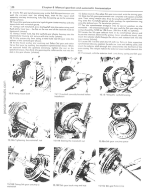 121
121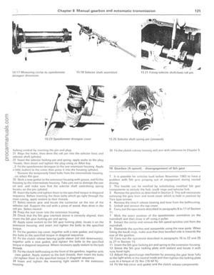 122
122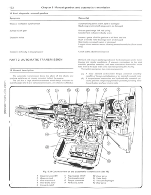 123
123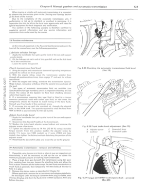 124
124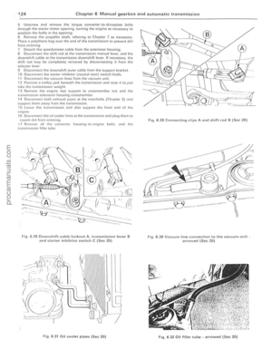 125
125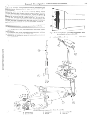 126
126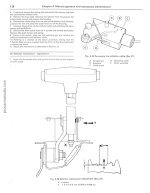 127
127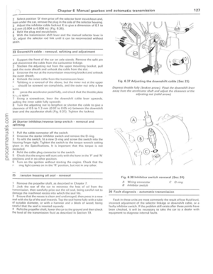 128
128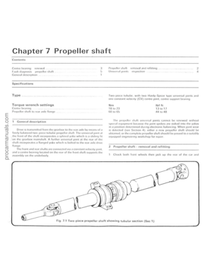 129
129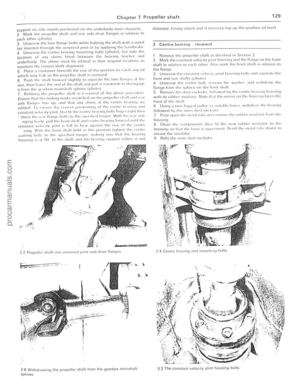 130
130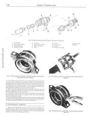 131
131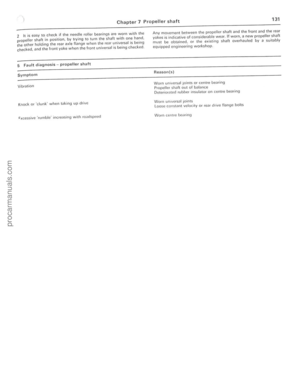 132
132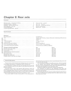 133
133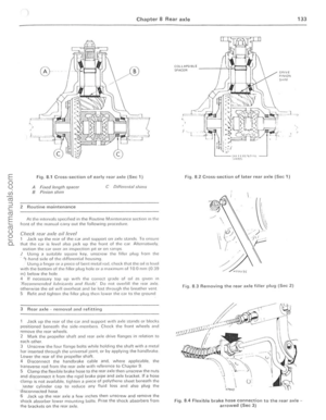 134
134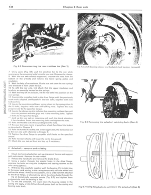 135
135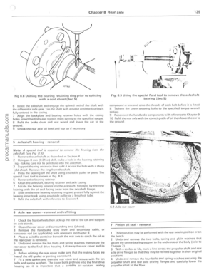 136
136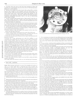 137
137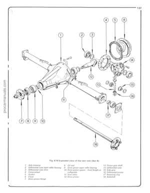 138
138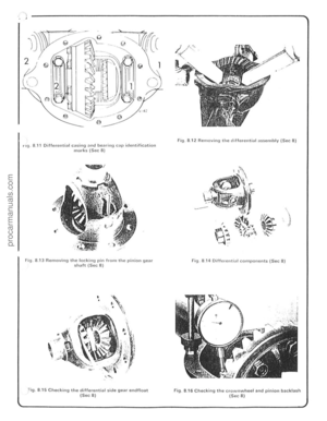 139
139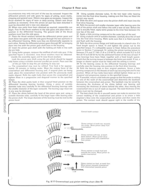 140
140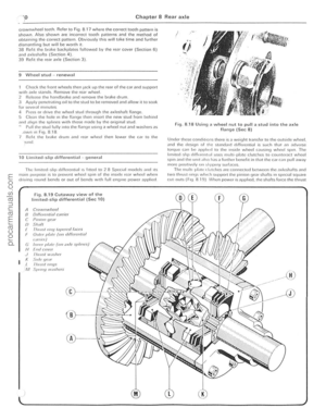 141
141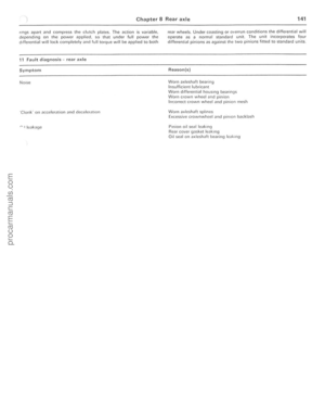 142
142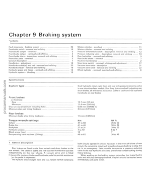 143
143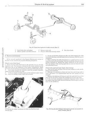 144
144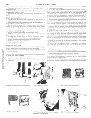 145
145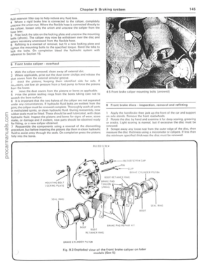 146
146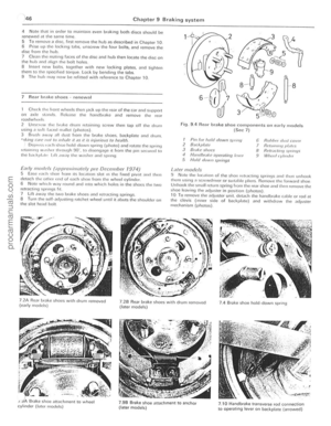 147
147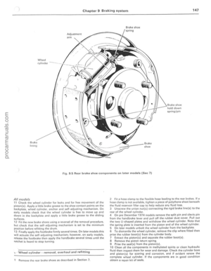 148
148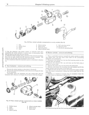 149
149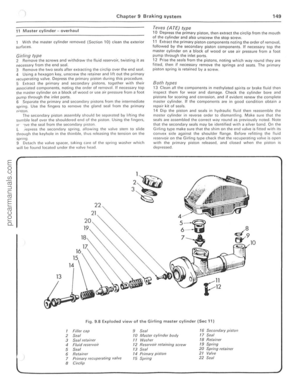 150
150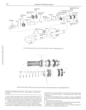 151
151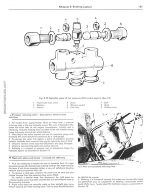 152
152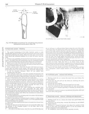 153
153 154
154 155
155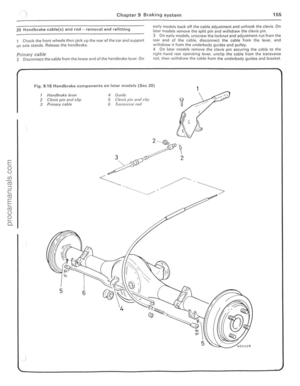 156
156 157
157 158
158 159
159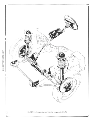 160
160 161
161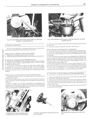 162
162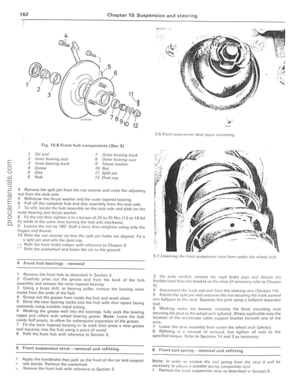 163
163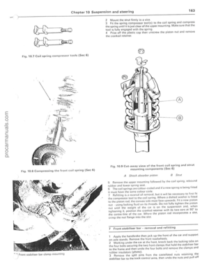 164
164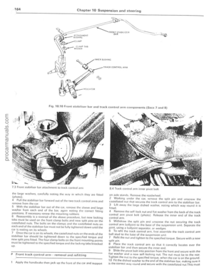 165
165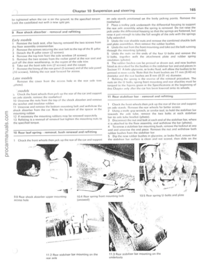 166
166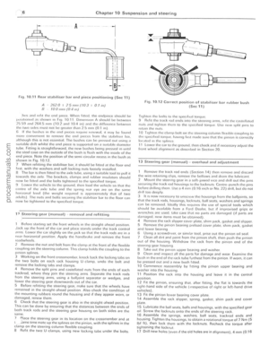 167
167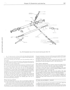 168
168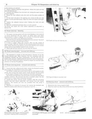 169
169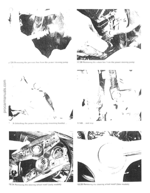 170
170 171
171 172
172 173
173 174
174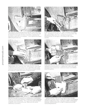 175
175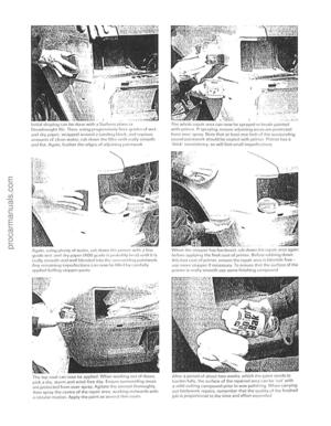 176
176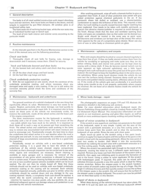 177
177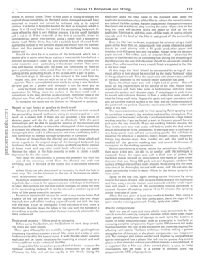 178
178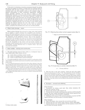 179
179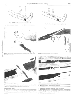 180
180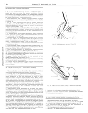 181
181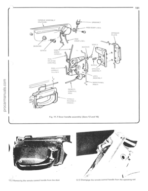 182
182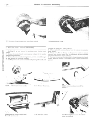 183
183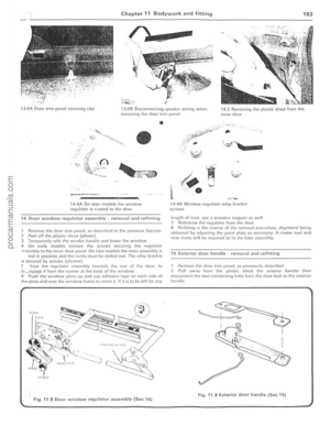 184
184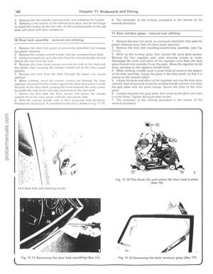 185
185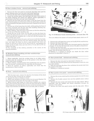 186
186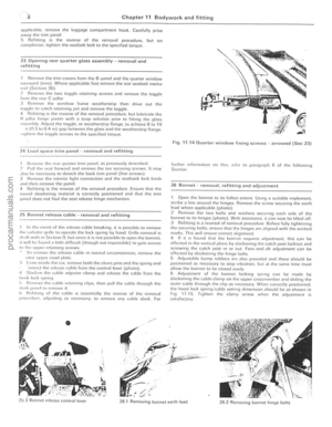 187
187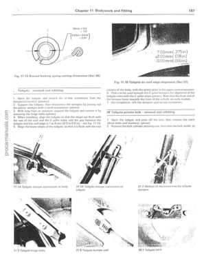 188
188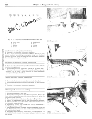 189
189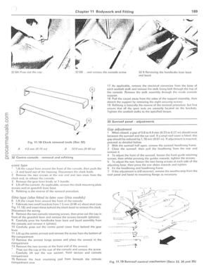 190
190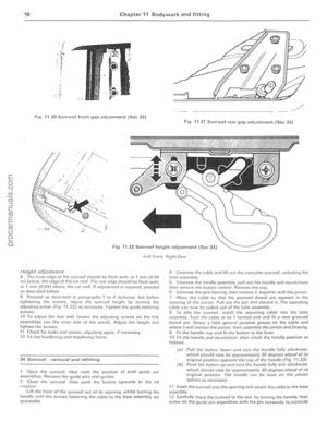 191
191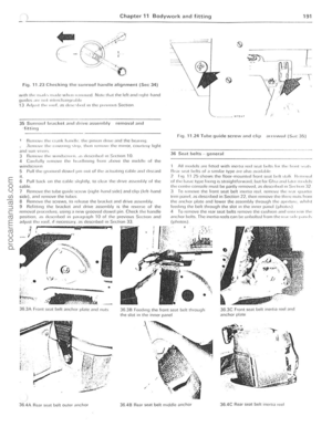 192
192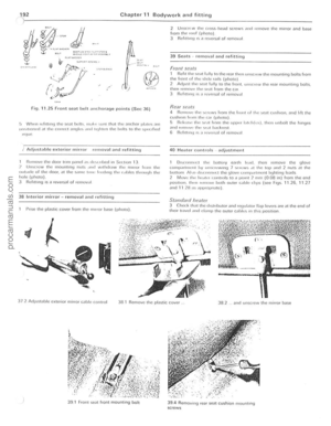 193
193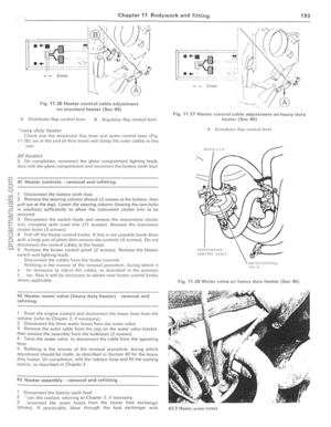 194
194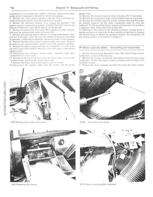 195
195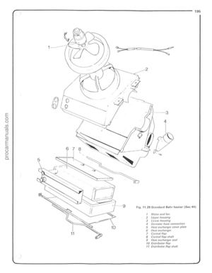 196
196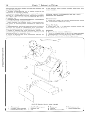 197
197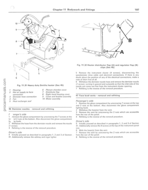 198
198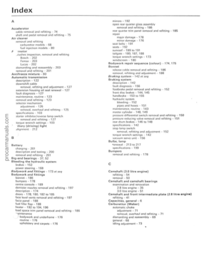 199
199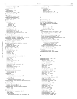 200
200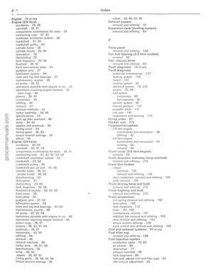 201
201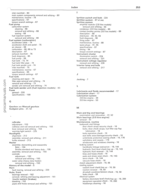 202
202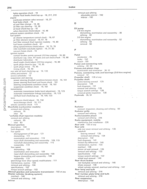 203
203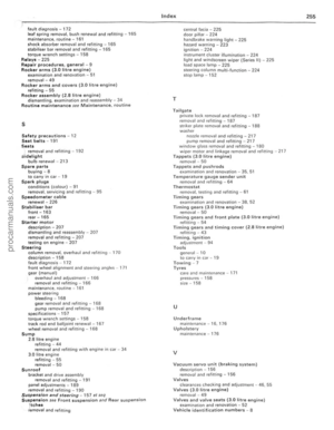 204
204