Page 73 of 205

72 Chapter 3 Fuel and exhaust systems
3 Unsc.cw the cenlle bolt and .emovc the cove •. T o p
VtlCllllm pul/-down 6 FII
Choke phasillg 7 Hold tho Ih'O Hlo 1),1.tly open
IJ(mdlllU Ihe tau. S Rn"t Ihe intelnal hcal stueld eIlS''''"\1 Ih,lt Ihl! hole ,n the COve'
locmes COrfeclly 01110 Ihe t :le\] CkOt. and t'yhten the C"n\'1) bolt. Top up I he coohng s y Slem ,I Ilccess: llY 12 Reconnect!hc h;")lle'y . run thc ell!l'"c :",d Mllu~t Ihe 1,IStldle spccd ;,s d"sCllhed III Ihe 101l0winU Pil';'!I.;lph
Filsl idlv speL'd 1 3 hlc;IlIy" tachomcte. wlIII,c .eq,,"ed !lllmlc. 10 sellhu t,'~1111l1! 'P'" 10 lhe ~peclllncl v.1Iuc . nUll lhc CnnUlc lip to no.,,,al opc.at"I!1 t,:'Upe."lu,e. then ~wO\ch oil ;Jml COllllect Ihn tachomete. (whe.e .wn"a"h,) OpCl1t he Iluollie pal\lally. hnhllhc chokc pl.1\(.)5 lully closed tI'"" 'ele,lse tht.! th,ollie $0 Ih.111he cho~e 1""ch.1111$I11 IS held 'n the fast "II" fK151\10" Relc"$c the cho~1"l pl.ltCS . d" . .:ckllll! lh;lllhcy .cmaln lully olwn (II they ".c not open. Ihe ,lsse rnlJly IS I"ully 01 Ihe cnU"lc ' S 1101 al 01Ie .,11111IJ len'I/C,,'lurc) Wlthoul louchl"H the ;lc c"le."to. ved"I. Sliltl
, ,
~A
Fig. 3.1 9 Choke phasing adjuSlme'lI (Sec 11)
A 0,,/1 8 AUjus/my'"y
Fig. 3 .17 Checking the Vllc .. "m pull·down with l' drill {Scc 111
A t:lils/lc Im",' C V;//:1I11111 ('I'~'f,~lmllull B DIJII
Fig. 3.18 AdjtlslinU the vacullm pull- down (Sec 11)
A 8
Fig. 3 .20 linkage SCI fo r checking fast idle adjustment (Secl1)
procarmanuals.com
Page 74 of 205

A Clloke f(llly Olwn ()
the 1:1l!)1I1\" alld ;HI)\"~;1 lhe lasl ,die s<:rew as llecess;uy 10 ohlain lhe COlle")
Chapter 3 Fuel and exhaust systems 73
Fig 3.21 Adjusting the fast idle speed (Sec 11)
A Clloke f(llly Olwn ()
the 1:1l!)1I1" alld ;HI)"~;1 lhe lasl ,die s<:rew as llecess;uy 10 ohlain lhe COlleCI la~l I(llf~ 'Ilill 11 Finally felll lhe ,\(I cif,.1ne,.
1 2 Weber carburettor ~ id lilllJ ndjustment
N ote: III view of lfoe illcfem;illg ,1WmeIJeSS ollile d,lI/flefS of exh.lflsl pol/ulioll olml Ihe vefY low levels of cmbol! //Ionuxirle (CO) emission fOI which Ihis e,,,burel/o, is dcsiW!N/. IIIe: slow fUnlling mix/ute: se:l/ill9 ,wd tin' b,lsie idle svlling all WCbt'f e,ltborcl/OfS shoufllllu/lw "djus/cd Wililoll! OW (ISO of a {!fop!"!, CO flfv/ef (c·Xll,lOS! fI"s iflf'lfyser). Bdum CUfluHencillY work ,1150 f(;o1(/ /he flO/t' .11 til<: IW9innilly of Sl'CltOn 9 1 Walm LIp lh(l (ll1gU)(l 10 ilS nounal operalinu If:l1lpCrailH(l 2 COlIIlCCl .1 CO nleler ilnd " lolchol1l(llel. ,I lhe Iilller ,s nOl aireCilllons .11 lhe IJCU>flninu 01 tillS Ch,lplN . 5 Adlust the Idle speed scrcw 10 give the COIfCCt rpm. (j DlHlllO nornlnl rout>nc m~>lltcnnIlCC serv'CIfl!I. norll1<1lly no ,1d·
IUSlrnent of lho mixture (CO levol) w,lIb(l requll(ld. It howevel the CO levcl is lound to be II1COHCCt thc 10110willII p locedwe should be ,ulnp!Cd 7 Rcmove lhe plast,c Cn(1 In lhe two nllxtwe SClCWS lInlil thcy stop 111ld lhc n wi"d Olll lhwe full turns on e~ch sClew. Tum e.1ch screw both III
cl1ch ll1ne. This wllf give nn l1pproxirnntl} St:ltinU lor lhc rlllxlure. Now clC.1r thl} cnginc cxhiltiSl g<1ses by IlInnmu the enUlne ~1 3000 rpm lor ilpproximJtcly 30 scconds !
corr(lCl readings me ohwined. 9 Whe,e applicable f it new plas tic cnps 10 the mixture sc,ews. Remove th(l taChOmeler .1nd CO meter.
)13 Fuel tilnk ~ removill .lIld re fittin g
Gn;at cs n~ccssary when wOlkmg on 3"y parI 0 1 th(l luel system
FiB . 3.22 C
A fI /dlc Spt'cil SC".,V MHIIIII.' SCII.'WS
2 O,sr.onnuct tho !Jallf)ry I,·"ds
c S,.',l/,·" /J/IIY rd,) ,wI lemow.')
3 Syphon o1"y petlOl Ii,,,,a"u!)!) III Ihl"! t,lnk min a 1",,1<11 conwu'"r sUltiawd plar.e 1 Choke lhe trolll whe"ls S"culI~ty Jack up lhe Ie"" 01 lhl"! CM ~nd ~;IJPpOfl II on htocks. or Il(mty h;'~(ld slnnds. 5 DlsCO""ccI1he luet leerl p>pe <11 Ihe lank and III,e 11 from the clips alonu lhc IIOnl edge 01 the liwk. AI~o (hsco"ncct the return pipe where litted. G Remove thc WIfIIlO conneCl0,S 1 10m lhe tnnk sllnder til"!. nOllllg lheir pOSlllon$ so lhs ,md dI Sr.Olllll"!t:t the lJr();\lher pipe ~t lh(l T ·COlloccllon 8 Loose" the t.1nk shaps (pholo). ~"ppo'l the 1;II,k Ul pos,t"m and. whole slin suppOlll"'I the tilllk. "'IllOVC lhe Strill'" C"rf)lully WIlHlve ltll, lo1nk .1%clllbly ilnd i,,"k \lLI ;IId. 11 lolled . leilv>lI\I II", r",·1 I ,ll", pipe I" posit>on. [) Belooe rel'lllll!) tlill lallk. (lIlSIlIC 110011 lho ftHIl "'sut,lItH p"d~ (B "I FlU. 3 23) nle sluck 10 Ih" lank III lhc pOS'I>OIIS shown 10 Smea( Ilrease IOlind lhe exlerlor IJllhe 1011,,( pqw h,,~e. to I"c,hlate liS ent ry >IllO the fUl;l lo1nk se;,1 1'0"lllon the lallk ;IIld ~lIppl)<1 ,1. tl"", relll the twO (Dilk dips i,Itl:l rc,:onnf)i:lul(l the lu,,1 ilnd vCIll p'pcs 11 Ensure t.llJl lhe vent p>pc 's cirpp"d 11110 po~,>l,on ,'!HI IS nOl klllked or u.1pped 12 Tlulotcn the tJnk stlap nulS lInnl 35 to 110 ,HIll {I ' 10 1 (j Ill) 01 lh,end IS prOlrudlilU lhrouuh the nlll
~.* ..... ·0 ~'.~',":L: :~ .. ~" :".~ r~r· .. '.~ . . ' . -
.... ', . ~ , . .
iil~);-< .~:a
1 3 .8 F uel tank StrllP lInd 1!OIt
procarmanuals.com
Page 75 of 205
>
,
Fig. 3 .23 F el <ll1k coml> onenlS (Sec 13)
A
\" C
Se.ll Ruhbcl ill,W/,lIQI S SI!IIIJ..f lIoil
14 Fuel lank -cronning DrHI rcpl1ir
D SImps")
74 Chapter 3 Fuel and exhaust systems
, ;
1)'>
,
Fig. 3 .23 F el ' onenlS (Sec 13)
A
" C
Se.ll Ruhbcl ill,W/,lIQI S SI!IIIJ..'f lIoil
14 Fuel lank -cronning DrHI rcpl1ir
D SImps E , COllflcetiu"
W,lh IlI1m 11 I~ likely Ihal scd'lllcnl .... .11 COIiC(;1 1f1 the IJOIiUlIl u l the ruel wnk. Con
15 Fuct lank sender unil _ remov;11 nlld refilliny
Check Ihe h01l1 whL'{)ls Ihen J;lc k ufllhe le;lr of Ihe 17;11 ;'Ind supporl ,1 ilxle sr,llids . 2 SYI/hon Ihe fllel hom Ih e tllcllim k. Wherc ;lpphcilhle d,scol,,'ecl Ihe fuel line hOIll the scnder unll.
" Discormoci Ihe wiring 5 USlllljlWO SC!(lw(i!lvers III Ihe 51015 inlhe sendcr unit ,e lirmlng 1111\1. unsr;'ew Ih o sender (mil loom Ihe tucllilnk Lilt ilW;lY Ihe scaling ling iln d Ihe sender unit. nO llng Ihill Ihe 110.11 must hilng downw;'IrrJs. G Re fill ing is a rever snl of .e moval . bUI clea n lile milling !;lces ;'Inel I II ;'I new sealing ring .
1 6
Fuel lank filler pipe -removal "nel refitting
I Remove the cap horn Ihe hiler pipe. 2 Re movo Ihe .ighl·twnd siele lIim p;'lllei. 3 Peel back Ih e in sul alion clear 0 1 Ih e pipe (:Over fliln cl (Ghia only). 4 Lift outlhe pimel coverinU Ihe spore wheel. 5 Unbolt Ihe IllIer pipe covor panel. 6 Lo osen th e clips and releilse Ihe rubl>C1 oail er from Ih e floor and f,llel pipo (phOIO) 7 Remove Ihe screw al Ihe lO P of Ih e pipo nexl 10 Iho filter cap (photo). 8 Disconnect the hoso and withdra w the I.ller pipe I rom in si de Ih e
car.
o Relill ing
is a rever sal 01 romov;lI,
A
cceleralor cabl o - removal and relining
Removo Ihe
lowe. lac.a panel inSide Ihe ca'.
166 Rull"'" !F"1I1';'I1 "otlom " I I"". la llk flU", l"llll
(
. ,'l
--.
. ~
1(; 7 Fuel lank flUc. Pll~ UppCI 1II0UIIIIII\I SClew (.lIwwL't I)
"
, I;'.' . :~, \;.;
: : i;. "j -' , ,' .... :r: , :'y~ it. ; '., :
Fig. 3.24 Disconnecling Ihe innor cabla from the pedal (Sec17)
Pusll M 11 ,mrl rcfc,uc ill IJ
2 Disconn(:cI Ihe cahle 1<0111 Ihe I)OOal hy unhookoug Ihe clip and rcleasing Ihe ""II:! cal,le 3 Rem oye Ihe IHal:.e servo un:1 a~ dcscfLb c(1 11 Ch;lll lcr 9. Ihen remove the SClew securrn~J Ih(: Oulcr cable to Ihe iJulkhc;'ld
-
procarmanuals.com
Page 76 of 205
![FORD CAPRI 1974 Workshop Manual )
Chapter 3 Fuel and exhaust systems 75
;\1.325 Prisillll oul tho re l<lin in\] clip (A) when removing IIIH acceluralOr callie (n) (Sec 1 7 )
~ fl""",V<: Ilw au eli!.",u. ;IS d .. ,~r."'J(](/manual-img/11/56932/w960_56932-75.png "FORD CAPRI 1974 Workshop Manual )
Chapter 3 Fuel and exhaust systems 75
;\1.325 Prisillll oul tho re l<lin in\] clip (A) when removing IIIH acceluralOr callie (n) (Sec 1 7 )
~ fl\"\"\",V<: Ilw au eli!.\",u. ;IS d .. ,~r.\"'J(")
)
Chapter 3 Fuel and exhaust systems 75
;\1.325 Prisillll oul tho re l
~ fl""",V<: Ilw au eli!.",u. ;IS d .. ,~r."'J(:d III Sf·etlan 3 5 1',,11 011 tlo" ~I""VH ,,,HI d,s<:OlUI'!Cl 111" I""~II<: sock", 110m 110"
cOlll,,,1 IIIIK"!I" G I'll'." Ih" ",,,,,,1 '''','UHrI!l <:lIp hom the IlIi,,;k"l 7 U~"'!I a ~,:",wd"v"r. d"I"CSS tile pl
111 Accelerato r Sl,,'fl and ped,, ' -rc "'ov;,1 ;,nd relilti"u
'o le: If /I" ., IU:(/"I ",!ly ,.~ to "(~ /f.'/!/oVI:1I /("1,:, (0 1""""1';'1"" 12 [)I~.,:,,,,,,,'cl (h" 1",lle,y lea(ls ? r",," liNd" t lw C,II lemove Ihe 1;)(;';1 It""", 1';,,,,,1 II I, '''WII\l:d hy ,,<'I(:W~ (IlHO) OIII""e S{;WWS (LHD) "IIIII!I Ihe ''',II "dUI! ami C;1Il tJ" IUH:lopp"d l,ulll lhe hont l~d\)c 3 n"lllove th" ,u;cole'''lot cilhlc hom Ihe p"dal sha h olS ((e~""h"d III
Secll"" 113
RI-IO variilnls 4 DI~(u"ncct Ihe IHake ope',IiIl1\J IOd ill Ihe b'ake ped;rl. thcn 'enluve tio" I"aslcr cylinder ,lilt! sc,vo lllHI nell" to Ch,lpl!!' 9 101 lUll lol'l
'nl')lll1alI1111
5 WO,kllll) I I"OIl\)h (he ,e,l' bulkhead III the C "IJ"'C vo"'p,"t""!1I1. pull Ollt lire sh;rft "nd S"CUI1I1() chp () Rotate Ihe I1\)ht·h,,,,d Shil l I IIIO'"ltlll\) bush Ih,ou\)h 45' ,n e'lhe' d1lCC1l011 ;)nd pull II Out 7 DetaCh Ihe
LHD vmi,!IIls 8 Loosen Ill" clamp illHI dewch Ihe sh;rlt exlClls,on ,oct. 9 C;uefully rlllve Out the ,,\)Ilt·hand 1110unlll\\) bush 'ewln, n\) clop 110111 Ihe sh;)h, thcn slide Out Ihe sh;)h ulll,1 ,t louches the hCitlC! IJOx 10 Detach thc "U1l1 h,H\d mount'n\) bush I,om thc ped;)1 1J0~ by 'Olilllll\) tlHolIUh 4 5' 11 ellhe, ducctlon, (hen pulhng It oul The ilccelera!{), slHlit [l5seml;l), Cilll 'lOW be removed
AI/models 11 Oetach II", 'em;lIl\ll\Y bush ;rm] clIp hOIll lire shalt. ) To re11l0V" the pedill, pl1se the f!;ln\Je ilway Irom the SPIYO( on lire snail. lhell ,emove the p"dal and sp"ng 13 WI,en ,eflll"'!! tire pedal. locilte the sp''''U on Ihe SPIUOI shall, lilr,, clop th" 11""\)"$ 01110 Ihe SP'\JOIS ilnt! check lhilt Ihe pcd;)1 I"vots
cO"lIetl),
Fig. 3.26 Accele ra to r cable rc moval 1001 (Sec 1 7 )
A _ 250",,,,(10,,,)
() ~ Cell(fe IlUlidl /11 /J!Uv;d" ',1,SL'd -'''ullld ... ,
14 ncllll"'() the pud.ll shilft ,s Ihe ,eve,su 01 Ihc lelllov,,1 IHocerhllC, lolinwlllU whIch It w ,lI he 'H!CUssa,y to ;ullllS I It,,) cailic. "5 d"scllt)IJ d 11 Si,(.t'OIl 16 OIL Rill) v;",allts. dlcck lh;ot the I)(:d;oll"'$ 6 tn 14 ",m (02" 1{) 0 55 'Il) I,ft 110'" the nflu posit 'on If IIo,,"ss.u y ild)"st Ih!! pedal
Iofl up ~!Op !O ach'"ve I h,s
19 1"lc t Ill[l"il o ld -rClllov;l1 ilnd rcfitting
1 DIsconnect (he biltlc,y ne(),1Ilve IUild. 2 D'illli Ihe coolm\) syslem (Chapter 2). ,emovc Ihe d'StllIJU1{)I (Chapl", 4), and remove the C.llilll'et!O' (SectIon 8) ] DI~<:OIlI,,:ct til!! rl!m,IIIiUlI) hoses ;rlld Willi'\) <1 UllSV,P.W the 'nlet m;r,ulold holl~ p'ouress,vd), III II", ",v,,'~r: oldl)I 10 that lflvell II, 1"1) 327 5 LIft 11'1) II,let Ill;H"lold frum tlH! o:yhlHit;, hr:;lds ;",(1 II''''10(:k 8 LUCil(e il lIew \)Jsk\lI Oil lh" Il(lild~ ;",(( block :J Fll the Ullet '11;UlIlo ld then II'S"II II,e holts olml i<\)ir(ell them 11Iou,ess lvcly ,n Ihe scqllencu shown In F,U 327 alld ,n lire sw\)es
\)IVCll '" the Spec,fr~.lt'ons 10 The '''lllillll'''\) proced",e IS" 'eve,s,,1 01 ,elHoval rlefrlllhc cool",'J s)'stem WIth Icfe'cnce 10 CI"lpte, 2
Fig. 3.27 Inlet III,mifold bolt tightening sequcnce fo r 3.0 litre engines (Sec 19)
procarmanuals.com
Page 77 of 205
,li<.e then lilCi<. up Ihe Iront o[ Ihe Cill ilnd")
76 Chap~r 3 Fuel and exhaust syste m s
20 E~huust nlllnifold -removalllnd refitting
1 Disconnect the hallelY negillive h}ild. 2 Apply the h,lndl,)',li<.e then lilCi<. up Ihe Iront o[ Ihe Cill ilnd suppo,t on axle stands 3 Unsc,ew the nulS ilnd d,scontlect th c exh;!ust pipe alld U;lIl!) C 110m Ihe edl;!ust tIIiln"old. Rctllove the sc;!hnH tlllt!. 4 Unsc.ew the nulS p,ou,ess,vcly ;!lIff ,cmove the tIIOlrllfold from IhC
cy lrnd c. heOlct. Removc Ihe gaskels . 5 Refrllrnn IS;! Icvers;! 1 01 renIOV;!!, hUI cleOllllhe millrnlJ 1,1COS "rul Irl new n,1$kClS Tr\Jhlon Iho nuts prowossrvoly
_.-/-
-'
1
2 1 E~rH1usl s ystem -removul ilnd refitting
Posi ,ion Ihe COl' ovcr;!n in~pcction I)rl. O. 100ci<. ,hc CM Hnd suppa., II securely on blocks o. stands. 2 DrsconnC CI Iho bllttcry. 3 lrfl up the rosonmo. hox ;!nc! pull the ,ubbe, rtlsulato. off each srd e b,;!ckel. 1 50111",1IC ,111 Ihe Clmlll) nutS wrlh p<:nClfmrng all. or II jl'OPtlCI,',y
COfl05,on inillbrto • . 5 Disconn ect lhc f!Onl pipe f,om ,he milltlroid. d e tilr.h the sOOlhnu lin!] and lower the ,.onl section 01 ,he lIxhaust
F ig .
3.28 Exhaust system coml)onetllS (Sec 21 )
procarmanuals.com
Page 78 of 205

6 Usu a hadsa w 10 CII I II\"Ul!lh Ihe .e:!. Cxh:!ust ppe ilhoul 240 mm")
-
Chapter 3 Fuel and exhaust systems 77
Fig. 3.29 CUlling the reM o f tho exhaust system to facilitate its removal (Sec 21 )
6 Usu a hadsa w 10 CII I II"Ul'!lh Ihe .e:!. Cxh:!ust p'pe ilhoul 240 mm (94 .n) ItOm Iho! ''';]' ollho I.onl tI:S(HlilIO' (r.O 329) 7 Removtlihe IHII sl:(:IIIIIl!llhe I.:a. sllrm cm hlolt:kel clamp. SWU1!llhc hl"ck,,1 ell,;" ot 1111, sol"nc", :tni! ,,",I ,lcll lit" ",n, e xhausl ~(,CII"n. 8 Ot.lt.1Ch ,1", 11"'110VI) Iho I"a. IIIOUnlll'!IIIIIIlw. :tnd IIIa(.k,,1 clallip 9 Rell1uve Iho hont P'P" LJ r:lallip and dill I oH 1111) Iron I pipe . D"t;tcll Ihe f(:sonn lo' 1I100mlll'!! h.ack", and Ih" wll plpt: 111111. If filled 10 Slilll 1e!11!1Il!j hy SCllhlll\j il nlo"k 115 I'"'' (1 8 III) 1,0m Ih', CIII ends ollhe ,csonnto. 10 Silence. pipe I I POSition Ihc .csonnlOl and ltont II'IX! ilSS(lmhly. loosely SUCIIIC ,110 the hr,'CkC I and man,Iold connCCIoOIi 12 Slide a se.vice sleeve (FlU. 3.30) 01110 Ihe .eson ;IIOf I"I)C. pos,"on,nu lI S end In Ime with Ihe s O lhed ma.k m,llle p.eviously. 13 F'llhe Silence. l)lpe mlO Ihe sleeve up 10 lI S sCli hed ma.k and .ehl Ihe .e:!. StiOIlCt" c l."up ItJo~ly Wilcil hlhll!llhe clamp. ensutc Ihm liS
;IIlUlet! end .s IIpp • .:tlnn~1 111 1\l1!II'lhe I!xhatls l syst"m sn Ih;11 .. I tin 1IOilit IS 'I Ile;u,,' Ih;)l 1 25 "'''' (1 III) 10 "lty i:Oll'pOllelll. o. 1',111 01 Ihe t,,,dywn,k TI!lilteli th\)
• J. ,
.) '. ,
FiU . 3.30 F itting the service sleeve to Ihe eKhausl system -arrowod (Sec 21)
II1n n llol(1 conn(:(:tlon and Ihen screw on Ihe nUlS of Ihe .esonnIO' clnlllflllll111 13 mm (0. 5 m) of Ih.end Pfotrudes Ih,ough Ihe nulS. 15 1'0SIlion Ihe IWO U·dmllps on Iho service steeve and li!Jhlen the n\llS 10 thu IO'IIIHl w.ench sc1ttng Uiven in lite SPCClhC,ltions 1 G [1"" 1 lit,) 1;111 pIpe 111m of "pP'OP".1W thon reconnect Ihe b.ll\e'y. M:ttllhe OllOine and chock 10' 10,lk 5 17 Low,,, the c," 10 Ihe Wound.
PART B, FUEL INJECTION SYSTEM
22 Goneril! description
The 111,,1 "'1"Cllon sySlem fitted 10 Ihe 2 .8 hIre engIne IS o f the COllltlllHlIlS '''IL'Cllon Iype ;tnd sttppltes " p.ecisely conuolled (IUnllllly (II ;I\()lII,":d hll:1 10 "nch c ylt1lde. undo. fill Ollo.nttng condItions.
A U C
Fllel plllllJl FII~·1.1C'·''''IUI •• tul '''mUIr) IWlls",!}
Fi g.
D f F
3.31 Locations o f the fuel illjection system compo non IS
Fuel "'WI G rhemlolime switch
(Sec 22)
K
L Relays ilnd line (lise Im,lu'se module OrstllbulQr/mixture cO/wol "",I W,l. m·up leguliltol H Allxrfi,lfV illf device J Stilll valve
procarmanuals.com
Page 79 of 205

,
. ,
I , ~. !
78 Chapter 3 FlIer and exhaust systems
TIlls system, when comp1lrcd with conventlon,lI c.Jrhwctlo, ~rrilngemen1s. oncms of tho fuel inrcclton system lall into three
tI'(lllPS
A FI/ef Milk Fuef Plllllf! F/lel .?CCIIIIW/<1IOI Fuel filler F/lel ,IISltihular ,w(/ millime con/rol l11ralllc MIlllll/ce/Of "',1/1'115 AI( ch.ll11/"1(
B W
C Wilil/[I Hd,.ys SMt'ly SWitch
The fuel pump IS 0 1 eh,CIIICtllly operated. ,aile. cell Iyp" A .",SS (IIC rchd ..,:,1..,0 'S mco,p[)I;oh~(1 III the pwnp 10 preY",l! f:XCOSSlvn
p"'SSUIC la"ld III) '" tho event of ,1 ,,)Sl"Ctlon III th e pipelollf!s The fuel ,I(:c\llllula lor ha~ 'wo lunf.luItlS. (t) In 4'ill1I,)(:I1 llll! IIIII,,;,'U)!l 0 1 lhe luclllow. HHlu.:.iI ,ml hy Ihe I)\I"'P ;IIIf' (II) 10 11I;""t,"" Iud I"'"'~''''' ,,1";1 .h" .:o,!.m" h;os Iom,n sw"dn,,' "If TillS p.r.v"rlls .• v; 'po", IIH:1o; .lo.:vel"I'III!1 w,th t:'Hlf.O:'I""nt 100' ~t,'
OIlS""l1g .h'lI each cylrndo. fCCOlves Ihe same ;lII1OtUlI. TIlt! mlxhlW COIII.ol aSSemhly ,ncorpo'illes ,III IIi, senso. pl, 1le ;m d cOlllml plllll(le •.
6
9
The iI" sen~or 1)1"le is locilled in 'he main nIl Stlealll be.ween the iI'r clr:wller ,1nd the Ih'Ol\Io bullerfly. Du'ing idling. the ~irflow hits Ihe sensor plate which in tu.n '
Fig. 3.32 Fue' injOCliOrl system flow diagralll (Soc 22)
1 Flle/lall/(
"
Mu;/ulc CUIIIIOI ,mif 6 IIIIOlfic pla/c assembly 10 S/;II/ villve 2 Fuel PIIII/I' 5., Fucl (Iistllbutor 7 Inicc/or valvc /I 'hell1JOlimc sw,lch 3 Fuel i'CC/IIIIUI"tul 50 Alf SCIISOI 8 WiJllII·Up regula/or 4 Fuel '"10:1
"'
Plcssule regtllillQI 9 AU~IIt"aIY air device
·.i
<+
procarmanuals.com
Page 80 of 205

Chapte r 3 Fu el an d exhau st systems 79
Ii
0) G
\E )
.. ~ ee)
Fig. 3.33 Fuel injuctiOIl system circuit di<lUrnrn (Sec 22)
1 /J,1I1C 1V C W\"lflll (If! luyu/,lor plMC
2 Sialicr I/Iolor /)")
)
Chapte r 3 Fu el an d exhau st systems 79
Ii
0) G
\E )
' .. ~ ee)
Fig. 3.33 Fuel injuctiOIl system circuit di
1 /J,1I1C 1V C W"lflll (If! luyu/',lor plMC
2 Sialicr I/Iolor /) Axll/,-"y ,1i, device G Theo1lO/lmc switch
3 fgnitioll switch E FIII;I/Iump H St,lfl valve
A M,lin con(Iol r(;/,)y F S
8 Power supply rcl.1Y
Tho safety switch is provided to cut olf illl power !O the fuel injection sySl(!m if the air sensor plJIC (mixt\HC COlllrol assemhly) IS il the rest position even if the ignition switch IS all. The s[lfcly switch would ell! off the power to the fuel pump for oillllpic ,I il fllOJllmu W
23 Aoutino maintenance
AI the IntelV
Check (Jnd adiusl idfing spoed 1 COllnecl11 11Ichomeler to Iho engine then rlJll the enVine to 110rmal Oper
., '
,. ,
< '(:,,~ , • . . ;::~t,·· . , ,
.' ) . ;~ ~~;:;: ~iJ" .. ,
n fr.X l
the engllle 10 'die.
3 Check Ihill I he idle speed is lIS given in the Specificmions ilnd il nccnssary "dlust the idle speed screw 10cllted heneillh Ihe Ihrottle housinv {photo).
Check conditiorl o f fuel hoses " Reier to SeClion 2.
Tighte/l the inlel manifold boilS and /luis 5 Refur 10 Section 29 and lighten the inlel rll
Reflew Ihe fuel filter 6 Refel to Sec tion 25.
Renew the air filter element 7 Disconnect the h
assembly, ,1rld hit out the air filler element {photo). 10 Cle
23.3 Idle speed ildjustrnellt sc rew (arrowed) 238 Releasing the .. II cleane l spring Clip 23.9 Removing t he air filter element
-
I',
I t, ' .
;
!
" , ' .• I
! 1 I'
: 1'1 1 . ,
I
I '
I
procarmanuals.com
 1
1 2
2 3
3 4
4 5
5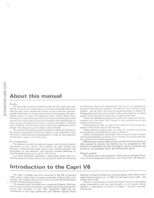 6
6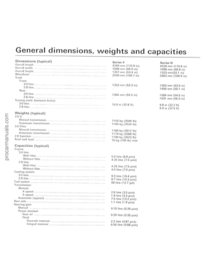 7
7 8
8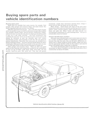 9
9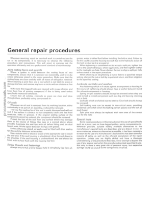 10
10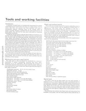 11
11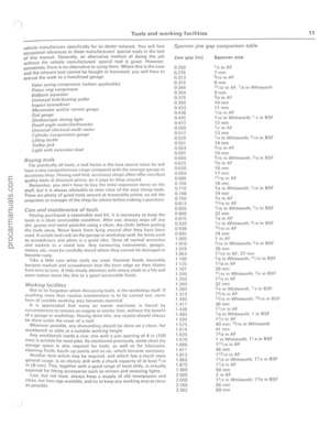 12
12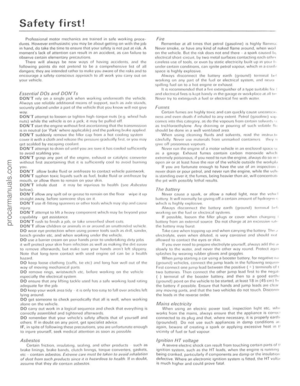 13
13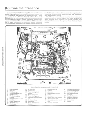 14
14 15
15 16
16 17
17 18
18 19
19 20
20 21
21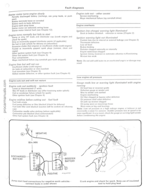 22
22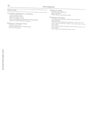 23
23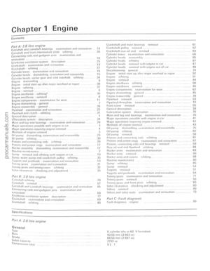 24
24 25
25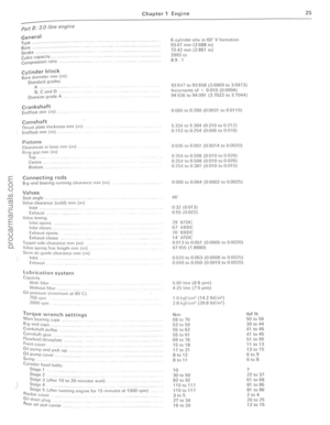 26
26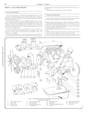 27
27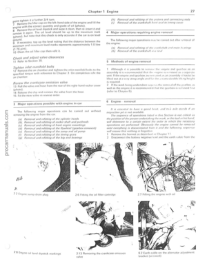 28
28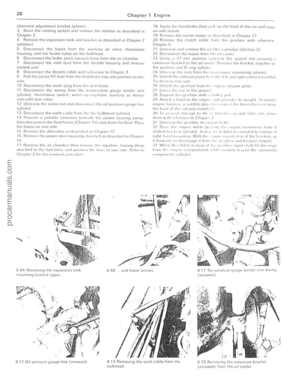 29
29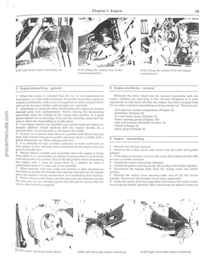 30
30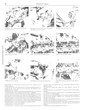 31
31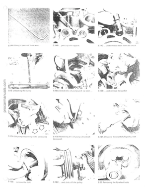 32
32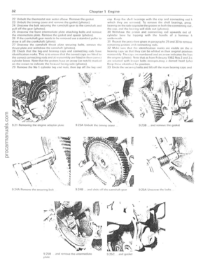 33
33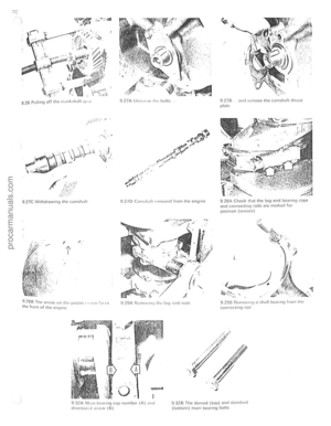 34
34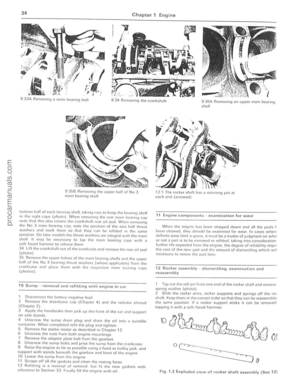 35
35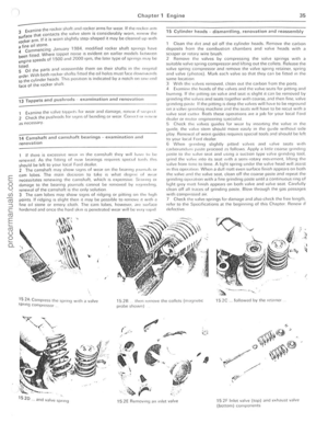 36
36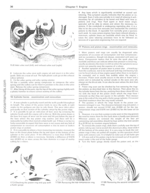 37
37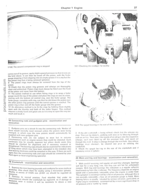 38
38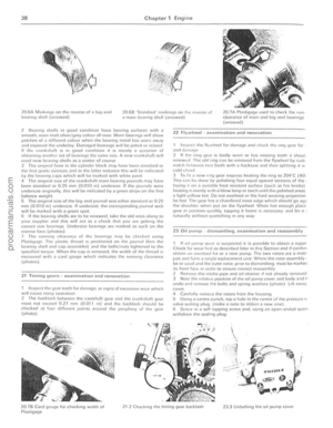 39
39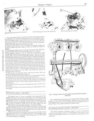 40
40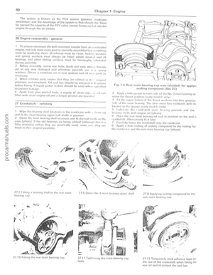 41
41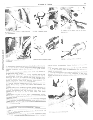 42
42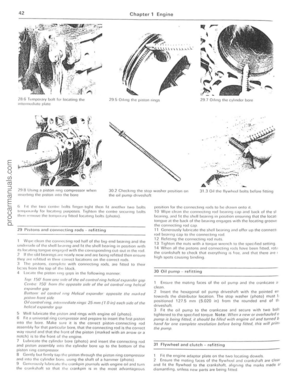 43
43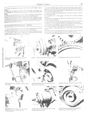 44
44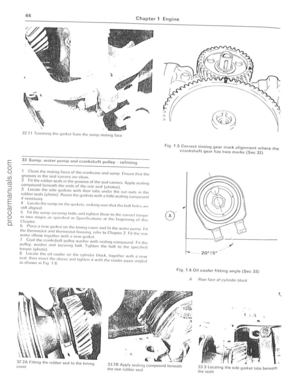 45
45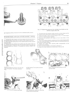 46
46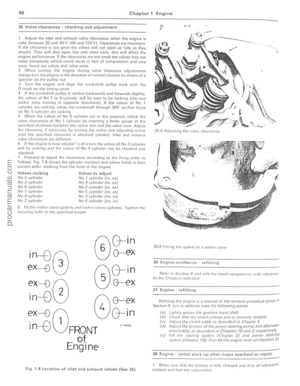 47
47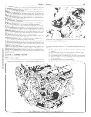 48
48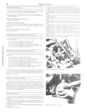 49
49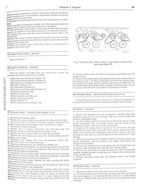 50
50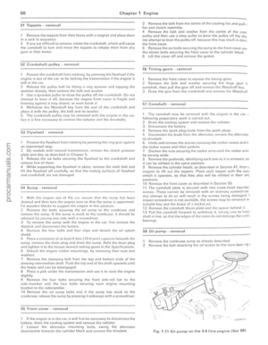 51
51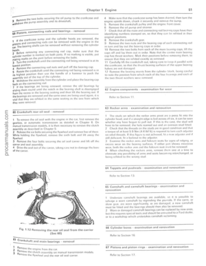 52
52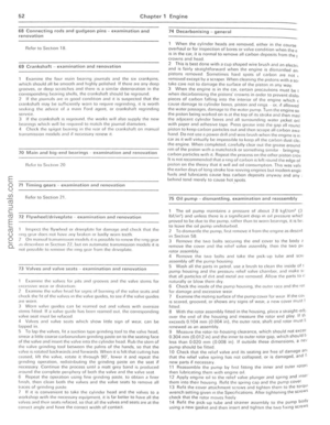 53
53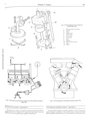 54
54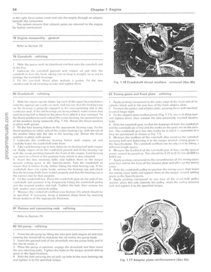 55
55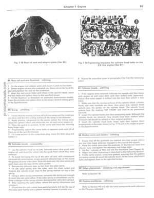 56
56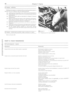 57
57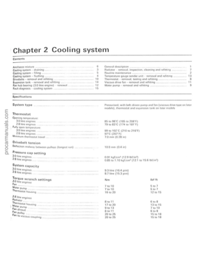 58
58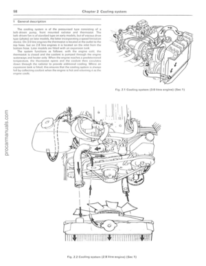 59
59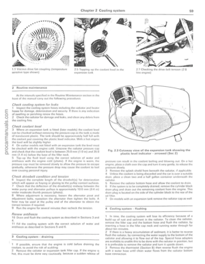 60
60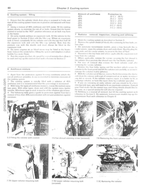 61
61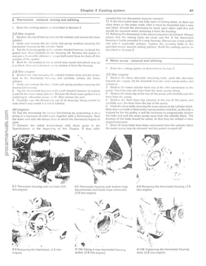 62
62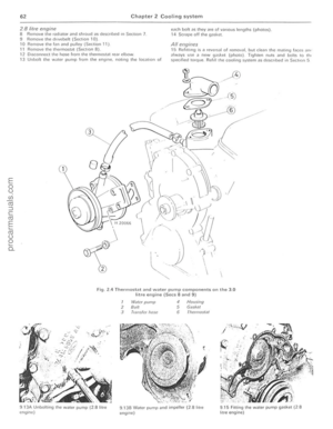 63
63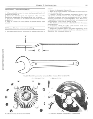 64
64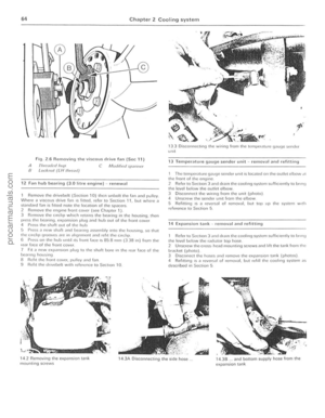 65
65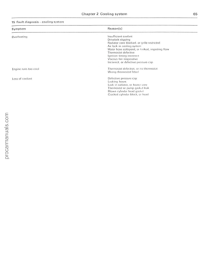 66
66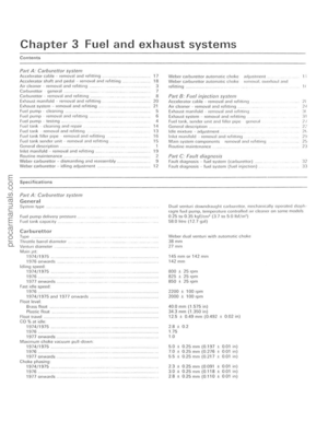 67
67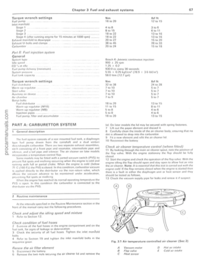 68
68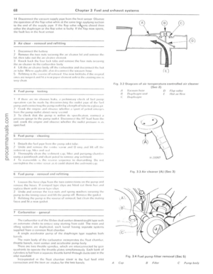 69
69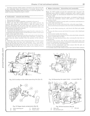 70
70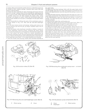 71
71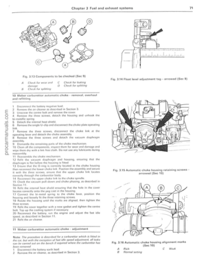 72
72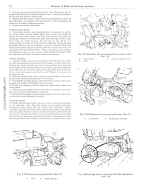 73
73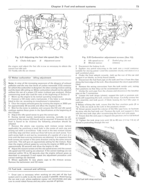 74
74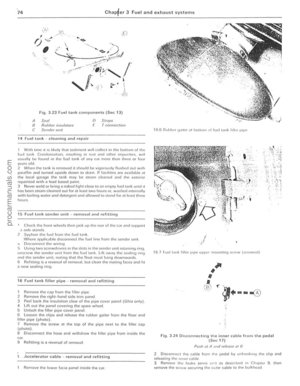 75
75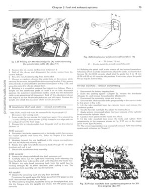 76
76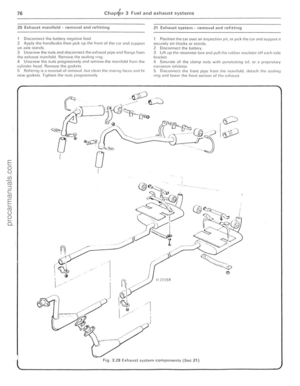 77
77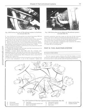 78
78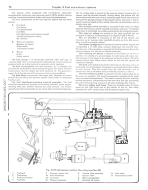 79
79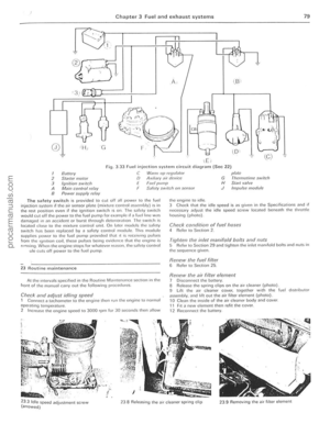 80
80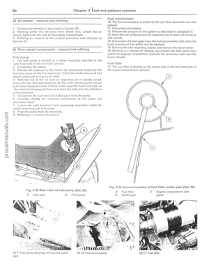 81
81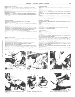 82
82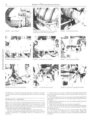 83
83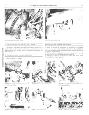 84
84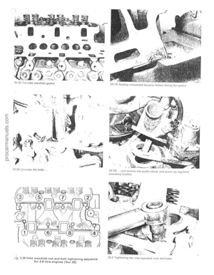 85
85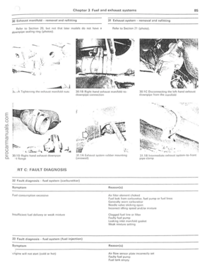 86
86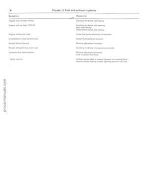 87
87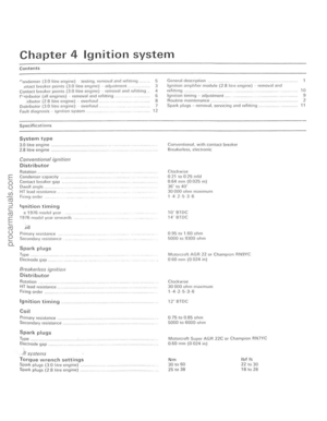 88
88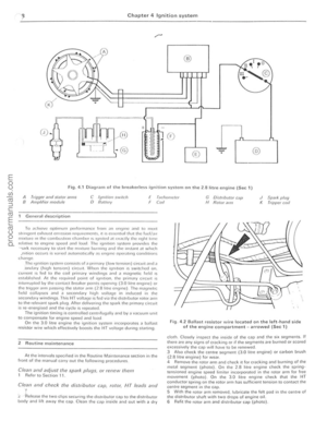 89
89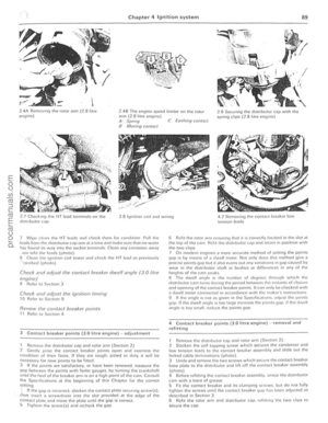 90
90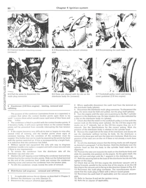 91
91 92
92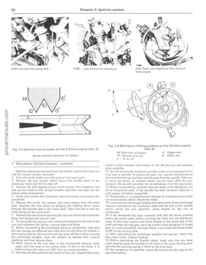 93
93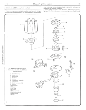 94
94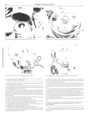 95
95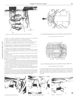 96
96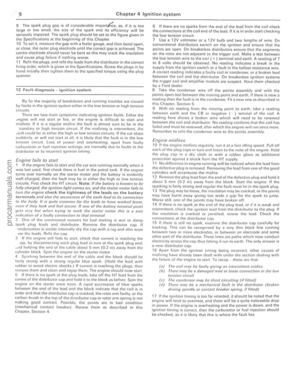 97
97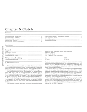 98
98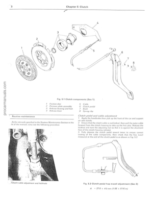 99
99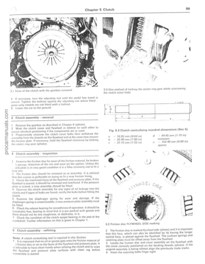 100
100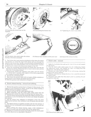 101
101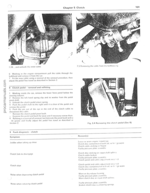 102
102 103
103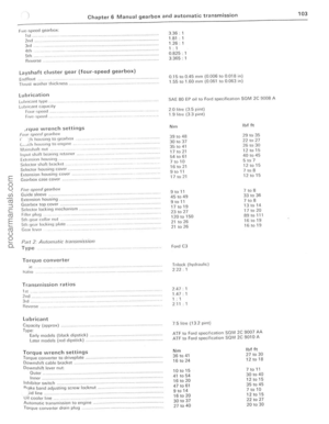 104
104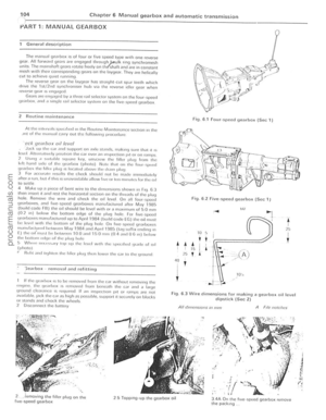 105
105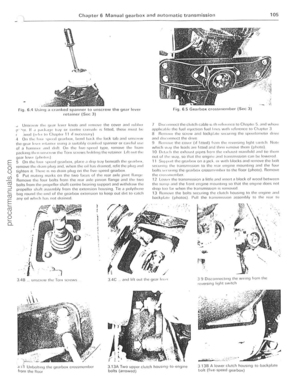 106
106 107
107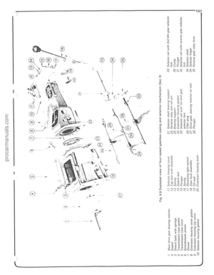 108
108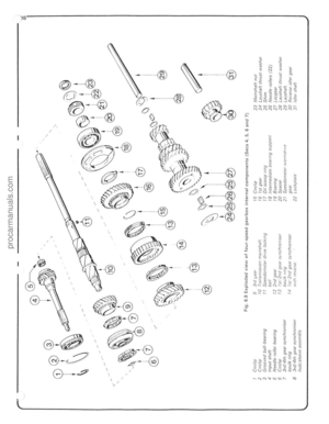 109
109 110
110 111
111 112
112 113
113 114
114 115
115 116
116 117
117 118
118 119
119 120
120 121
121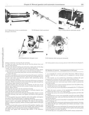 122
122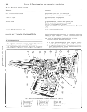 123
123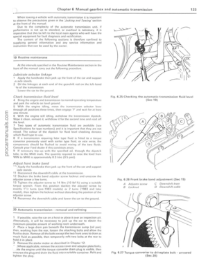 124
124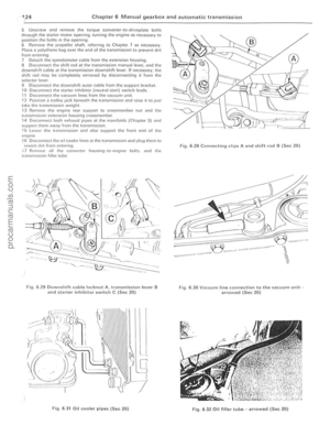 125
125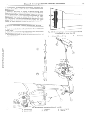 126
126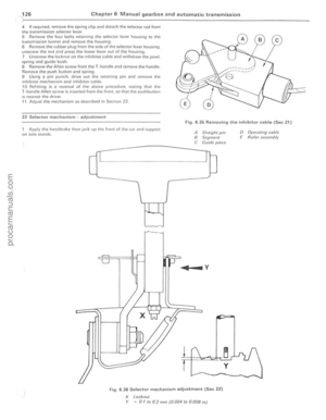 127
127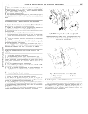 128
128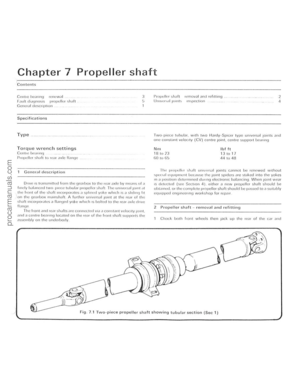 129
129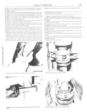 130
130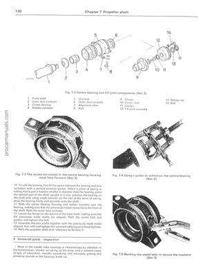 131
131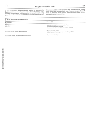 132
132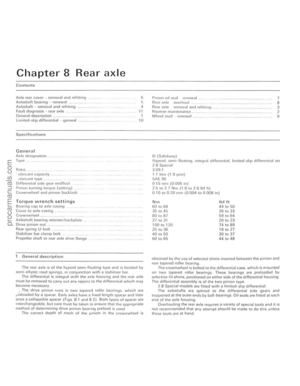 133
133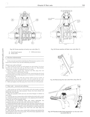 134
134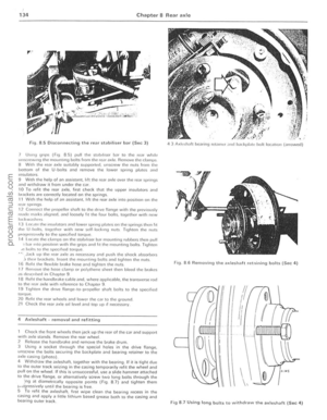 135
135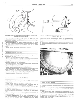 136
136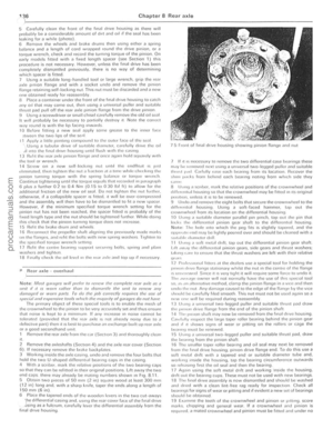 137
137 138
138 139
139 140
140 141
141 142
142 143
143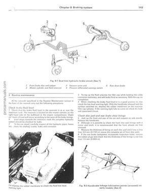 144
144 145
145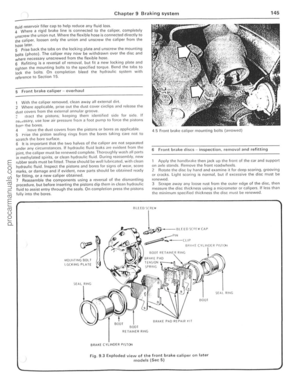 146
146 147
147 148
148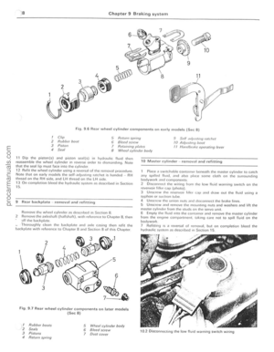 149
149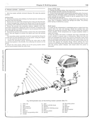 150
150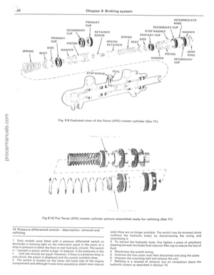 151
151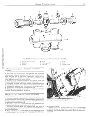 152
152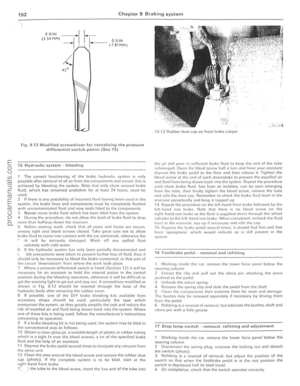 153
153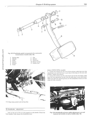 154
154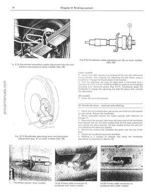 155
155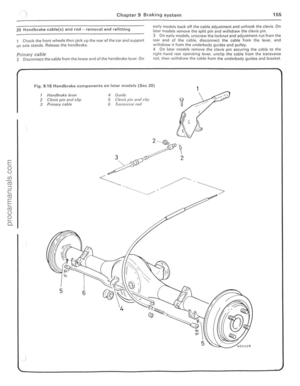 156
156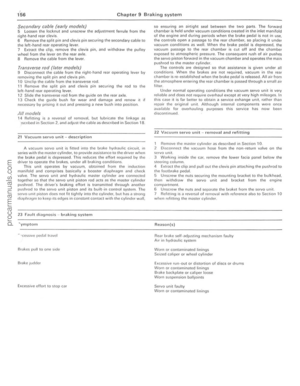 157
157 158
158 159
159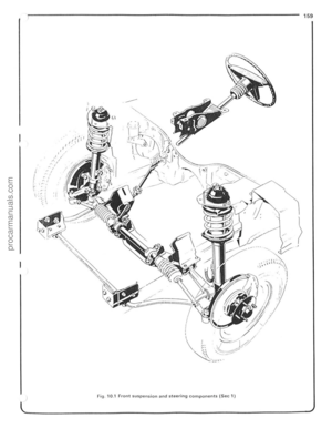 160
160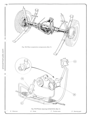 161
161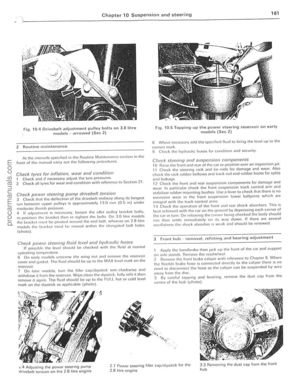 162
162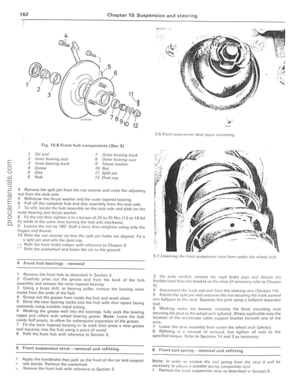 163
163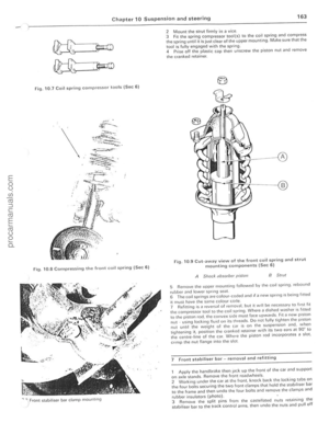 164
164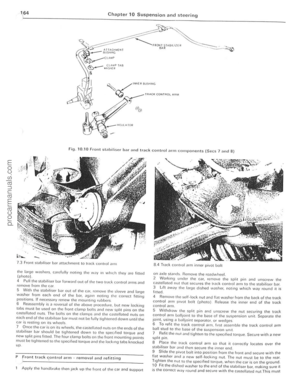 165
165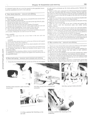 166
166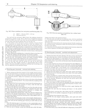 167
167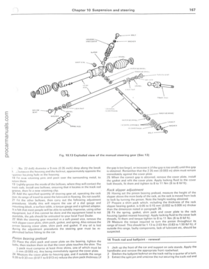 168
168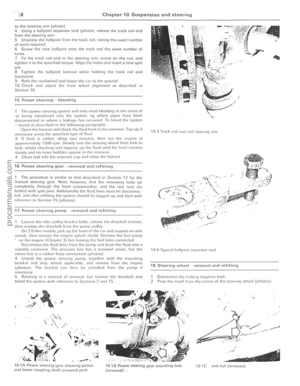 169
169 170
170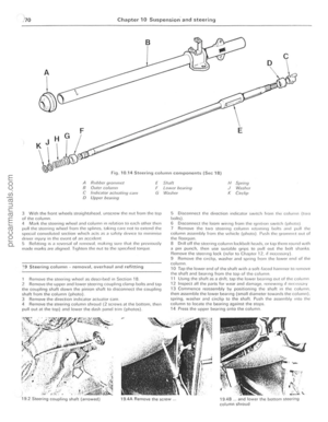 171
171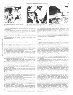 172
172 173
173 174
174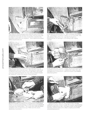 175
175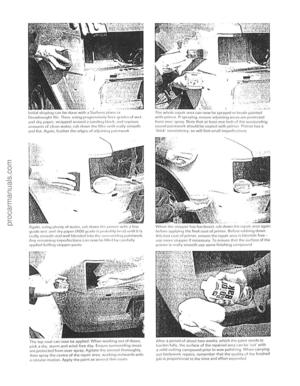 176
176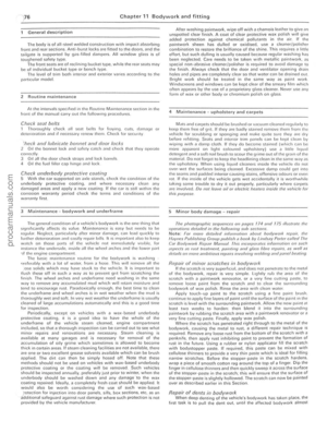 177
177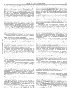 178
178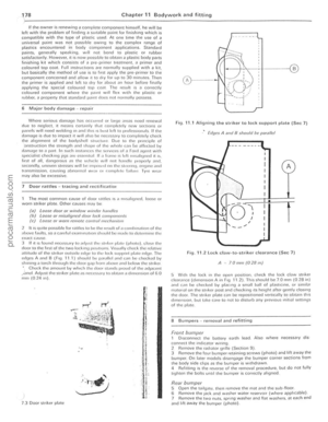 179
179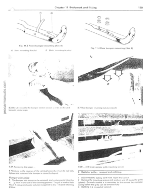 180
180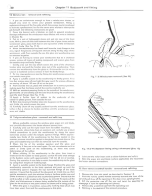 181
181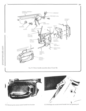 182
182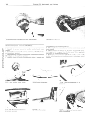 183
183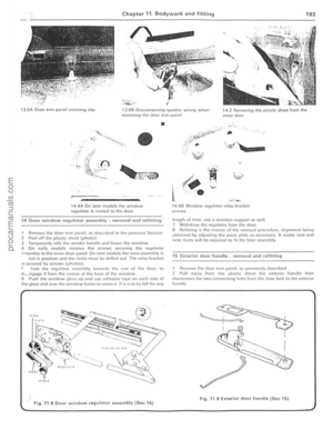 184
184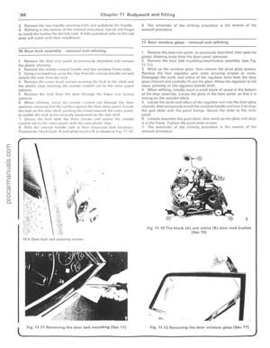 185
185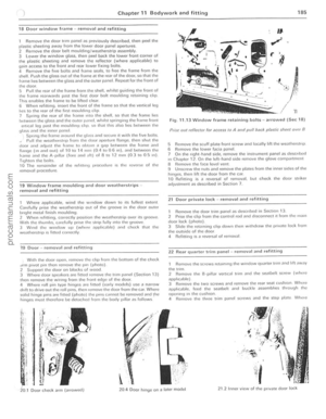 186
186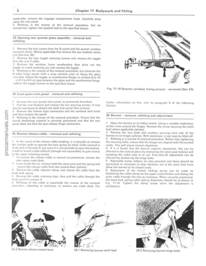 187
187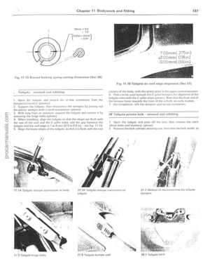 188
188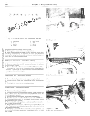 189
189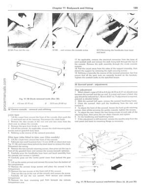 190
190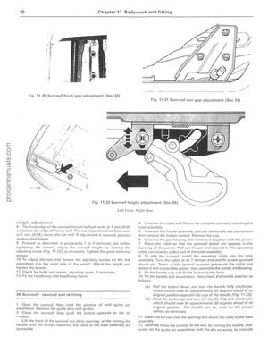 191
191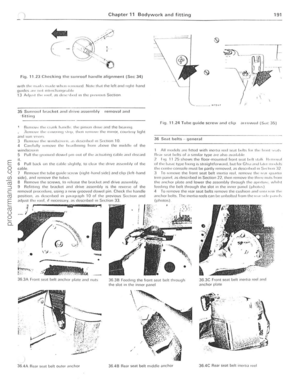 192
192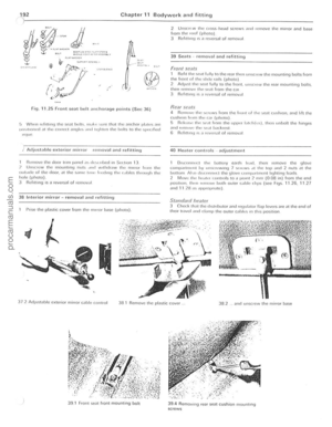 193
193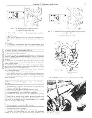 194
194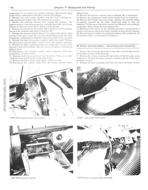 195
195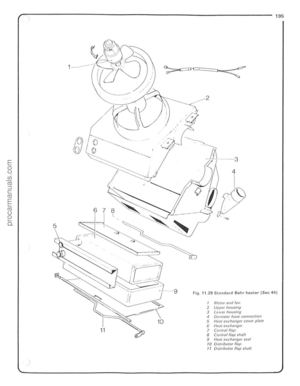 196
196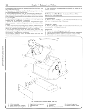 197
197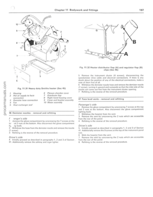 198
198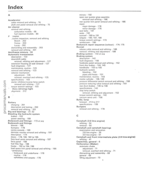 199
199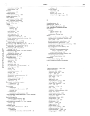 200
200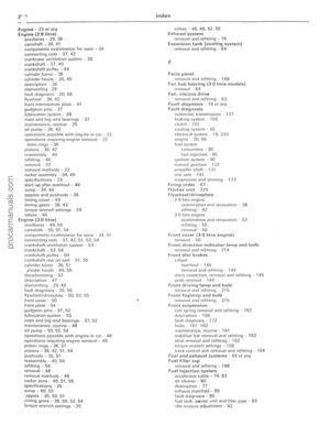 201
201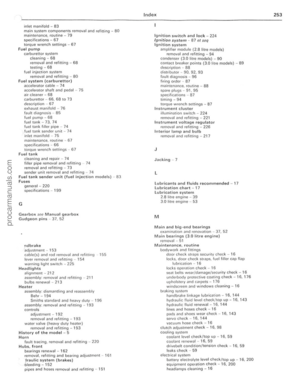 202
202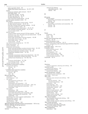 203
203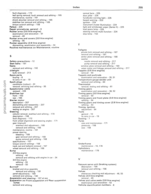 204
204