Page 97 of 205

,6 Chapter 4 Ignition system
9 The spark plug gaf} is 01 conside rable impor1~e. as. if it is too lilrge or too small. the size of the spark ilnd its efficiency will be seriously impilired. The spilrk plug should be set to the ligure given in thl} Specifications ill the beginning of this Chapter; IOTa sel it, measure the gilp with a/cere, gauge. and then bend open. or close. the outer plug electrode untillhe correct gap is achieved. The centre electrode should never be benl as this may crack the insulation ilnd cause plug fAilure if nothing worse. 11 Relit the plugs, and re/ilthe leads from the distr ibu tor in the correct I"ing order. which is given in the Specifications. Screw the plugs in by hilnd initiilily then tighten them to the specified torque using the plug spilnnel.
12 Fault diagnosis -ignition system
By lar (he nlo1jori (y 01 brCJkdown and running troubles ilre caused by InUits In the igrlOlron system er(her in (he low (enSlon or high tens ion circuns There LJratlon or fuel Injec tion Setlln(Js, ilre normally tllle to faults in the d,strrllulOr Or 10 Incorrect I(Jrlltion tlllllrl!J .
Engine fails 10 staft 1 If the engine falls to StM( and t he cal was IIJnning norll1t1l1y when.t wns IJst used, first check ther e is fuel in the petrol wnk. If (he engille tums ovel normally on (he starter 1I10tor and the bilHery is evidently well chmged. then the lault mny be in either the high or low tension circuits. Firs( check Ihe HT circuit. Note: If lire hal/cry is known 10 hI! {(Illy ch,}lged, Ihe ignilion liglll cOllies on, ,1I)d Ihe s/arler 1II010r {,lils /() tum IIIe ongine check the tightness o f the le'lds on the biltlely terillinilis ,1I)d <1Iso (lte seCUIIHWSS oflhe e,l,th leold (0 irs cOllllec/ion 10 tire body It is qui(e common for tlie le,1(ls /0 Ii,}ve wOlked loose. l.'vc'1I If Ihey look ,1n(/ lecl seclI,e. /I one 01 the boll/my ((:{minM {Josts [11.'1.1' vC'IV liot wi".." (Iyiny (0 wOlk Ihe s/mler 1II0tOl (his is ;/ sUie IIId'C,7/IUI/ 0/ ;/ I;wlty COllllel;('On 1(1 1h.11Ie"lIillal. 2 One of tile commonest rOilsons lor bad stmtln!J IS wet or d;UllP sp,uk plug lead~ and dlstribu(or. Hemove (he distllblltor cap. H "JOdenSil(Ion is v iSIble IIlte!llillly dry the CJp With il rag and also wIpe ;lCf the leads nelu the cap_ 3 If (he enUiue sull fmls 1 0 St.l.t. check that cunent IS reachlllg (he JUS, by dlscounectln!1 ench plug le,l<1 in turn ilt the sp1Hk plllU end, .. ,ld holdlllg Ihe end olthe callie about 5 mm (0.2 Ill) aWilY from the cylillder block. Spin the enu'ne all the sta rter motor. 1 Spa,klllg between the end of the cable ilnd Ihe block should he fa"ly strong With J strong leuulm blue spark_ (Hold (he lead WI(h wbber to ilvold elec(IIc shocks) If Clluelll is reilching (he plugs. then rel110Ve them and clean and reg,lp them. Tho engine should now SWrt 5 If there is no spilrk ilt the plug leilds. wke of! the HT lead from the cenlre of the d'sltibutor C
6 If Ihere me no spmks Irom the end of the lend 110m the coil check the connections atlhe coil end of the lead. If il is in order 5(31 1 checking (he low tension circuit. 7 Use iI 12V voltmeler or a 12V bulb ilnd two leng(hs of w ire. On conventional distributors switch on the ignilion i1nd ensure tha t the points arc open. On breakerless dlstlibulOlS ensure thilt Ihe segments on the rOlor are nOt adJilcenl to (he triggel coil. Make a tes t between the low tension wire to the COil ( + ) terminal nnd eilrth. A leading of 7 (0 8 'lollS should be obtained. N o reJding indiCiites a break in the supply from the ignition swilCh or il f,1UIl in the ballast resiswnce wire. A correct rending indicn(es a faulty cojl or condensel, or n blok en lend between the coil ilnd the distrIbutor. On breokedess ignition systems the (rigger coil and ilmplificr module are suspect . H~ve (hem checked by a Ford dealer. . 8 Take the condenser wire off the points assembly Jnd with the points open test between the moving point ilnd eMth. If there is now a leildrng then the tault is in (he condenser. Fit a new one as dcsclibed in this Chapter, Section 5 9 W,th no reilding from the moving point to eilrth, wke ,1 reildrng between eil/th ,1nd the ell or negiltive ( - ) teminal ot (he COIl. A rendm(J here shows a broken wire which will need to be renewed hetween (he COil ilnd dis(rihutor. No retlding confirms thil1the coil hilS failed ilnd must be renewed, afler which the eno"te wdl run once more Rcmtmher (0 rel,t tho condenser wire 10 the pomt$ ilssemhly.
Engine misfires 10 If the enOlnr. mlsfues re!Julariy. run It ilt a f~st irllrng speed. Pull off eilch 01 the plu(! C,lpS III hUll nnd hsten t o (he note 01 the engrne. Hold the phl(J cnp In il dry cloth or with a rubber g love
other Pollt of the dlstllhu(or. These lilles J,e p,lths which now conduct electllcit y Jcross the CJp lhus lewng it run to e,,'th. Tile only answer IS a new distllbutor CilP_ 16 APilit frorn the Ignition tll1l1ng being Incorrect. other Ciluses of rlllsl,,,ng hilve already been denl( w l(h under Ihe section dealrng with the f,lriUre of Ihe enuine to star I. To reCi!p - these 0110 Ih,lt:
(,J) The cOllm.lV be {,lufly giving ,111 iniNmil/elll mislile (b) Thele limy he ,1 (/iJmiJged wile or loose cOrlflee/ioll in till! low (eflsion circuil (c) The condensel /II,lY I;e shOll circuiling (i{ filled) (d) There nwy be a meehanic,lllolUI! IiI Ihe dis/flbll/or (bfOken dliving spindle or eOlllac/bleaker spring. if filled)
17 If the ignition (iming is too far reto1lded, it should be noted thallhe engine will tend to overheat. and there will he a quite no(iceable drop in powel. If the engine is overheating and Ihe power is down, and Ihe ,oni(ion tim in!) is correct. then Ihe carburenor or fuel injection should be checked, i1S ,I is likely that this is where the Iilult lies.
procarmanuals.com
Page 98 of 205
 Clutch llsscmhly lemOY,\" C lutc h cilhle .efluwal._
Clutch
Clutch !Jedal rClllovnl illld ,cflltl\"U
Specifictions")
Chapter 5
Contents
CIUICh il$scmhty '"SIJoCcl'Qn . Clu\(;11 assembly 'Urn!!ll!) Clutch llsscmhly lemOY," C lutc h cilhle .efluwal._
Clutch
Clutch !Jedal rClllovnl illld ,cflltl"U
Specifictions
Genera l Type ..... Clutch (lise (hamClcr lining tlnckncss Clutch pedal hcc "
Torque wrench setting Pressure plate (Isscmhly
Gene.al description
,
5 3 1 8
All manu:!1 transmission madllis covered by this manual nrc lilted Wilh a singlo dl3phrilgll SpllJlg clutch. The unit COlllt)riscs il steel cover which is dowelled and bolted to the tear lace of the lIywheci ilnd conla i.lS the pressure plnte. diaphragm spring and fulCrum .ings . The clutc h " iClio n disc is
ee to slice along the splineJ gearllox
Inpu t Shillt and is held in posi t,on between the flywheel and the pressure plate by the pressure of the pressure plate spring , Friction linIng materiill is riveled 10 the d,sc and II has a spring cushioned hull to absorb transmission shocks and to help ensure a smoo th take oft. The circular diaphrilUm spring is mounted on shoulder pins ilnd
'Ield in place in the cover b.,. two fulcrum rings . The spring is also held ,0 th e pressure platc by three spling steel clips which are rive ted in
posi tion .
The
clu tC h ,s aCluated b.,. a cable controlled b.,. the clulCh pedal.
Clutch '0Ie,150 bCilfl"U -remova' and wl,u,"g Filult (ioilU"OS'S -clutch Generill descllptlon . noutlilc rn,untenanco .
SlIlgle (Iry plate. dlill)hragm sprong. cilhle ·ope.ated 241,3 rnm (95 Ill) 381 nun (0 15 In) 27.01 40mm (1.OG:i 0 .16,n)
No. Ib l It 16 to 20 12 10 15
G 9 1 2
The clutch release mechanism consists 01 a .elease leve. and a bearing which conwcts the lelease Imgers on the pressure plilte assembl.,.. The eHect of an.,. wear of the friction ma terial in the clutch is adjuSled out b.,. means 01 a cable adjuster at the lowel end 01 the cable where it
passes through the bell housing .
Dep.ess lng the clutch pedal actuates the clutch release leve. b.,. means of the cable . The lelease level pushes the lelease bearing
forward to bear against thO release l ingels so moving the centre of the diaphf()gm sprong within the annular rings which act as fulcrum points.
A s th e centrO of thO spring is pushed in. the outside of the Spling is pushed OUI. so Illoving Ihe pressure plme backward and disengaging the p.essu.e plate flom the /tielion disc . When the Clutch pedJI is Icleased. the diaptllaglll spring torces the plessule plate into contac t w ith the frictIon linings on the d,sc and at the saIne t,me pushes it a flactlon 01 an InCh fOlward on I\S splines . The
disc is now fuml.,. sandwic h ed between the plcsswe plnte Dnd the
flywheel. so the d.ive IS laken up.
procarmanuals.com
Page 99 of 205

Ruutine 1\1,lintC!1aIlCC
I FrwllO\" d,sc ? }\"\".HIlfL II/\"e ilHLwlJly J \"I.·oR /II .fJ oml 1001, ./ 11\",.\"\"se /,.\"w\"")
Chapter 5 Clutch
?
4 7
/ ,
Fig 5.1 Clutch components (Sec 1)
Ruutine 1\1,lintC!1aIlCC
I FrwllO" d,sc ? }"".HIlfL' II/"'e ilHL'wlJly J "''''I.·o'R' /II .'''''''fJ oml 1001, ./ 11"',.""se /,."w"
AI tl1" U(itHv;lls spec(hud ((1 lh" llolll((1(J M ,((ntcnanCI! SeCI(OIlIll Ihe 111 of 11((1 Inilnu;!l. callY (Jut Ihe follow,,,\) pI<)c"dUlu
5 C"Ma 6 CI(I((:/' /1I:d,d 7 Rllsh 8 SI>tJlly dil'
CII/teh pUdo1l and c,1hle adjustment 1 Apply the handlH,lke til(:" J'lck lip the h01l1 ulthe Cill iII ld support 011 ilxle sl,lnds 2 Ensure thilt the c illtd, c;Jble 'S not klilked. Ihell pull the nllwr cilbt e 10lWilid hum the ch,tch houslI1g to lake up the f rec pl,lY Release the locknut ,1ud lurn the a(illlstln9 Ilut ~o thilt 11 IS an,lulst thc "i>utl1lenl f,Ke of the clutch houslnU (photo) 3 Fu lly dcp,e~s Ihe clutch pedill seve'ill ulnes 10 en~u'e correct seat ln\! of Ihe cable components. then check thilt the hOI! t(<
F ig . 5.2 Clutch p edal fr ee travel adjustment (Soc 2 )
A .. 270t40mm(106± O/6J1l)
procarmanuals.com
Page 100 of 205

Chapter 5 Clutch 99
--.;,:;.~.--.
. '
3 I V,,'W 01 Ihe clutch wIth the Ue,IIbox r~movcd
1 If IH,<:~SS;lIy. ill'" Ihe
sOllie cady modcis ;lIe lIot lilted wlih a lock"ut 5 Lower the C
3 Clutch .. ssembly -remov .. 1
I Remove the ~Jenrbox .. 5 described in Chapter G (photo). 2 Ma,k Ihe chltd, cove,
e,"""'! idcnll<:nl positionin\] illhe cumponelllS .. re Ie· used 3 l"O'lre~slvcly ullSCWW Ihn clulCh (".ove, holts then Wllhdr"w Ihe a,,~,,",I!ly homlhe dowels on Ihe lIywhnol ~nd
Illn h,,;I IOI1 pl;lIC IInecossary. hold Ihe lIywlwel siailonary hy 10d",U
II", ~1'''I'·r ""!I Uoar (photo).
1 Cili lch assemhly -inspectioll
Ex;"nIlIO IllI] 1", :lio n dISC lor we,ll ollhe In<:lIon 1ll'lIe"al. for bwkell .j ,;pllilUS. (ilSlull rOll of the rilll "ml we;lr all the splmos Unless the
. 1I:h plate IS In ve'y \Jood condlliull II is ;I false "cono"'y not 10 hi J
II""" ono ? The I"ctron d,sc should he ren ewed as as "ssemhly II IS adviscd Ih.ll th,s co\m;r~ IS prelelahle to lIymB 10 1'1 .. IIew I"ctlon IIIHIlU· :3 Chec k tho tnJchlned Iilces 01 Ihe flywheel "nd p'essure plate . lithe Ilywheells scoled. II should he relllove<1 "lid m~ch",cd Illhe preSSIJle pl.lIe IS scored.
cluic h nnd II si9nS 01 le"ks "re found. rec t,ly Ihe le"ks be/Ole hlling Ihe
clutch.
5 E x nmlllC Ihe diapl""9fll sprinu lor wear ,lIld <1
be f illed 6 Check Ihe release bearinu for smoothness 01 opcration.11 should be re~son"bly hee. benring in mind Ilwt II IS pre ·p"cked WIth grease "nd Ihele should nOI be ;lny roughness. or slac kness. in il.
., Ch eck Ihe comt.tion ollhe dolCh spigol be .. ring in Ihe end 01 Ihe o""kshillt. Further inlorlllillion on this is given in Ch;lpICr 1.
5 Clu tc h assembly _ relitting
Note: A chI/eli CCII(r,l/ising roo/ is required in (his See (ion. I IllS IInpOllanllhal no od or gre.lse gelS onlO th(l friction mated,,1 01 h,c t,on diSC 01 on 10 the laces of Ihe lIywheel find pressure plalc. It ,~advisi,llle to have clean hands when rel'lIing the dolCh and 10 w ipe lho lIywheel ;lIld pressure [lla\\! surfaces wilh clean rag belore
I~assernhly IS s1
I
.... , ... "
'.
33 One method 01 10cklllH the Slarter lin!) \lo"r wlHle \II1SCleWll1U
the clulCh cover hailS
•
Fig . 5.3 Clulc h centr" lising nHllldrel dimellsio ns ISec 5 )
"
" ,
1626 111111 (061 ill) 25101ll11! (100 1ft) 3175 mill (125 1ft)
)
.. , . I .. ~ .
rI .• 44.15 mm (I 75 ill) IIImil!l(IfII (: ~ 15210111111 (6.00 ill)
.l/lf!f(!X
./J?f1. ' ,
.?!<'. , , ..... /
~/ r .... :./ .:..1('":'
'''r' ....... , .
. )i";; , i ,
. . ~:.. • j • ,
/'" , , -..
··E
"
.. . -
5.2 Friction disc FLYWHEEL SIDE marking
2 The friClion disc is Il,arkcd flvwlwcl shit· (photo) and il i$ impol1anl Ihal th is face . which can 11150 be idenl,lled by ils haVing the longe, cenllal boss. ;s plnced againSI Ihe lIywheel. The cushion springs and reJaining pl"te muSI b(l ollsel away hom lhe Ilywheei. 3 Loca te the Inctlon disc "nd cover "ssembly on t he lIywheel with the cover cOlleclly positioned on J he loc .. ting dowels (phOto) . If lhe oliginal assembly is being , efllled .. lIgn Ihe previously made marks .
<1 Insell Ihe reta,ning boilS I"'ger Ilghl.
,
I
I
I
I,
procarmanuals.com
Page 101 of 205
htIJnlll!) 111\" ,: 1,,[, h cover holls
6.4 The plilSllC wlls which .cWin the fcl")
"00 Chapter 5 Clutch
53 Locmlll\J the (flCllon disc on the
f lywheel 5 .6 Cent,.,l ising the friction disc 5.7 TI\)htIJnlll!) 111" ,: 1,,[, h cover holls
6.4 The plilSllC wlls which .cWin the fclcJSC hcnrinl] in the lever (""owed) G 5 nt:lcas(l levor IOC,11;01) 011 the 1"1101 stud
5 The f"~lI()n rt.!;c must now be Cclltrilloscd SO Ihill when the (IllUme imd !Jci"loo~ .1<0 milled Ihe input shall splmes Will pass 1I110uUll the splines III Ihe )HCIIO!) diSC Id(!,lIly a wlille.s;,' dUh;h (;C!l!r()" Inpul ~h"fl shuuld be u~cd. hlJt ,rlh.'IIHI(,vcly a woodull 'lIilnd,!:i G,II1 h.., Ill.1
6 Clutch release bcnring removal 1Hl(1 rcfitting
Remove thc gcarbox "s dcscflbed in Chaptcr 6. Alternal,vely. illhe cngi ne is to bc removed for repairs. acccss 10 the rclcilse bcminy ,s possible leaving lhe gearbox in position. 2 loosen and back oil the cable adjustmcnl milS. 3 Whcre npplicable. plisc lhe ciulCh cnble fuhhel gaitcr flOm the bell housing nnd unhook thc cahle end lotting from the release fevel. <1 Puilihe release I)ealing hom the \Juide tube. Whcre necessary use a scrcwdrlver to pflse the f)Caring flom the Icvcr and lelease the pfas\lC
tabs (photo).
5 Pull t he rclease IiNCI sldcways to d,sengage it from t he pivot retaining stud (photo). thcn withdraw ,t ovcr thc IJuide tube ,1nd input shah
6 The rele ase beann\) is supplied completc w ith lhe huh (photo). If fC(luired. thc two componenlS can be scparated usinU a VICC and soh metal drill.
)Before relltllng (hc releasc bcariny. apply a lillie molybdcnum "."ase 10 the \llude tubc and contact laces of the release lever 8 flefl!1lng is a ((,versal of remov~l. butllnally chcck the clutch pedal and cable ndlUsllllenl JS descflbed in Seclion 2_
7 Clutch c;lllic -Icnewnl
Apply tlol) Io.",dl!<"k" llien lilCk "I' lilt: j'onl of 11"1 Gil o1l1d suppor( on ax il! ~!and~ 2 PIIS" th" dUlch callie whlJel (jilll'" horn lh" h'·lIhou~u'(j. lousel! the ati,US111l'JllI nul(s). ;IIHI unhook the c;,I,I" ,·nrl IlIllllB hOIll lhe release h,v,,, Pull off the !Jalter (phOlUS) 3 Ikmuv" ti,,) c,lhle frorn lhe hole II) lh., 1,,·lIh"u~"l\J. nUlo)\) lhe posltlun of lhe slccve (phOIO) <1 WOlkln\l illS Ide (hC Cilf. remove the luw,,, I,,,",,, pallel lor
, '. ,
j'., ;. . , , , .;{
'-,
7.2A Prisc all the rubber Ualtef
.. ~
d
procarmanuals.com
Page 102 of 205
![FORD CAPRI 1974 Workshop Manual Chapter 5 Clutch
7 2B .. and unhuok Ih" Illller C<lhlr:
6 Wu,k,n\) rn 1111] <:n\)1I1O Gornp"ln",nl pull Ihe ,;alJle Ihouu!)h Ihe
h,Jlkhea d ,n
1l1 Icmuve II trom Ihe Gil 7 Fit the new cahle 1](/manual-img/11/56932/w960_56932-101.png "FORD CAPRI 1974 Workshop Manual Chapter 5 Clutch
7 2B .. and unhuok Ih\" Illller C<lhlr:
6 Wu,k,n\) rn 1111] <:n\)1I1O Gornp\"ln\",nl pull Ihe ,;alJle Ihouu!)h Ihe
h,Jlkhea d ,n
1l1 Icmuve II trom Ihe Gil 7 Fit the new cahle 1")
Chapter 5 Clutch
7 2B .. and unhuok Ih" Illller C
6 Wu,k,n\) rn 1111] <:n\)1I1O Gornp"'ln",nl pull Ihe ,;alJle Ihouu!)h Ihe
h,Jlkhea d ,n
1l1 Icmuve II trom Ihe Gil' 7 Fit the new cahle 1I;;lnu " levels,, 1 of Ihe lemoval p,ucr.:du,e. Ihen adlust the ped
8 Clutc h pedal-remova l
Wo,kmg insId e Ihe car. fCf1,OVC Ihe lower Inc,," p,mel helow Ihe
stcerinu colunlfl 2 Bemove the h:lt hand sp"n\J clip
p,vot shalt. 3 U nhook Ih " dulCh ped;,1 ,"IUln ~1)l1Il\J 1 Pus h lire I'c
'c"'ovr.: IIr" I",d,d 5 I'ush Iht) I'"' oul 01 th " "yu '" Ihe end ul Ihe clutch cahle 10
d'SCOIHleCi Ihr.: cal,l"
B"!1luvlJ ti,,, <:Iuld, pell,,1 plvull"'Sh. E~;,,""'e Ih" 1',,(1;,1 ,Hld hush lu' w,-,ar ,!Ild r! necess
~Ct;tlon 2
!) Fault dia\)llusis -clutch
Sympto m
Juddcr when laklnu up drive
ClulCh slq)S
Noise when dep,cs$UI\J clutch ped,,1
)
NOIse when ",I"as"'u clutch ped,,1
7 3 R~llII)Vln~J the ~ ,'hh, IrOIll Ihc h"tlhllu ~.n\J
FiU . 5. 4 Removinn lir e "hnch pe{!;!1 (Sec 8)
l1easun(s)
L,u,,,,, '" wr:r,n ""\1"'" ""JUnt'n~l$ (l"ld, d, sc ,;ool,I",,,,. \I'·d w,th 0'1. or 10" ··gs WOlll
Ciu1t: h c"I,l u ~1,~k""J ()I tr"ytd I'"ul ly ple~,>ure pl,He .1,>~e",IJI\'
Clu tc h d,sc stIC~"'\J Oil "'put slr,,1t spl ,o':>
Clul, ·" cirl,I"
I!'o~,," F
ClulCh ped,,1 nlld c"I,I" ,1dl\lS;,,,,,III (lif.V··:CI Clutdl d,~r: COIII
Fill,lty I"u~~uru pl"I" ",.~"",!)I{
WOIII or (lly rul~as,) "~''''"U F,,,"lJly VVOIII dut<..1r d ,sc U ' ,oput Sh,1!t "pl,,!,,~
Fau lly Il,u s,>ure pl.lle n,>,>uonbly H,oku", clulCh (j'St; Cl,,>",O,,,og ~PllIlU~
101
,
! '
. , .,
, , I
,
procarmanuals.com
Page 103 of 205

Chapter 6
Manual gearbox and automatic transmission
Contonts
oIrt 1: Mamml gCMhox
It dunosis - m,Ulllal ijc(l.box .!l)()x -emav,1I ;lIld ,efluing . Gc;ubo. (II-speed) -dsmamlln{J GC:UhOK")
)
Chapter 6
Manual gearbox and automatic transmission
Contonts
oIrt 1: Mamml gCMhox
It d'''unosis - m,Ulllal ijc(l.box .!l)()x -'emav,1I ;lIld ,efluing . Gc;ubo. (II-speed) -d'smamlln{J GC:UhOK (II -speed) -cxarninallon and renovatIon GCiui)o x (
Gc;'ubox (5-speed) -(hsmnnthng GC;lrho. (S-speed) -cxnrnin;l1iOIl
Specifications
Plut 1." Manual gearbox
Type ...
R ntios
Four·speed gcarbOI( : 151. ')n(! jrd 4th .... __ ........ .
Reyerse ....... _ ....... . 17
3 ,
8
9
16 11
" 15 10 1 6
13
7
Mil"'shah (4·spccd) Millnsh;'!!! (5,sJ>Ci.Idl nOut,nc Ill"mlcn;",ec
d,smamhng and reassembly _ Ihsm
Part 2 : Au(oll/otic (mn$mission I\lIlOrllill lC triln snHSSlon -removill ilnd re titt ing
OownsllIll cillJle removal. reflUing ilnd adlusunelll F.~ttlns,on hous"lg all seill -lenewal
Fault dlilgnOSIS ilutomilllC transmIssion ................................... . General dCSCflPilon ............... . Rouline milinlen;lflCC SeleC10l mechilmsm -MiluslfllCnt ................ . Selector mechilmsm removal. ovcrhaul ond refitling ................. . Stillier Inhllmor/revcrse lamr> switch _ removal and refitting
Four Or "'Ie forw,ud speeds (all synchromesh) and reyerSe
3.16 : 1.94 :
1.41
1 1 3346: 1
5 12 2
20 23 25 26 18
I" 22 21 24
E
procarmanuals.com
Page 104 of 205
od \joiuhox:
\" 2nd 3rd 41h .. 51h f\ovr;,so
Laysh aft cluster gear (f our-speed gearbox )
Elldfio<lt .. Thrusl w,lshm tluckuoss")
Chapter 6 Manual gearbo x and automatic tran smissio n
F1VO.Sp()od \joiuhox:
'" 2nd 3rd 41h .. 51h f\ovr;,so
Laysh aft cluster gear (f our-speed gearbox )
Elldfio
lubricatio n
Luh"(.
,rquo wrench settings F(}(If.SI!(',~d !lcar/lO x r fh h01l5,",0 10 HOol,box (. •.• ,(;1> Iw"sIIIIJ to 1'1I1J111H M.1,.\~halt "."
InplIl shafT hoaun» 11,IJIIUlr ExtellSl!lIl hous',,» ... Sf:h,ClOr Shilh IJJil~kel . Sciccto! housinO cove, .... Extension housin\1 cover . GeJlhO x casc cover
Flve·spccdgc,lfbox Guide sloeve Ex lOnsion housing. Geol,hox top cover Seleclor locking mechanism .... FilII), plu(1 51h He,ll cull,H nul 5th
Pari 2· Automatic transillissio n
Type
Torque converter
if! IWtlO
Transmis s io n ra tios
1 st 2nd. 3'd . Reverse
Lubricant
C~pacily (ilpprOX) . Type :
Early models (blnck dipsl ic k ) Laler Illodels (red dipstic k) ..
T orque wrench settings Torque convcrter 10 dr;veplille .
Do wnshift cable brac ke l
Downshift lever nUl: Duler. Inner.
Inhibito r swilCh
R'ake b;"Uld ~d!usling screw loc knu l .. .
lid l ine .... ... .. ...... ........................... .... . ULI cooler Ime . AU10lllilllC t",n~lI1ission t o engine. To rque conveilei drJin plug
3.36 : 1 1.81.1 1.26: 1 1 ,
0.825. 3.365 :
0.15100.45 mill (0.006 to 0.018 in)
1 .55 to 1.60 m!11 (0.061100.063 in)
SAE 80 EP oil 10 Ford spociflCatlon SCM 2C 9008 A
20 lit,e (35 pim) 1.9 lilH! (3.3 PUlt)
NIl
39104 8 30 to 37 35 to 4 1 17 10 2 1 54 to 61 71010 161021 9 to 11 17 to 21
9 to 11 4 5 10 49 9 to 11
17 to 19
231027 12010150 21 to 26
2 1 1026
Ford C3
Tnlock (hydrnulic)
222.1
2.47 : 1.4 7 : 1: 1 2 11 : 1
7 .5
htre ( 1 3 2 pUl1)
Ih l It
29 10 35 22 to 27 261030 12 to 15 40 to 4 5 5107 12 10 15
7 to 8 1 2 10 15
7108 331036 7 to 8 13 10 1 4
17 1 0 20 89101 1 1 1610 19
16101 9
ATF to Ford spec,fIC~lion SaM 2C 9007 AA ATF to Ford specification SCM 2C 9010 A
N m Ill f It
361041 27 10 30
16 to 2 4 1
2 to 18
1
010 15 7
to 1 1 41 1054 3010 40
1 6 10 20 12 10 15
4 7
10 61 35 10 45
9 10 1 4 7 10 10
1610
20 12 10 1 5
3010 37 22 1
0 2 7
2 7
10 40 2
0 to 30
, . ,
!
.5 ________________ ........... ........
procarmanuals.com
 1
1 2
2 3
3 4
4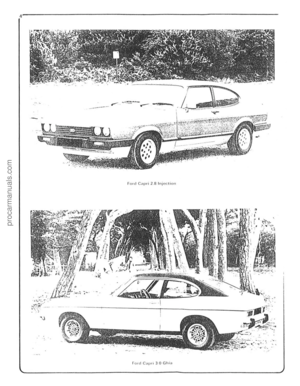 5
5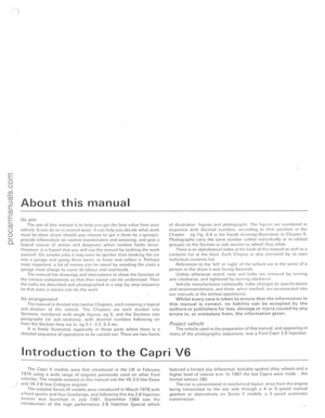 6
6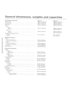 7
7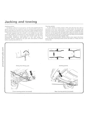 8
8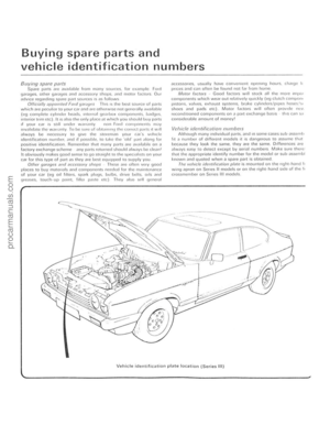 9
9 10
10 11
11 12
12 13
13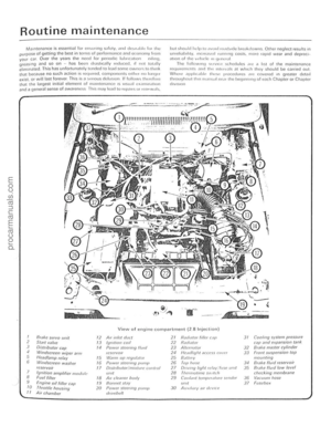 14
14 15
15 16
16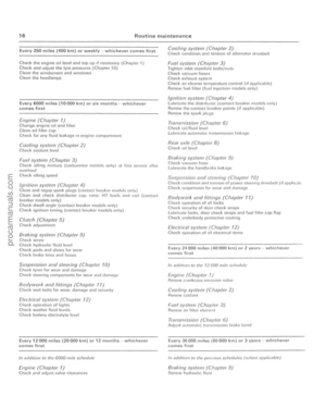 17
17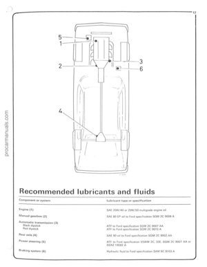 18
18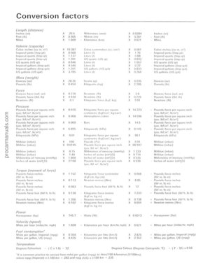 19
19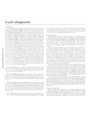 20
20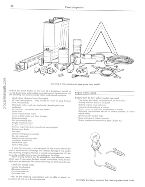 21
21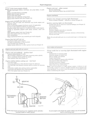 22
22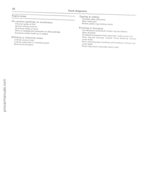 23
23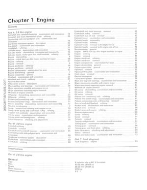 24
24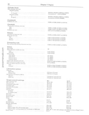 25
25 26
26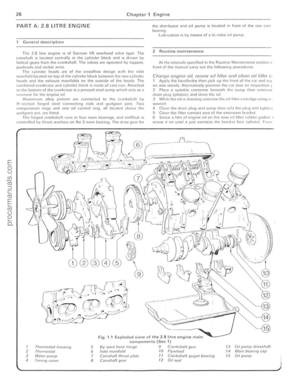 27
27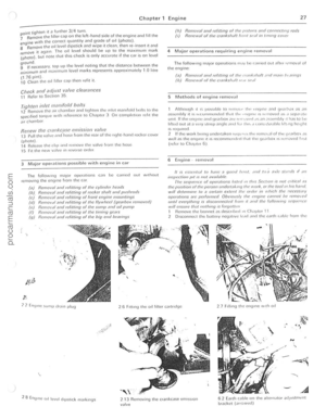 28
28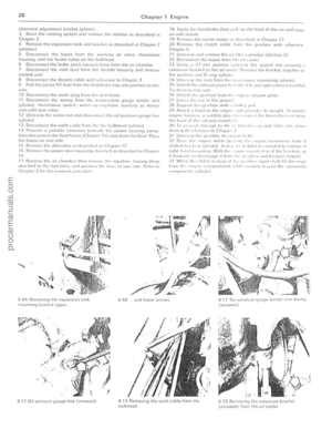 29
29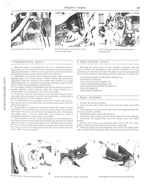 30
30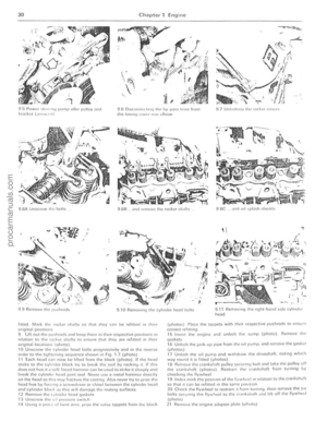 31
31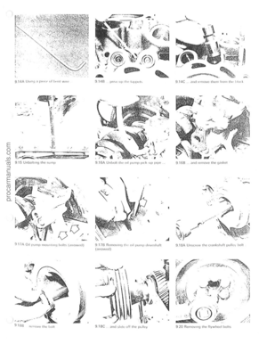 32
32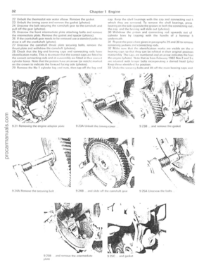 33
33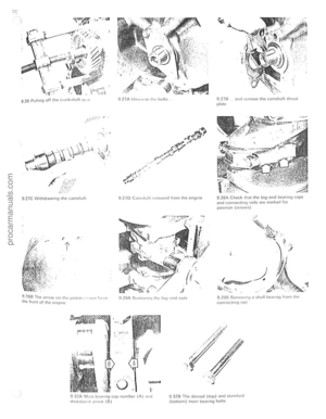 34
34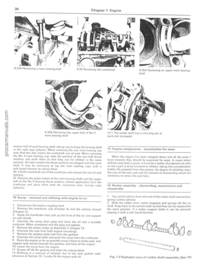 35
35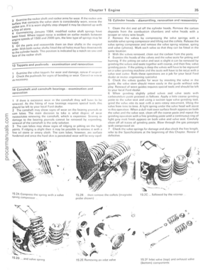 36
36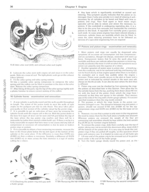 37
37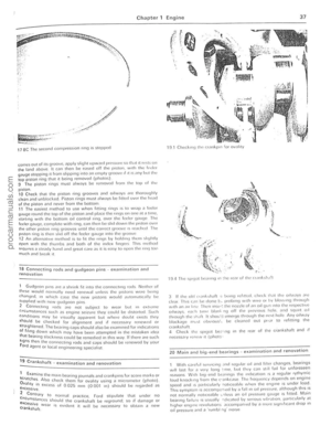 38
38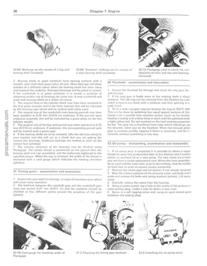 39
39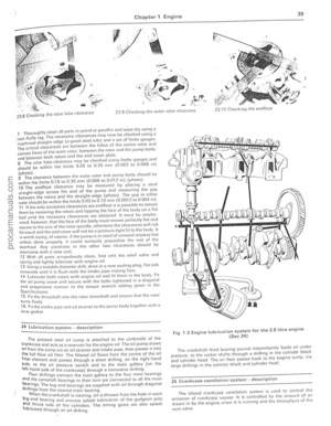 40
40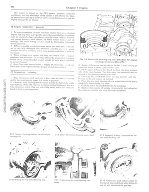 41
41 42
42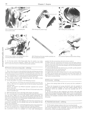 43
43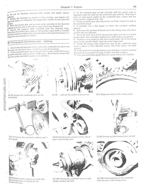 44
44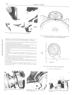 45
45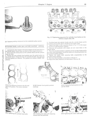 46
46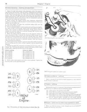 47
47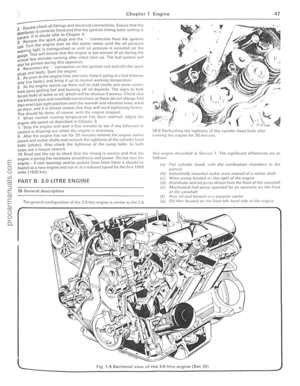 48
48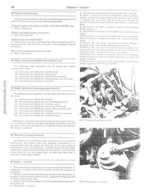 49
49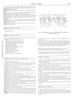 50
50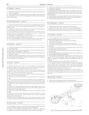 51
51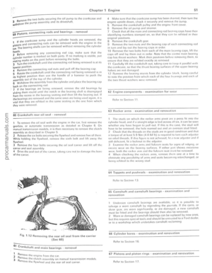 52
52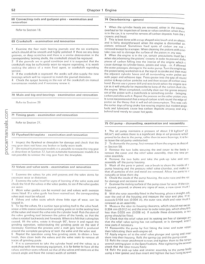 53
53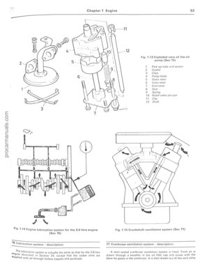 54
54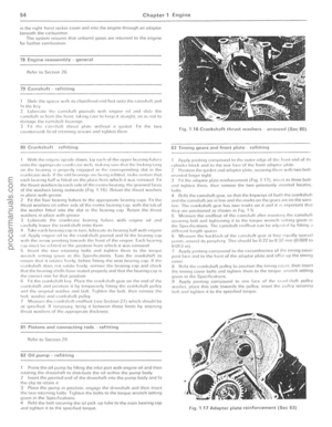 55
55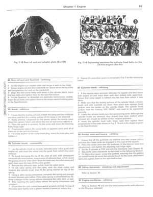 56
56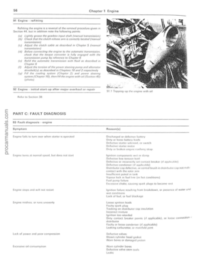 57
57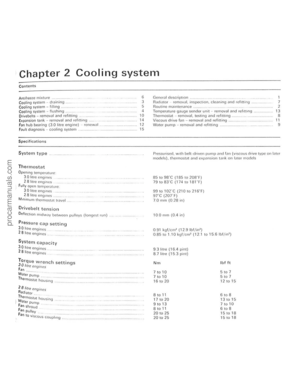 58
58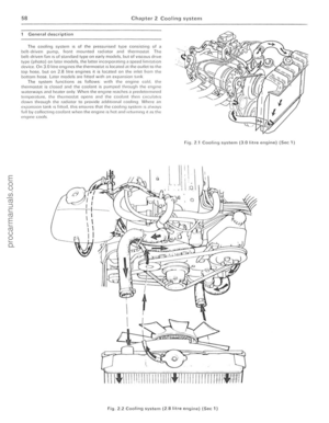 59
59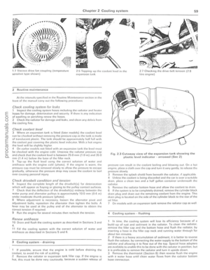 60
60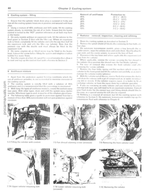 61
61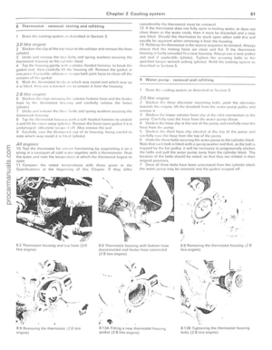 62
62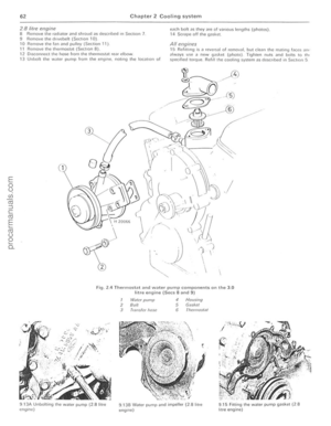 63
63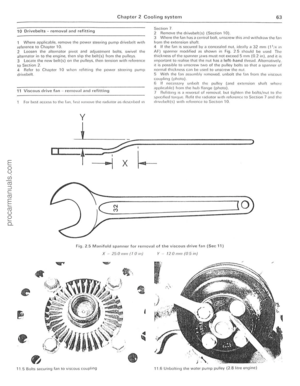 64
64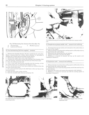 65
65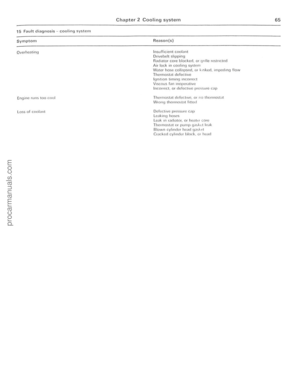 66
66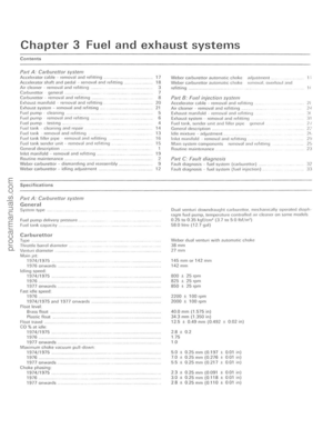 67
67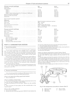 68
68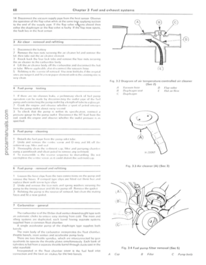 69
69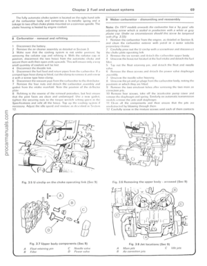 70
70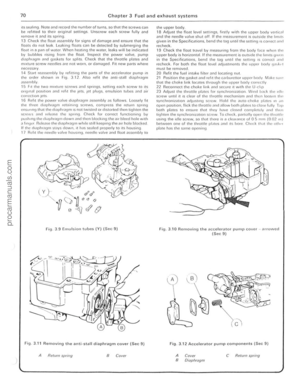 71
71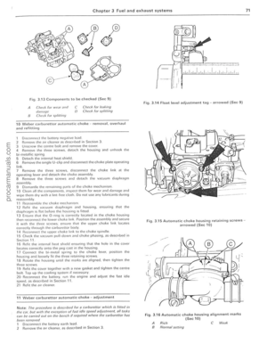 72
72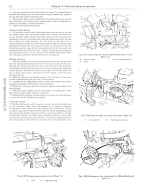 73
73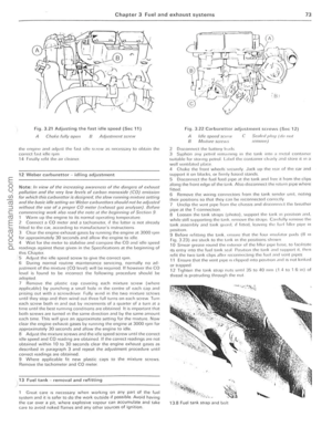 74
74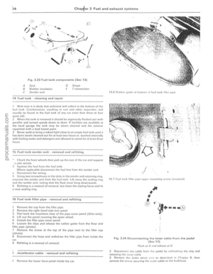 75
75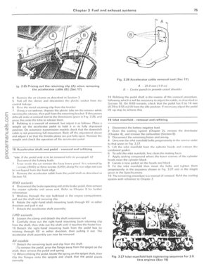 76
76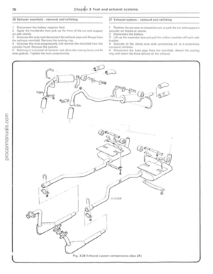 77
77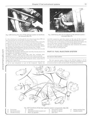 78
78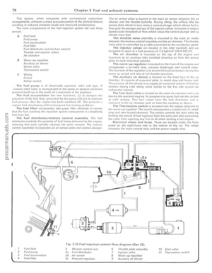 79
79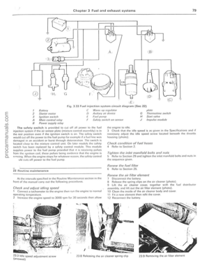 80
80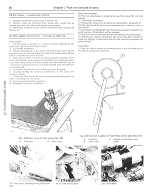 81
81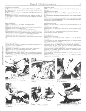 82
82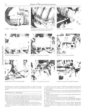 83
83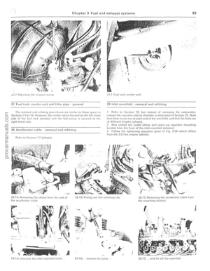 84
84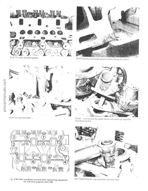 85
85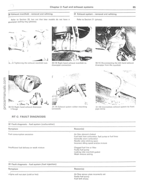 86
86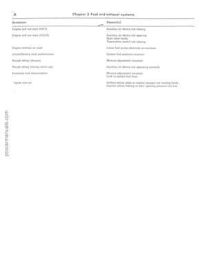 87
87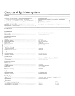 88
88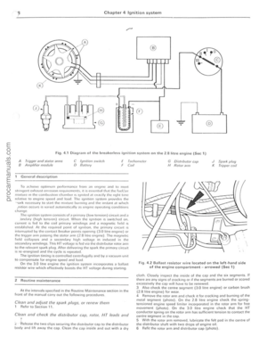 89
89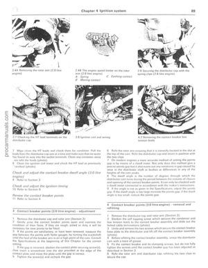 90
90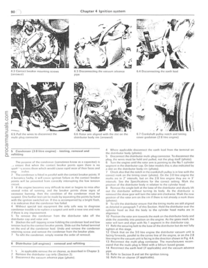 91
91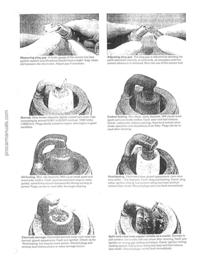 92
92 93
93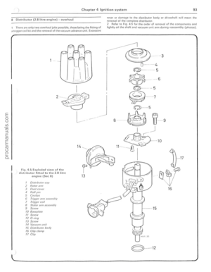 94
94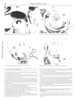 95
95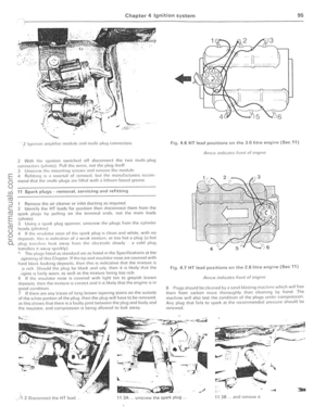 96
96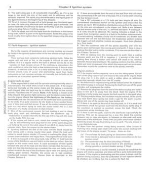 97
97 98
98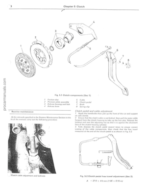 99
99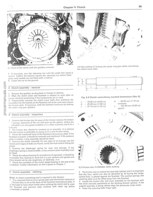 100
100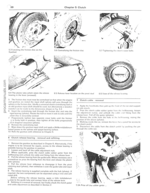 101
101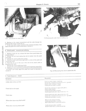 102
102 103
103 104
104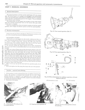 105
105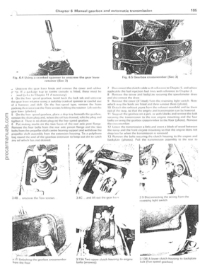 106
106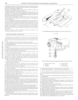 107
107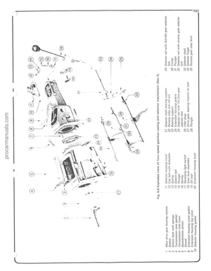 108
108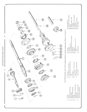 109
109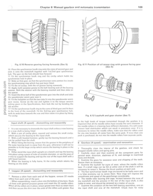 110
110 111
111 112
112 113
113 114
114 115
115 116
116 117
117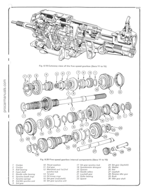 118
118 119
119 120
120 121
121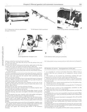 122
122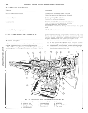 123
123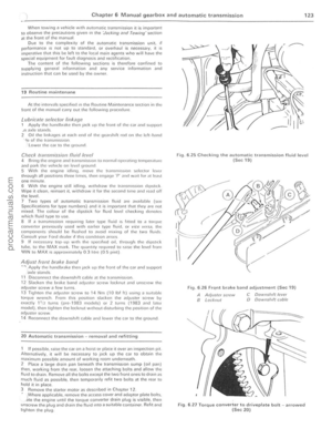 124
124 125
125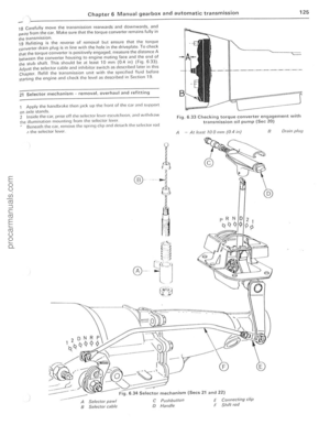 126
126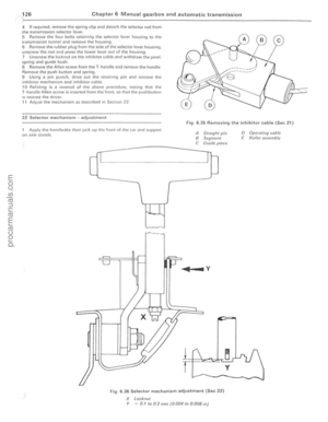 127
127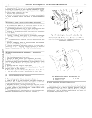 128
128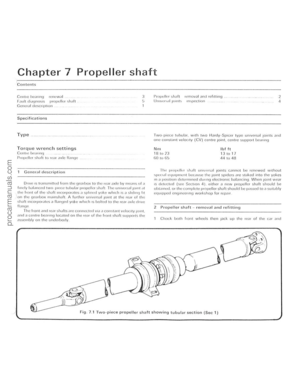 129
129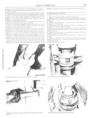 130
130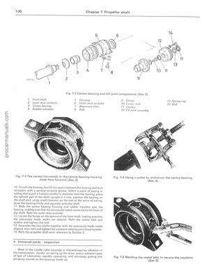 131
131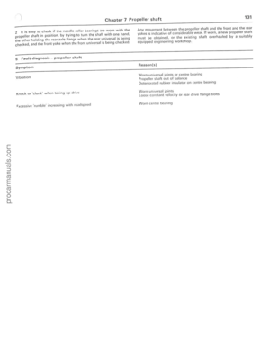 132
132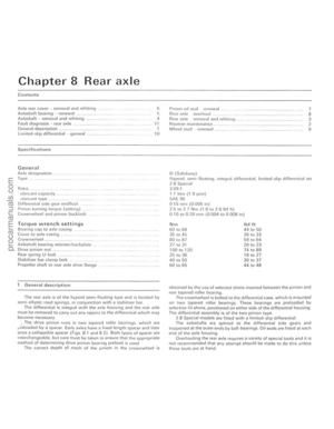 133
133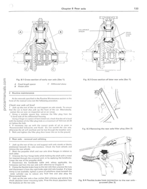 134
134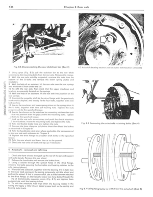 135
135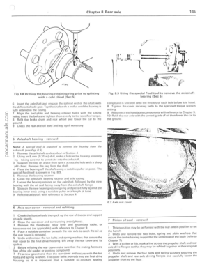 136
136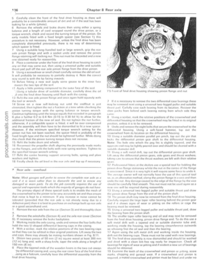 137
137 138
138 139
139 140
140 141
141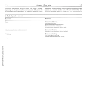 142
142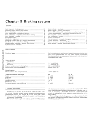 143
143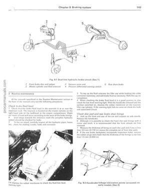 144
144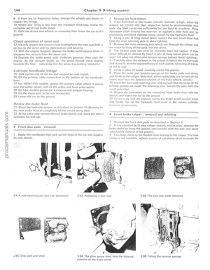 145
145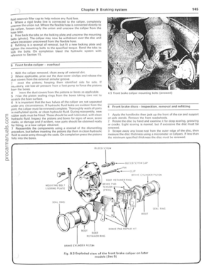 146
146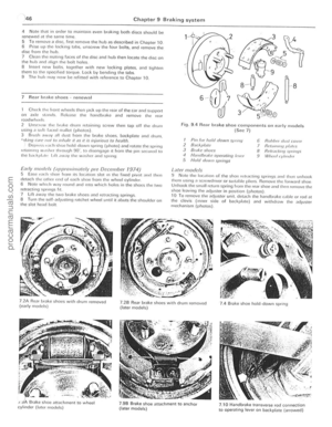 147
147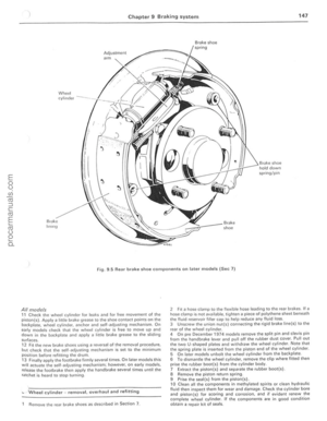 148
148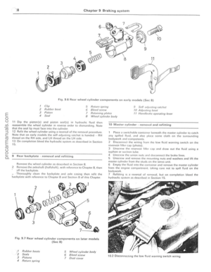 149
149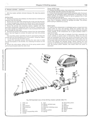 150
150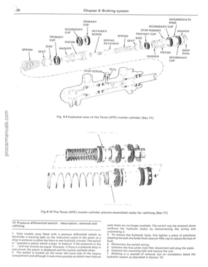 151
151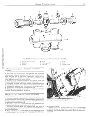 152
152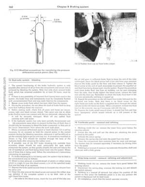 153
153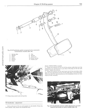 154
154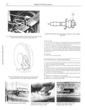 155
155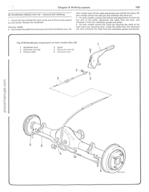 156
156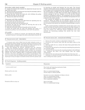 157
157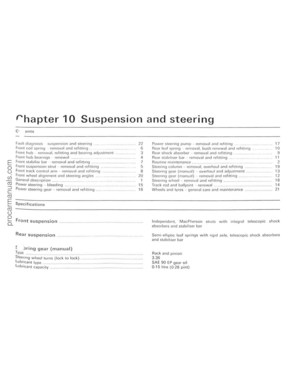 158
158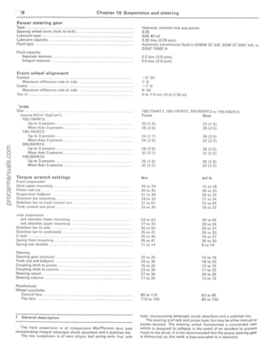 159
159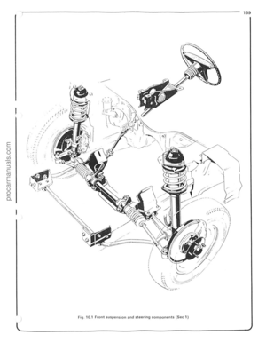 160
160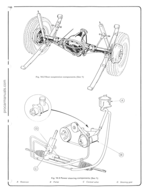 161
161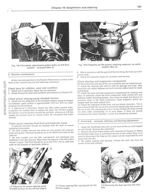 162
162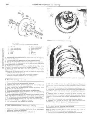 163
163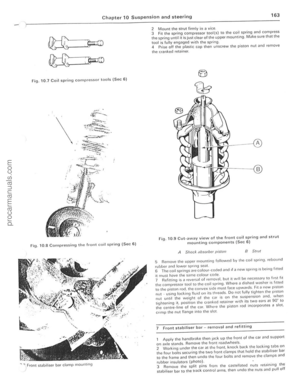 164
164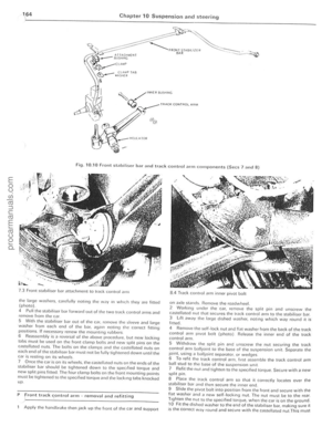 165
165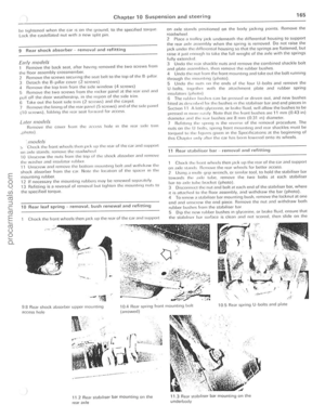 166
166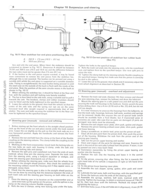 167
167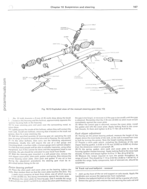 168
168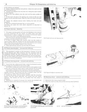 169
169 170
170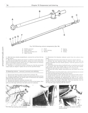 171
171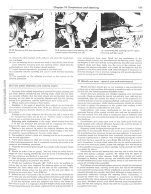 172
172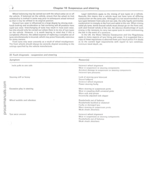 173
173 174
174 175
175 176
176 177
177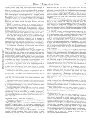 178
178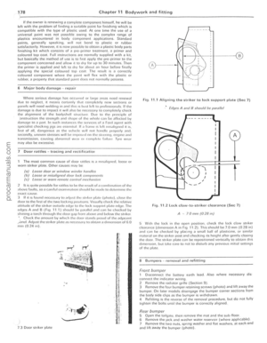 179
179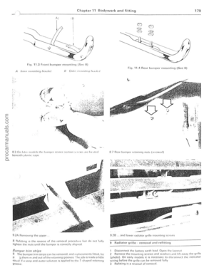 180
180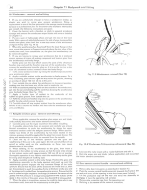 181
181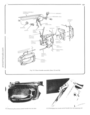 182
182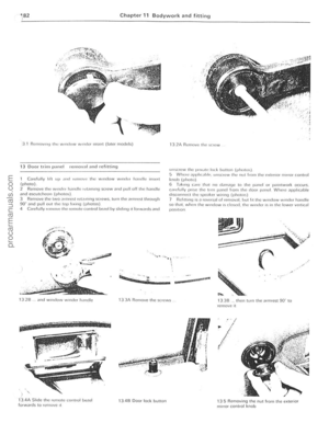 183
183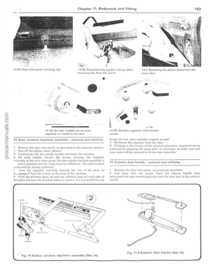 184
184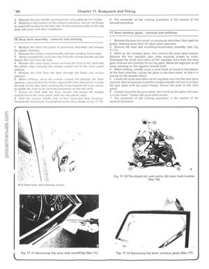 185
185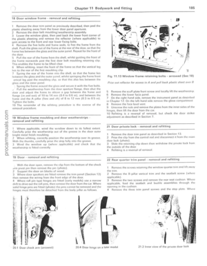 186
186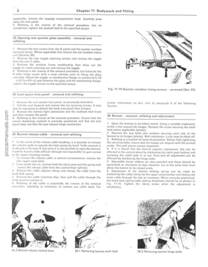 187
187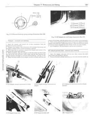 188
188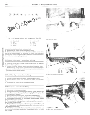 189
189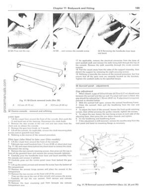 190
190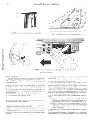 191
191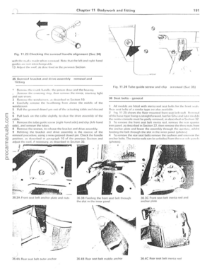 192
192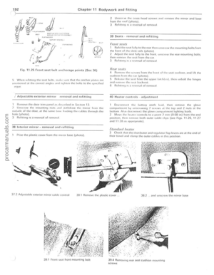 193
193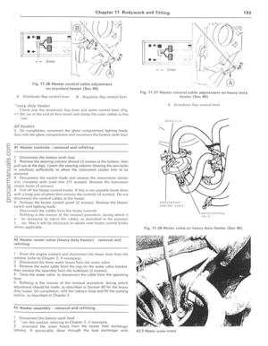 194
194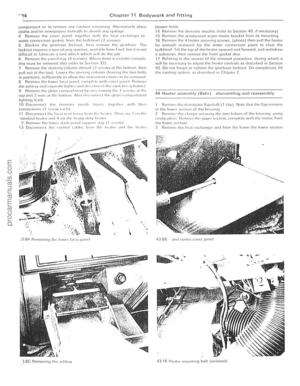 195
195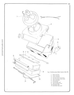 196
196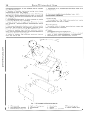 197
197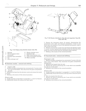 198
198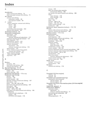 199
199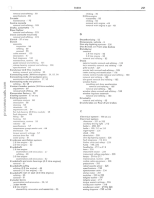 200
200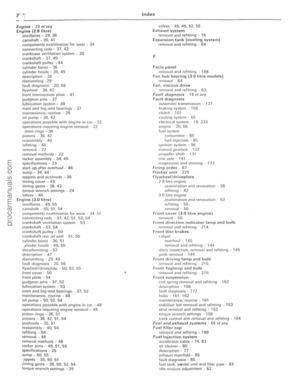 201
201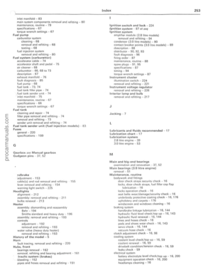 202
202 203
203 204
204