Page 137 of 205

5 C~rellJlly cle~n Ihe Ir Oll 1 01 the Im,ll d\"ve housinU ~s there will Ilroll<lhly be a considerilble <!IllOUni 01 drll and orl rl Ihe se<ll has heen leilkillg lo r a will")
Chapter 8 Rear axle 136 )
5 C~rellJlly cle~n Ihe Ir Oll 1 01 the Im,ll d"ve housinU ~s there will Ilroll
10lque w.ench. check and . ecor d the lurnrng IOrque of the pillion. On eally models lilted wllh ~ tl~ed longlh spacer (see SectIon 1) lI11S procedure is nOt neceSS
.,1 "\10 Ihe l ,n ,11 dllv!! hOllslnu unto! Ihl~h w'lh Ihe cas",o 13 Ilcfo1 Iho 1(';;1' "xlo p""nl1 fI.1IlUc ilnd on,:o "!I'"n hold sqll;,,,:ly wllh til" luol 0' wrench. 1~ SClew on " ncw s"II·I()c~"lll I1l1t IJIlIII Illl: (,ndllo,,1 ,s III~I dlll"n.llcd . II"", l'Uh h,n Iho nUL .1 1,;,,:11011 ill;r I"'h' whll" du":k"'!lII,,, prmO" lumlnu lor
fixed ICllnth type "nd I he nul should be tIghtened lurthor WhIle domu Ih,s cheC k Ih"l Ihe pimon lurnrnn lorque doos not mcre;;lse. 15 flelll the h",ke 1" ,,"d l O p up II 1\",:eS~lIly
P ReM axle -o verh;;lul
Note: Mosl ymilycs wtlf Ilft'h" 10 If.'IWW Iflt' comfllelC IC,ll ,Jxfc ,15 .1 111111 d II IS WOII! ,.II/IC' I/Ioll! 10 rf,SllliI",fc Ille UII/I 10 lel/t·w '''IV r/;/11I.Jycd 01 WOIII poll Is ro do tlw ,ob correclly Icquires Ifle usc 01 spccial <111(1 cxpellsive loofs willch tin' "'",u/lly of y"WY"'S do 1/01 h,lVl' The P"n1
, le lccl,v e Pol.l ) then IllS besllo Ilu.ch"se "II e~ch;lnHe bUIlt UJl le;;l. ilxl/! 01" Uoad secon (lh,lnd Uillt 1 Remove the rO;;lr "xle I,orn the ,:,1r (S(.'(;t,on 3) illld tha,oughly cleiln
,' . 2 Remove the a xlesh;;lhs (Sec lIon 4) "nd the;lxle ,e". covel (Secllon 6) . If rleceSS;;Jry remove lire !H" ke !liIckpl;,ws 3 WOlk,n!) inside IIlI! axle casUlU . undo .lnd .emove Ihe four bolts th" t hold Ihe IWO U'Shill>cd dlllerentl,ll be"rmg CilPS III the Cilsing. 4 W,lh a sc.iber. m
i h a dlffl!renliiJl casrny (Illd. uS"'IJ the lea, cove. 1;;Jr.:e o f thl! Irnal drrvo asing as" lu lc ,um. CDielully leve , Ihe (Mle.entlal asS(!mbly I.om the Ilna l d"ve housrng.
15 Froni I'll Im
7 1I'lls IIfJcess,lIY la ",move th e Iwo (hffelenlral casc l1'-'alll'gs Ihese
",.IY I,,, ",move(1 Ih:xl uSlnU " ulllvers,,1 two·leuged puliCI and sui!
111111'.1 1,.ld C"rfully uase e;lch bca'"'IJ Irom liS local ron . necovor Ihe ~IIOIII p.IO:k s hom hehmll e"ch be"rrnu nOlmU from whIch SId e Ihey (.,rlOr'! 8 thou!] a sCflhcr. m;;lrk Iho relative positions of Ihe crawnwhee l ilnd ,hU",,"rtl.,llrousinu so that the oownwhcelmay be f,tte d on rts origin al p"~H'OII. unless ,t .s to be lenewed. 9 Undo ,11", r enlo ve the eruht holtS thai secure Ihe crownwheello the ,hl,,,""'11:11 hOllS"'II. U S1nll a solt·faced h"n""cl. I,ll! 0\11 Iho cllJwllwhuci Irom liS locillion on Ih e d,ffe,enl,,,1 housin!) I 0 lJ~III\1 ;r sU I\(Ih l{) (i"unete. parallel pIn pmch. lap 0\11 Ihe pin Ihal Iud , ... Ilu, rI,'lcrelll,;,1 Illnial1 gea. Shilll 10 the dlftmrmll.11 housrnlJ.
NOLI! : 1 hu h"le 11110 willch thc peu Irts IS shghlly "'I>c.ed. lind the I>pl''''.'I'! "",1 may he IrIJhLly peelH)d over ;'Iml should he r.:!e;rned with a ·.u,I.II,I" ,".11111;1". ,tr,ll 11 th'''!1 a ... "It IIlI;t.11 dllfl. "'i> out Ihe drllelenli"l p"uon Ue", slr"h. 1.011 .Iw.ly tlr" d,lh;u!Oltl;r1 pinian ue,us. sido {leMS "lid IhruSI was hers; IA"'!l':,"" 10 ell::ure Ih"t the th,usl washe.s ",e lell wllh Ihe ir relative
liP,"" 12 1'",1"~"If)f .. ,1 Il1te.s (It Ihe ,)carrn!) CUllS. These mUSI nOl be used wllh new beallngs. 18Th" Ilnal UIIV(! assembly rs now drSl1lilllllod and should ho washed ,,,,,I d,u,d wrth PinU and uene'ill weal. If a c.ownwheel ami pinIon is .equllt.-d. a mated c.ownwheel and p inion muSI be II1I..,d and undor no
procarmanuals.com
Page 138 of 205
)
4 5 6
2 3
14
1 3 @~~-@
9 10
Fig . 8.1 0 ElIl>loded view o f the reM C1Kle {Sec 8)
I Axle housing 2 Diffcrcnlilll case (lJper lolle/ belJriJlg 3 DiffcIClltiDl r;ase Sillill 4 Crowflwhccl 5 GoskCI 6 COVCI 1 Drive (Jillion flange
8 Od seal 9 Drive pinion Ii/per follt·, bemiflg 10 Drive 11111;0'1 SIJaCCf _fixcd Icoglll 01 CQfl.1psllJlc II VI.IIIl Vilfve 12 O,ive {limon
M@
'¥' 16
.~
\\~
CIt I
~ I
~J
13 PmiOIl yea! 5".111 14 DlflClenliM C(lSf! 15 Sil/C yellr 16 O,flCfCIJ/ii!l pillion 17 Rctllininy filly 18 Axfcsh,1!1
137
procarmanuals.com
Page 139 of 205
. )
r'9' 8.11 Differential ClOsing and bCiHillU C
Fig. 8 .1 3 Removing tholockinu pin IrOtlllh c pinion goar shaft (Sec 8)
•
' • .'.....
• • I , , ,
I , , '<' • . ,
~( I
' ...... ,
~i9. 8.1 5 Checking tho d iff erential sid e gear ontilioal (Sec 8)
Fig. 8.12 RClll ovin!J the differential assemhlv (Sec 8)
'.
}
fig . 8 .1 4 Oiffercntiill cOIllI)oncnlS (Sec 8)
Fig. 8.1 6 Chocking the crownwheel and pinion backlash (Sec 8)
1
procarmanuals.com
Page 140 of 205

•
Chapter 8 Rear axle 139
ci,cumS«"Ulces mny only one pmt of the two be renewed. fnspect the dllfe,enti,ll pinions nnd side gems for signs of pitting. score mMks. Chipping nnd general wem. Obtain new gears as necessa,y . Inspect the th,ust washers lor signs of weM or deep sco,ing. Obwin new thrust wnshe,s as necessary. Once the pinion o il senl has been disturbed it must be discMded and a new one obtained. 20 When new pnrts have been obwined ns required. reassembly cnn begin. First lit the thrust washers to the side gems and place them in position in the differential housing. The ground side of the thrust washers IllUSt lace the side gC.Jrs. 21 Place tile thrust wilshers behind the dillelentini pinion genrs i1nd mesh these twO Oems with the Side gears through the tWI) ilpertores in the lilllerentlill housing. Milke sure they ilre diametlicilily opposite 10 each other. RO«l!e the clillerent'i11 pinion gears through 90' so brinUlI1\j them into line with the pinion genr shnlt bore 111 the housinlt 22 Insert the pinion genr shnft with the lock In!) p'n hole III line with the pill hole. 23 Usinu leeler 1),IU!Jcs. measure the en{lll(",t 01 ench s,de Be,,,. II the speclficd h\Jure IS excecrt"d. IU!W tl"u~t washlllS mu"t he olJt,uned
-omnlllie the a~~el)lhly ,lg,llll ,trld ht new thll,st wa:,lu'
suilahle dinmetci tul!c . cmclully lit the larg"r ti!per rollI)' benllll\) onto Ihe pillion shafl. The lar\ler dlilllleter 01 the be,lllllU !\lust be nex110 the pInion head
28 Using soitable diameter tubes. fit the two Wper roller bearing cones into the finnl dlive housing. making sure that they ale litted the correct way round. 29 Slide the shim and spncer onlO the pinion shalt and insert inlo t he final drive housing. 30 Relit the second and smaller diameter wper loller bea,ino onto the end of the pinion shaft lind 101i0w Ihis Wilh a new oil seal. Sefore Ihe senl is nctually fitted. apply some grense to the inner Ince between the two lips of the seal. 31 Apply n little jOinting compoond to the outer Ince of the seD I. 32 Using n tuhulilr dllft 01 suitable dinmeter, carefully drive the oil seal into the fillal (hive housinlJ. Make quite sore thnt it is lilted squarely and flush with the housinU. 33 Refn the drive pinion IInnge nnd hold securely in n bench vice. It II fixed lenIJth spncCl is Itlted. fit ilnd tighten the pinion nut 10 the spec ,lied lorque. If a collapsihle spnce r is f,tte d. follow the prOCedlHe
g iven in Section 7 paragraph 14. setting the pinion turning to'que to hetween 25 nnd 2.7 Nnt (1.810 2 0 Ihf It) which includes 0.2 to 0.<1 Nm (0.15 10 0.30 Ibl It) lor the ndriitional friction of the new oil senl II new hea,inns h~ve heen filted. logether With n li~e(l len(Jth SP,lCer. check thm the tOrlllllg torque is bel ween the limits just stmed. If not. a longer or shorter spilcer must he I,tted until the setting IS correct 34 Fit the healing cones to the cf,fierenllal houslIlg heallll(Js and carefully ease the housing Into posilion in the finill drive housmg 35 Relit the be,IIII'!J CilpS in thell originnl pOSitions. Srnc,ll n httle JOlntmg compound on the threilcfs 01 each cnp secuIII'O bolt nnd fit 11110 position. When ,111 low halts have bcen rein ted tiUhten these up in a (h"IJonal and progresSive milnne, to the speCi fied torque. 36 I I pOSSIble. 1Il00nt n dlnl in(licntor onu(Je so thnt the probe IS resting on one of the teeth of the crownwheel and determine the backlash hetween the clownwheel and pillion. The bileklash may be vMicd by elecreasll'\) the thickness of the shims bellind one beilling nnd incrensing the thickness of shirns behind the othcr. thus moving the crownwheel ;nlO or out ofmcsh as requi,ed. The tOt.llthlckness 01 the shims must not be chnn\)ed. 37 The hesl check the do·it·yourself owner cnn make to aSCerta", the correct meshinu of the crownwheel ilnd pinion is to smear ,I htt le engineer's blue onto the crownwheel and pinion iJnd then lot"te the pinion. The con1
COlleCI 100110 CO"t.1ct
_
t Heavy conWCl 0" huel. at 100lh !,leu Move p'",on lowa,ds crownwhcd u:.!:.crt:1 3nd c,ownwhuel towards p,n,on
.~\;!~" •. ,;.';,;,"",.,=,"--
l ' Fig. 8.17 CrownwheeJ and pinion setting chart (Sec 8)
, ,
, ,
"
procarmanuals.com
Page 141 of 205
 Chapter 8 Rear axle
crowllwh(lcl teeth. Refer to Fig 8. 7 where the corrcCl100l h paltcrn is shown, Also shown arc incorrec t loorh patterns ilnd the method of oi11<lining the conect patte")
·0 ) Chapter 8 Rear axle
crowllwh(lcl teeth. Refer to Fig 8.' 7 where the corrcCl100l h paltcrn is shown, Also shown arc incorrec t loorh patterns ilnd the method of oi11
9 Wheel stud -renewal
Chock the IrOllt wheels then lilck up the ,eaf of the Cill ilnd sUPPor! will> ilxlc S1
,I PU.lSS Or dllvc the wheel SlUt! through t he axlestwft /I;)n9c. 5 Clc
" 1',,11 tho slUd lully "'to Ihe lIan!)c "s"'\.1 ~ wheel nut ~nd wilsho,s as ,own III Fill . 818 ., neht the IHilke (hum ,11ld ,e~, wheel then lowel the eM 10 the
IUlld
10 lillli ted-slip diffc ronli"l-\.Ien er,,1
The IIllllwd·shp (I,fle,ent,,,1 's f,tled to 2 8 Spec,,,1 modl:ls ""d Its "';1111 purpose is to il,event wheef SPIll 01 the IIlsule ,ea, wheel when dnvin(l round bends or oul of l>emls w ith lull enOl/Ie powe, applied.
F i
ll. 8.19 Cutaway view o f the limited·slip differential (Sec 10 )
A Crowf!whecl /J fJ'{""I!/IIi,,/ carrier r: PIllIOII ue .. " /J $h .. ,{1 r fhlll.I'IIIII!llill",,,,II/,1C<.'S r Uukr IJ{;,I<.-((III """Ht'nll,,1 ,;,/1 IIf,'1 ) (; 1"111:1 I"a/(: ((III axle .
K Suit.' !I''""'' I. /lIIIHI IIII!/-I" 1M S,IIIIIII woIsl".:,s
)
i
F ig . 8.18 U sinll 11 wheel nut 10 pull il slud in to lhe ilJ(le
flonge (Sec 8)
Under these cond,tlons thNe I S il weiohttriln~IN 1 0 lilo oulslde wheel. ,111d lho deS'Bn of the standJIl1 (hlf(:relll,al is such Ihal all ,1dvmse I(uque con 110 ajlpl".:d 10 l11e Ills, de wheel ca"slIlII wheel ~pln, The l,lll ,W
procarmanuals.com
Page 142 of 205
Chapter 8 Rear axle 141
lings apm! and compress the clutch plntes. The nction is varinble. depending on the power npplied. so tlMt under full power the dIfferential will lock completely nlld full torque will be appl;ed to both
11 Fa ult diagnosis -rear axlo
Symptom
NOIse
"Clonk· Oil nccelera tlon nnd deceh:ontlun
,... Ilenka\Je
)
renr wheels . Under coasting or overrun conditions the differential will operate as a normal stnndard unit. The unit incorpora tes four different;nl pinions
Roason(s)
Worn axleshaft bearing Insufficient luhricant
Worn dlfferentinl houSIng bearings Worn crown wheel and pinion Incorrect crown wheel nnd pinion mush
Worn 1I. leshalt splrnes Excessive crownwheel nluJ pinIon bncklnsh
Pm ion oil senl Icnkrng ReM cove r gasket leaklllg 011 seal on
, , ,
procarmanuals.com
Page 143 of 205
(!dnl -removal .1nd refluing From m ake caliper -overhau l .. Front blake cillipCf -removal ;1nd Cl,UUl\1 .... ______ ._")
Chapter 9 Braking system
Fault rflnunosis -hrnking sys tem Foothrnk.c I)(!dnl -removal .1nd refluing From m ake caliper -overhau l .. Front blake cillipCf -removal ;1nd 'Cl,UUl\1 .... ______ ._ .................... . Front brake discs -inspection, ,enlov,,1 and rcl,!\in(J Front disc pilds -renewal , ....... _ ...... .. General description ..... .... ........ . ............ . H andb
Spcci/ic:ltions
Syste m type
I=rOl1t brakes ~c tt,ickncss :
Now ....................................... .
Min rmum.
Oisc fun ·out (ma~inlum including hub).
Mini'l1ulll disc pad lining Ihickness
Re ar brakes MInimum bfake shoe lining thickness.
Torque w re nch settings Caliper ....... ................. ................................... . Brake disc .................... . Backpl"te ........................... .................... .......... ................ .... .. .. .......... . Hydraulic unions. Bleed screw (ma~) .... Aecuf>Cfaling valve 'Clainel (Gi,ling)
Gonoral description
23
16
5 ,
G 3 1 18 20 19 14 15
Oisc brakes aro f;tted 10 Iho front wheels and drum brakes to the lea. wheels. Tho cable or cablo and rod opelilled handbrake oper:11es independently on the real wheels. A vacuum sorvo unit is fiued
" "tween the mastel cytinde. and loolbrake pedal to provide assistance 'en the pedal is depressed.
T he hy,aulic circui t is split frOnt and rear. Undel normal conditions
M,lSIC' cylinder -ove.hilul Milsle. cylinder -removill ilnd .e liuing . P.eSStue d,ffcrenliill swit c h -desoiplion .• e m ov,,1 and .el,ning P,essure ,educing valve · description. relllovill ilnd .er,llonu
Reil' i),lGkplilte · ,emov"r ilnu refining Hei!( i)r"ke shoes -renewal ....... .................. .............. . . Routine m"intenance ........ . ................. .
SlOp·lilmp switch - removal. re/rUlng and ildJustmcflI . Vilcuum servo unil _ description . Vncuum servo unil -rcrnovnl nod rcfiUing Wheel cylindcr -rcmovnl. ove.haul and ref'lIing
11 10 12 13 ,
7 2 17 21 22 8
Dlml hyd'i1ulic cif cuit. snlol Ironl i1nd rCilr WIth IlreSSU,e reducing v:llve in reil r ci.cui t on Iiller models. DISC I,onl brilkes i1nd self·ndjust illu rca .
(!rum brilkes. all wilh servo aSSIstance. Calrle or c.,blc .1nd rod operated handbrake on rear l)f"k es
12 .7 mm (0.5 in) 11.4 rnm (0.45 in) 009 nlln (0.0035 in) 3 .0 mm (0.118 in)
1.5 mm (0.059 in)
Nm 471068 41 1046 271031 71010 10 491062
Ibl It 351050 301034 20 to 23 5 to 7 7 36 to 46
both ci.cuilS operale in unison. howeve •. in the event of faIlure o f one circui t Ihe lemaining ci.cui l will p
procarmanuals.com
Page 144 of 205
 Chapter 9 Braking syste m 143
2
Fig. 9.1 DU<lI linc hydn.ulic brnke circuit (Sec 1)
1 2 Fron! br,)k(1 disc ,1nil c<1IijJ~'f M,lS/IH cylinder and I/uid resefvoir 3 V,KIIUIn sClva unit 5 ReM d")
) Chapter 9 Braking syste m 143
2
Fig. 9.1 DU
1 2 Fron! br,)k(1 disc ,1nil c<1IijJ~'f M,lS/IH cylinder and I/uid resefvoir 3 V,KIIUIn sClva unit 5 ReM drum brake 4 Prcss1ltc (h!fetcH/i.)1 wi/filing swi/cl!
2 ROlltine maintenance
Al III<, u,h!lvals speClficed in the Routine M
Check hrilke fluid Ivvel 1 CI",<;k 110.11 Ilw hrake thud )"vcl in the reselvoir is .1, or nc." lhe 1Il,,~i"'lI'" ',,,10k The ,c~;cr\loi( is localed on the master cylinder on the nghl-hillld sule 01 the IJulkhead III the cl1uine cOIllpnnlllCII!. SliUht Va-"I,ulls of I"vel Will occur ilccordlfl!) to the wear ollhe II/
2 ·'h tim cm rnlsed. c,lIe1l1lly inspect illl the hydraulic pipes. hoses ;lnt. .. ,lions lor chJlmg. c'ilcks. Illilks ilnd corrosion.
2.4 ;-.-
uejJ.es~ the rubue' membrJne to check the fluid low level
Warning IrUht
3 To top up the fluid unscrew the fill er cap whrle holding the c,lhle connector sWtionar y. and add brake lIuid ns necessJr y. R efit the cnp on completion. 4 When checking the brnk e fluid level it is n good practice to also check the low level wnrning light With the hnndbwke rele
Check disc p<1d and rear bwke shoe linings 5 Jnck up the Iront nnd rem of the Cilr nnd support all il xle stands,
Re leuse the hilndb'
,emoved. 7 Mensufe the thickness 0 1 lining on e
thnn 1 .5 mm (0.059 in)
Fig. 9.2 Handbr a ke lin k ag e lubrication points (arro\Ncd) on early models (Sec 2)
I .
i
! j..
1:
, ,
procarmanuals.com
 1
1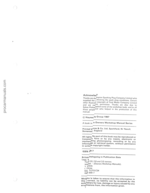 2
2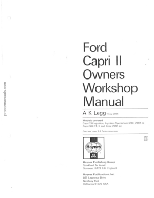 3
3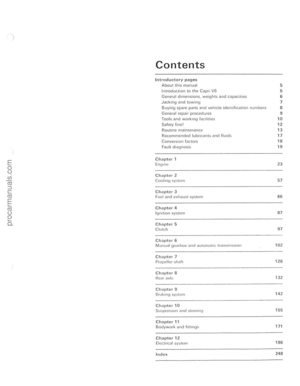 4
4 5
5 6
6 7
7 8
8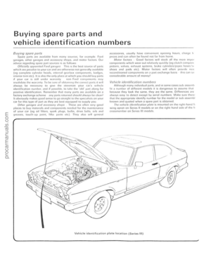 9
9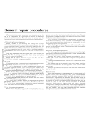 10
10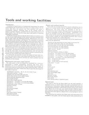 11
11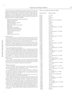 12
12 13
13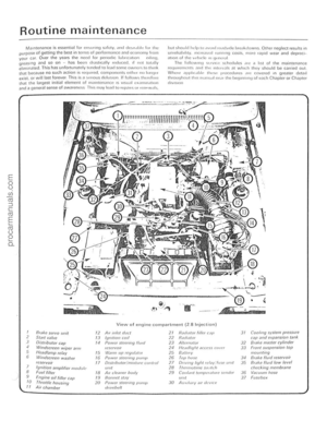 14
14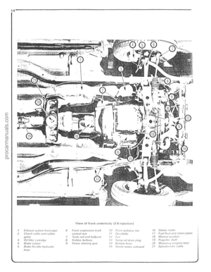 15
15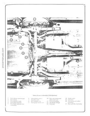 16
16 17
17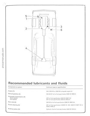 18
18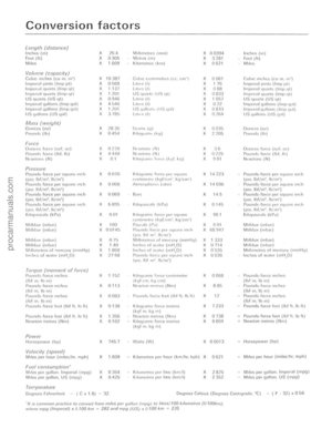 19
19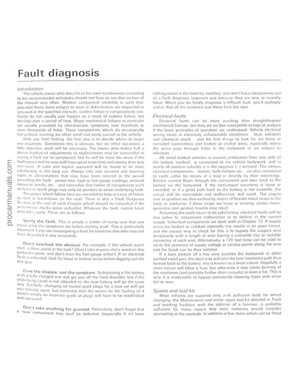 20
20 21
21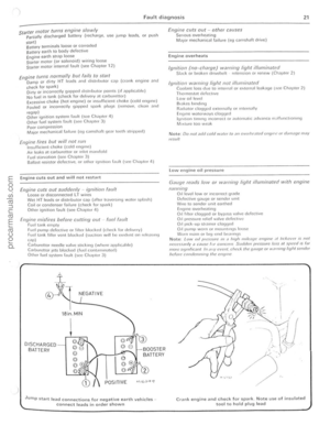 22
22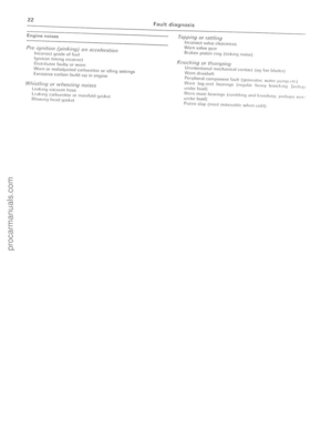 23
23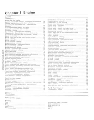 24
24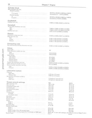 25
25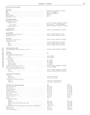 26
26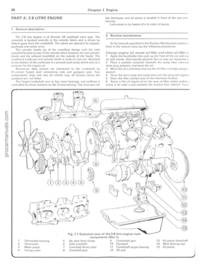 27
27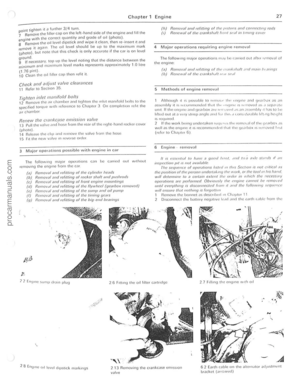 28
28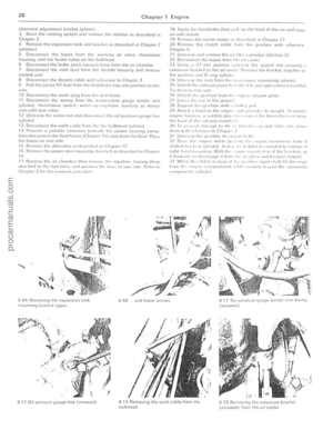 29
29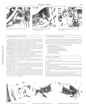 30
30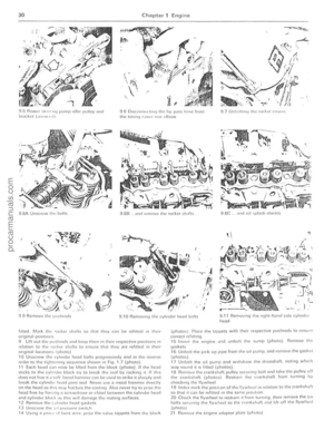 31
31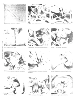 32
32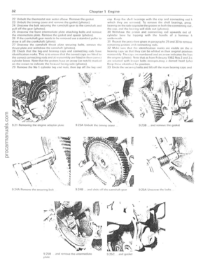 33
33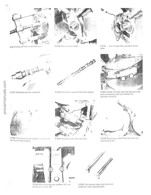 34
34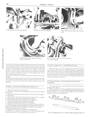 35
35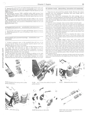 36
36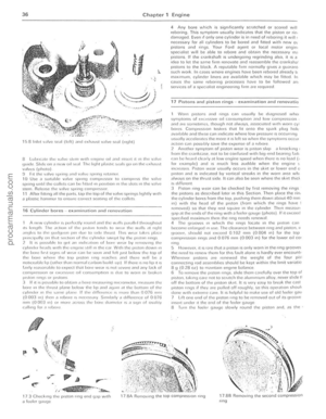 37
37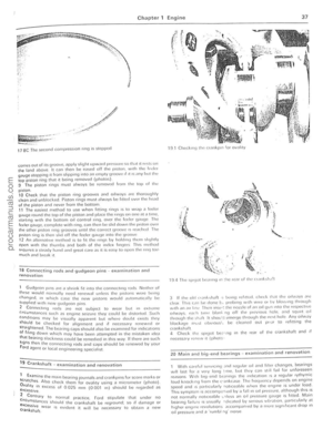 38
38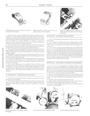 39
39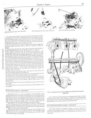 40
40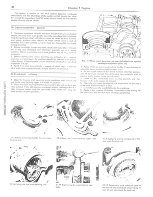 41
41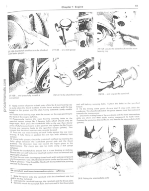 42
42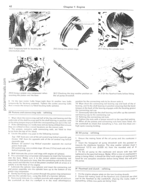 43
43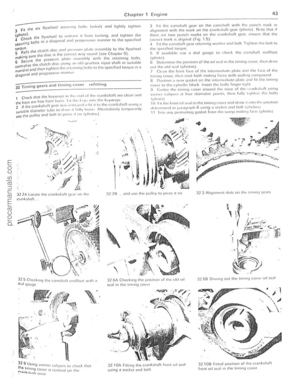 44
44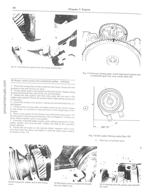 45
45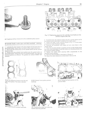 46
46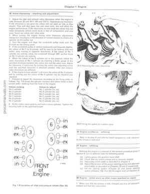 47
47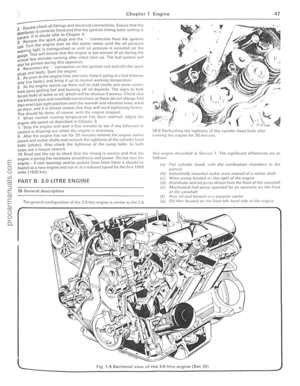 48
48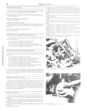 49
49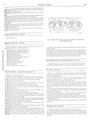 50
50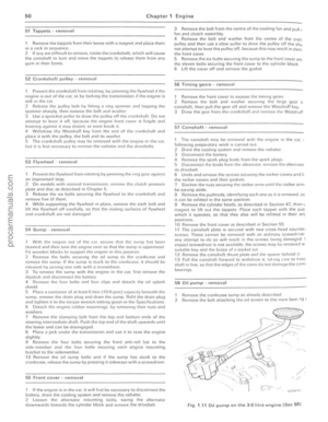 51
51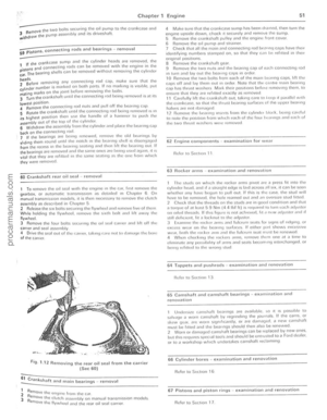 52
52 53
53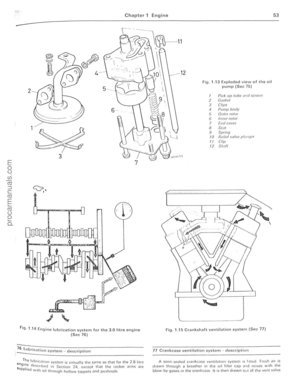 54
54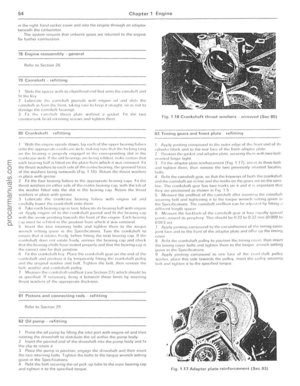 55
55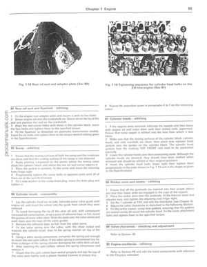 56
56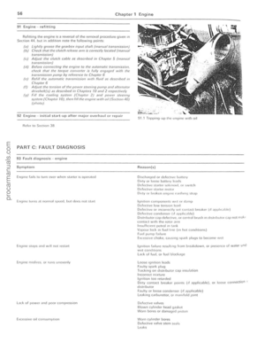 57
57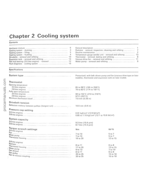 58
58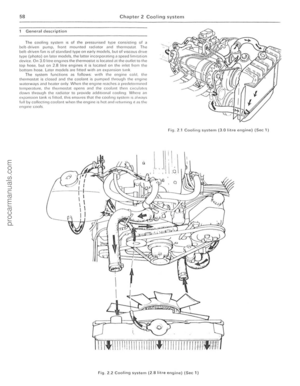 59
59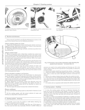 60
60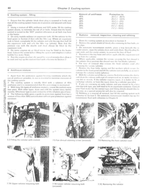 61
61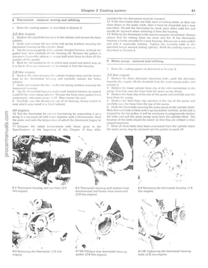 62
62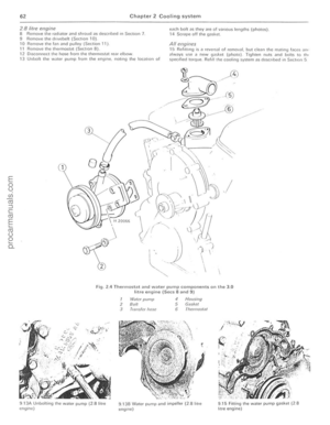 63
63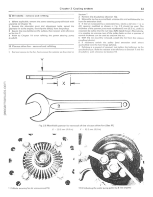 64
64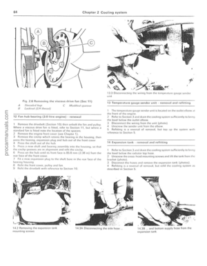 65
65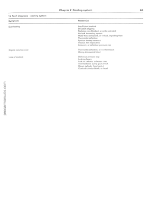 66
66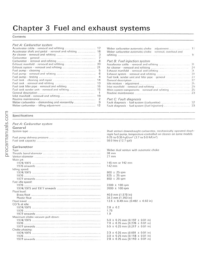 67
67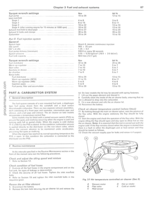 68
68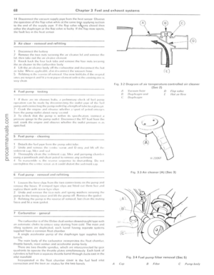 69
69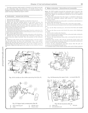 70
70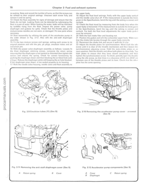 71
71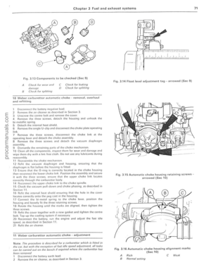 72
72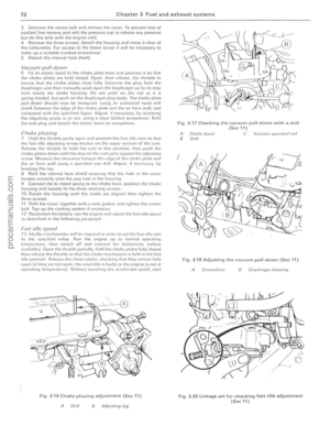 73
73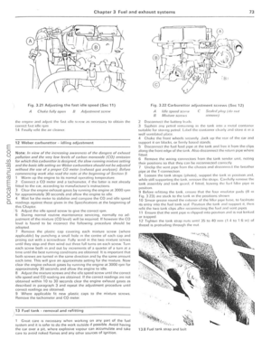 74
74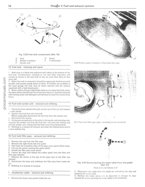 75
75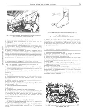 76
76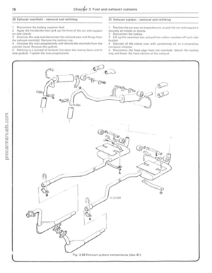 77
77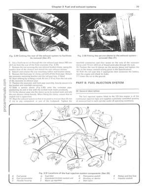 78
78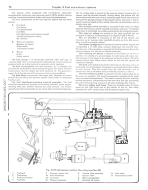 79
79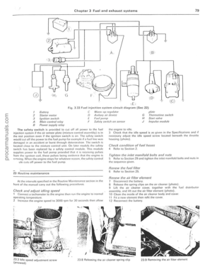 80
80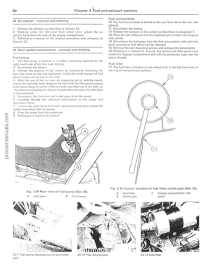 81
81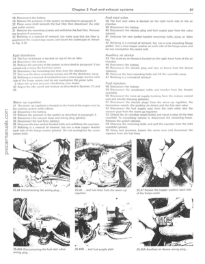 82
82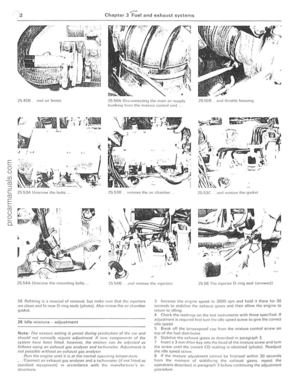 83
83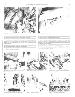 84
84 85
85 86
86 87
87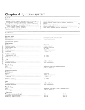 88
88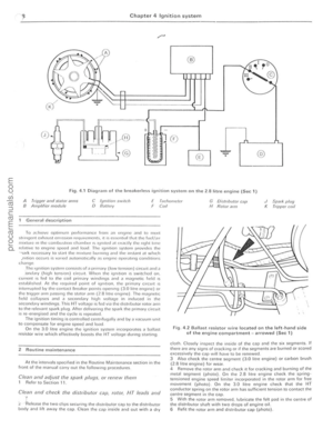 89
89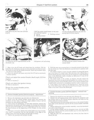 90
90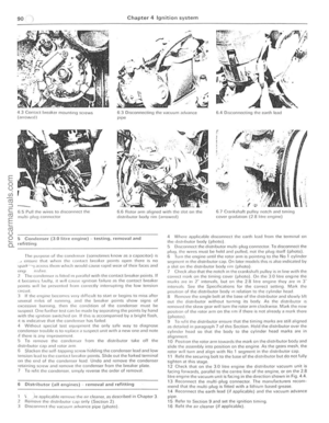 91
91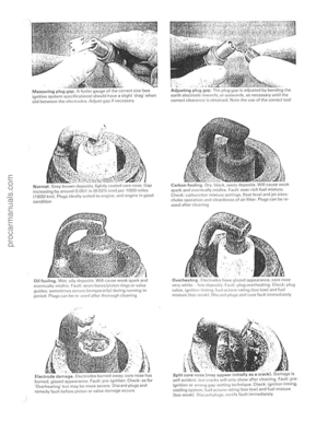 92
92 93
93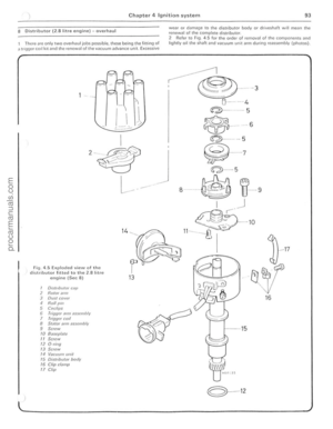 94
94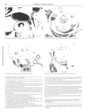 95
95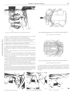 96
96 97
97 98
98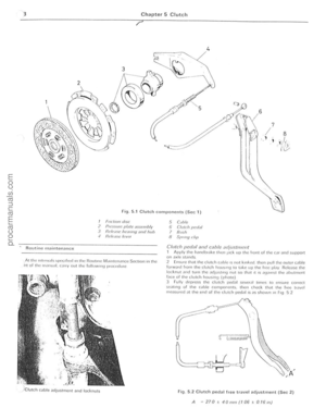 99
99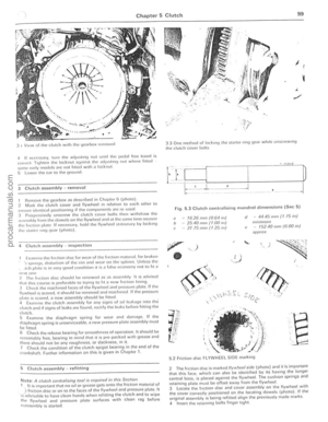 100
100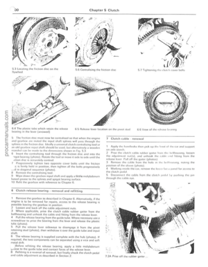 101
101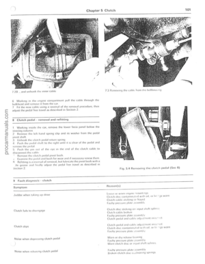 102
102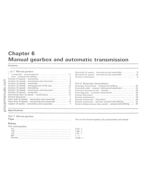 103
103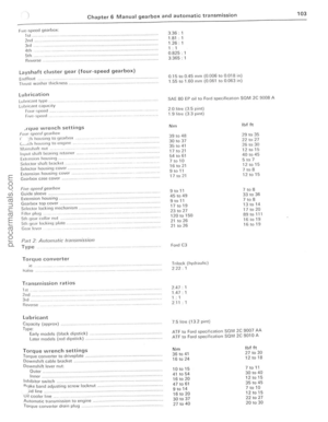 104
104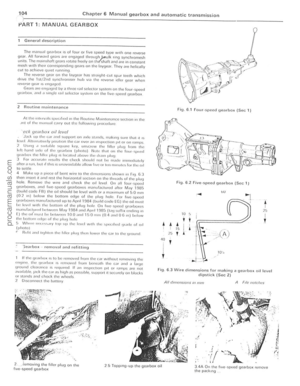 105
105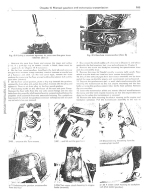 106
106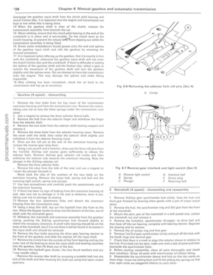 107
107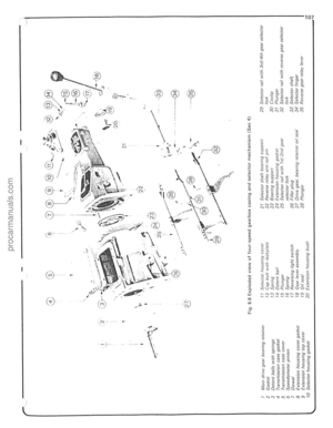 108
108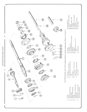 109
109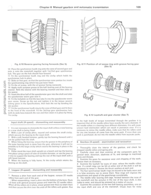 110
110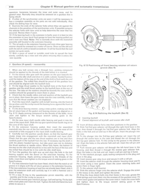 111
111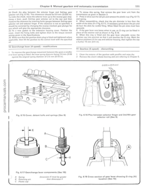 112
112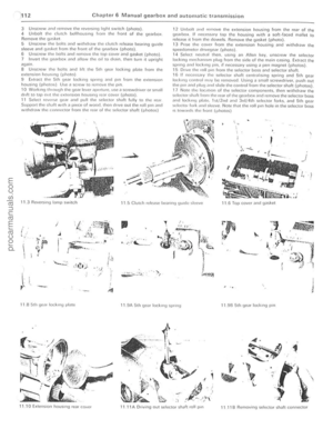 113
113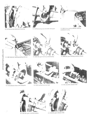 114
114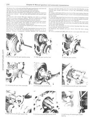 115
115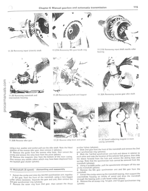 116
116 117
117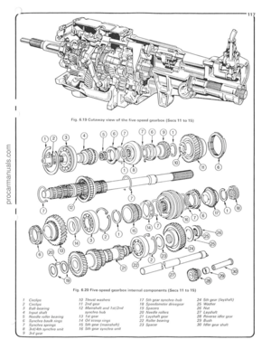 118
118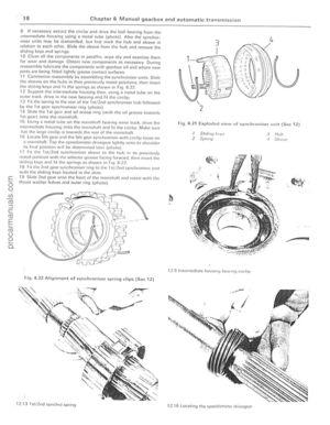 119
119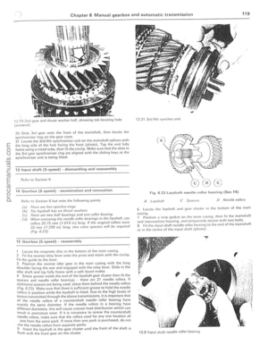 120
120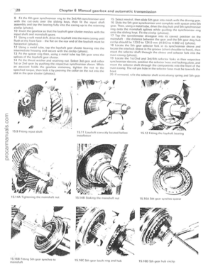 121
121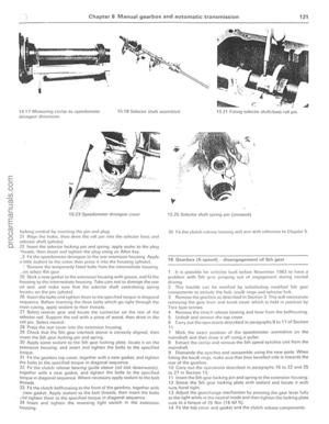 122
122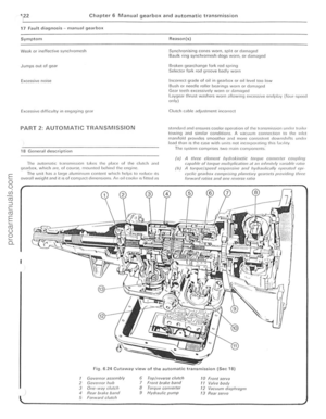 123
123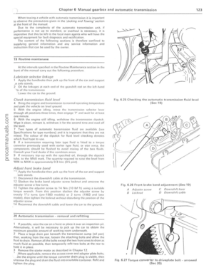 124
124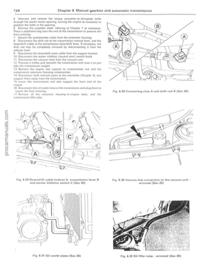 125
125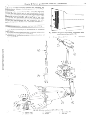 126
126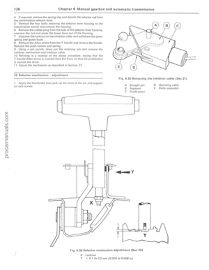 127
127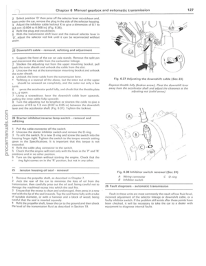 128
128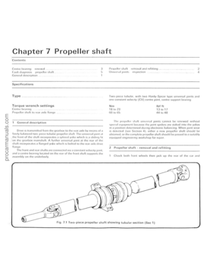 129
129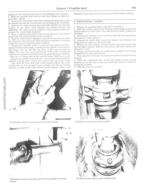 130
130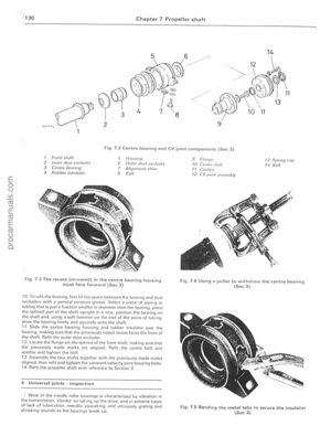 131
131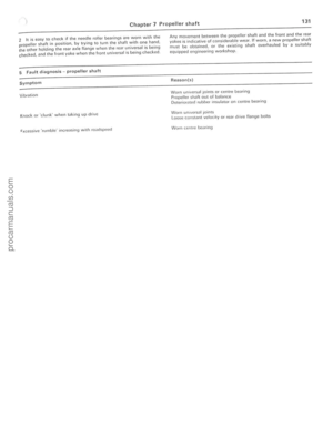 132
132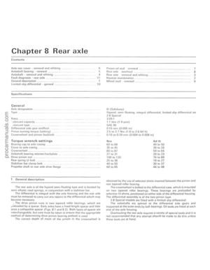 133
133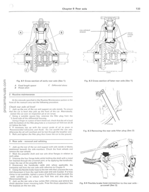 134
134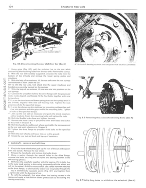 135
135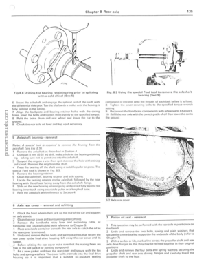 136
136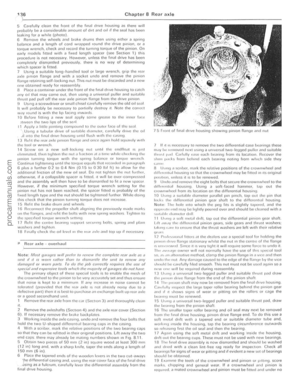 137
137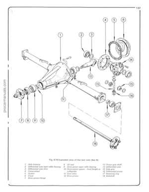 138
138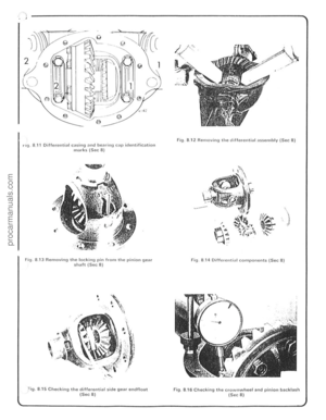 139
139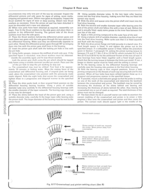 140
140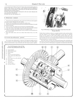 141
141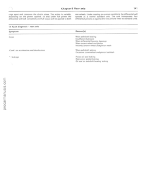 142
142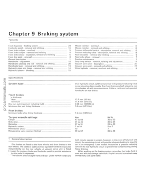 143
143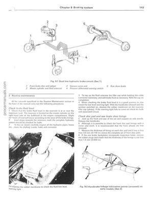 144
144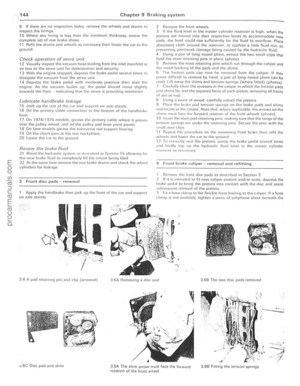 145
145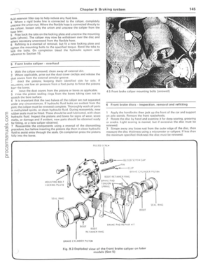 146
146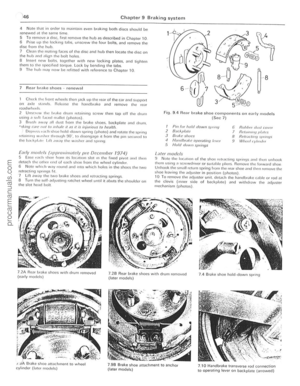 147
147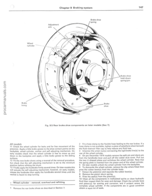 148
148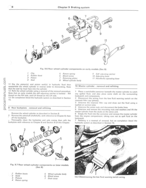 149
149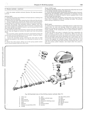 150
150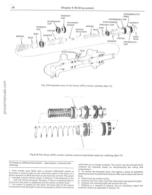 151
151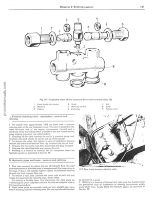 152
152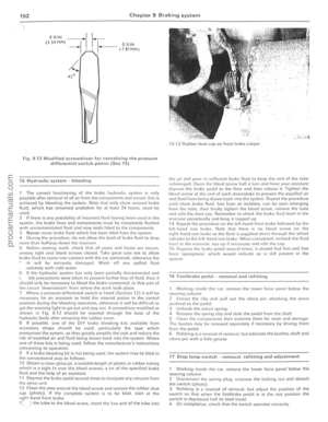 153
153 154
154 155
155 156
156 157
157 158
158 159
159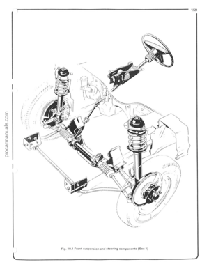 160
160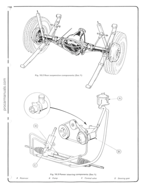 161
161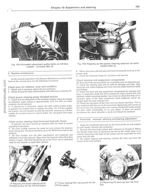 162
162 163
163 164
164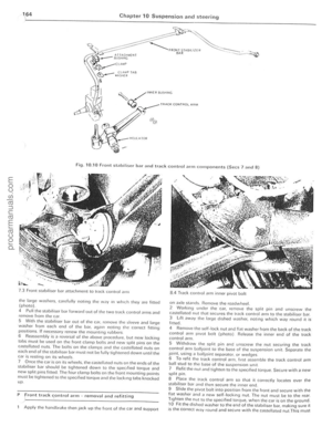 165
165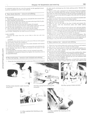 166
166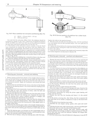 167
167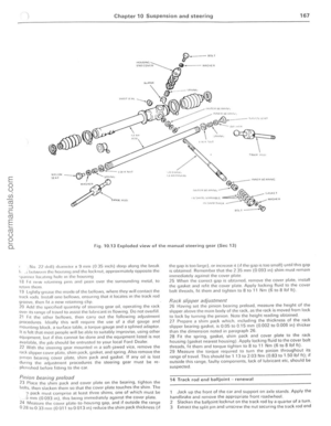 168
168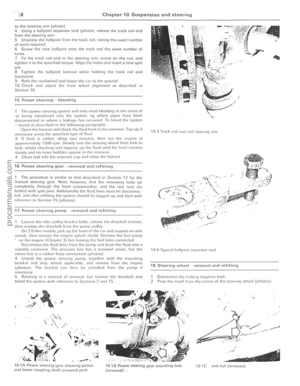 169
169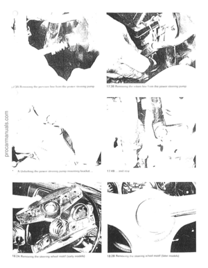 170
170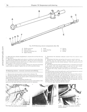 171
171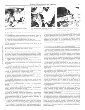 172
172 173
173 174
174 175
175 176
176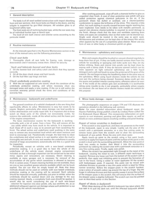 177
177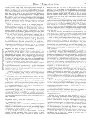 178
178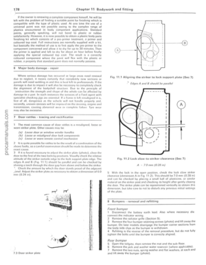 179
179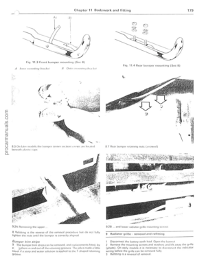 180
180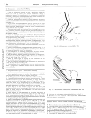 181
181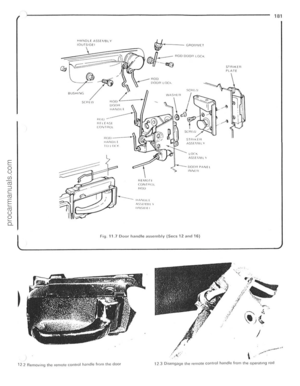 182
182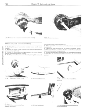 183
183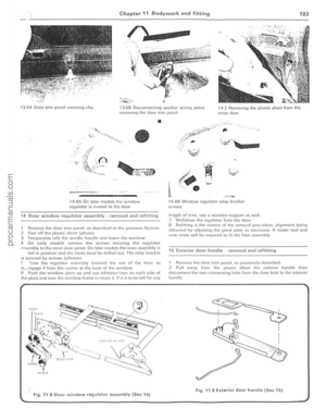 184
184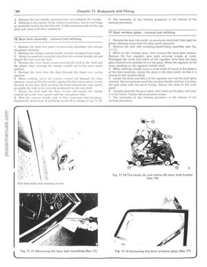 185
185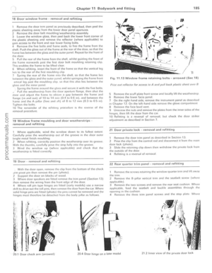 186
186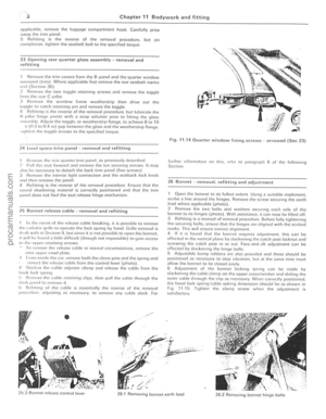 187
187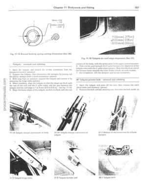 188
188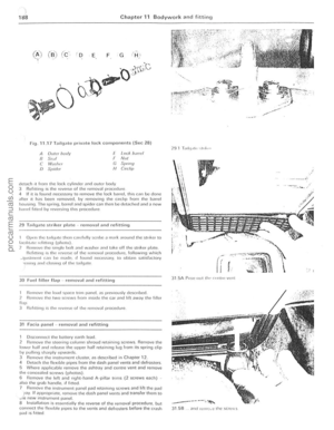 189
189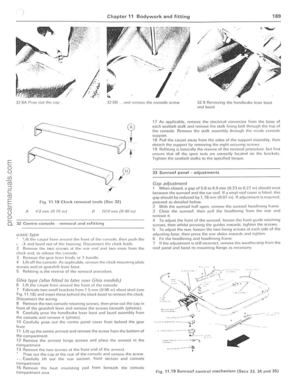 190
190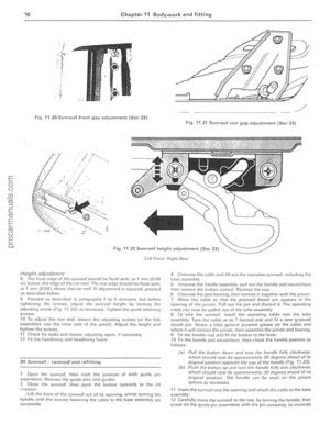 191
191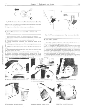 192
192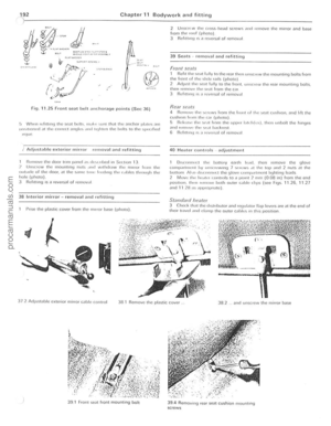 193
193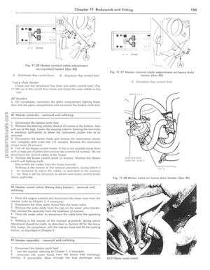 194
194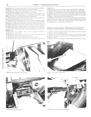 195
195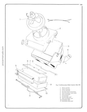 196
196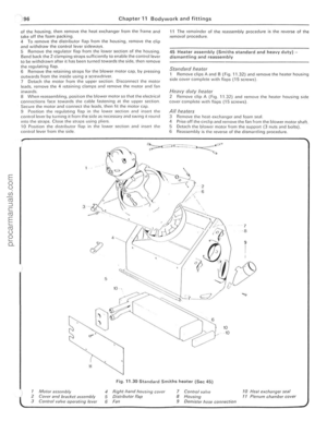 197
197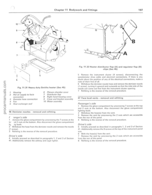 198
198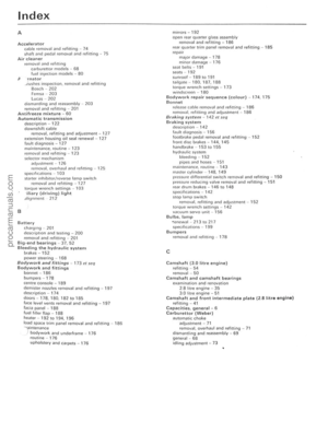 199
199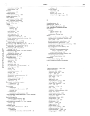 200
200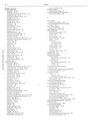 201
201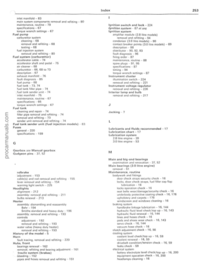 202
202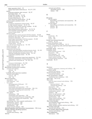 203
203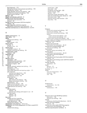 204
204
4 5 6
2 3
14
1 3 @~~-@
9 10
Fig . 8.1 0 ElIl>loded view o f the reM C1Kle {Sec 8)
I Axle housing 2 Diffcrcnlilll case (lJper lolle/ belJriJlg 3 DiffcIClltiDl r;ase Sillill 4 Crowflwhccl 5 G")

r9 8.11 Differential ClOsing and bCiHillU C<lP identificatio n nrks (Sec 8)
Fig. 8 .1 3 Removing tholockinu pin IrOtlllh c pinion goar shaft (Sec 8)
•
• ......
• • I , , ,
I")
