Page 89 of 205

A higgcf \",,(I stiltor ,1(111$ 8 Am/Jlt/icf modufe C Iylll/ion S")
Q
Chapte r 4 Ignition system
®
0 -
-@ @
Fig. 4 .1 Diagwll1 of the hre(lkerlcs5 ignition syslem on the 2 .a litre engine (Sec 1 )
A higgcf ",,(I stiltor ,1(111$ 8 Am/Jlt/icf modufe C Iylll/ion SWJ/i:lr o BMI£'fY E 'm:lmJIIl"/l:f F COIl G D is/nUll/a , c.-,/! H Ho/or .11111 J 5p,1fK, IJ/ug K 'fi''l)CI co,1
Gcneral de:;criptio n
To ;l(; h.cvc OP\I"'U'" pCl lo.mancc hom an CIl(lUlC ;\Old In mCCI ~1""\JCUt e.h,1u~t C""5s"m r .. '
- '),uk nece ss1Hv to start thc: Illlxlu1I1I""!1 ;md the In~t;"l\ ill wh'ch ,union occurs IS Y;lrI"d auwnJ.1tlC;lllv as ""\line Opet(lt'U g cOl1llot'I)I1 $ d';1r1ge The ''In,tlon systc)t1I COIIS '5 15 01 a PWll;IIV (low tc n slon) CUClnt ill"t J ondarv (1I1g11 tens,on) Cirelnl. Wlwl I he '\lnI\IOIl IS SWltchlid on. CUlrellt IS fe d 10 Ihe coil p r;111;uv wirl(hllUS nnd i1 IIHl\l11Ctic f,p.ld IS cst~lbhshC(1 At Ihe r equired 1)0"11 o r 101l1\10n. the pri"':Irv CItCl/lt IS Ifl tcrruptClluV the conlnct hfenker POUlIS OllCflmg (3 .0 hire e"gI01(I) or the \l'g\le. tJrfllpasslt'g the s tator ;11111 (2 8lrt,e enUn .e) The milunCIiC
f 'eld collilpscs :Ind il 5tlCOndntV hi~h YOIIIl~~ In 'nduced i n the se~ond,1rv win(lin\!s. This HT volt:lUc IS te d via th e d'SH ,IJUtor rOIOI :Iun
1 0 the lelevllllt spnrk plu~. Alter dcllvenng the spar k the pmnnrv cirC Uli
I S re-energised lind the cvcle .s rep-Cillcd. The igni tion t iminu '5 Controlled centro lugllllV JnO UV II vacuum IHl II t o compensme lor englflC speed ,1no 10lld On Ihe 3.0 litre enginc the i~l1;lion s y Stelll II1corporales a b,1ita $1
resistor wire which effcctively UOOSIS th e HT volw~e durlllg SHul,ng.
2 Routine m aintenance
At Ihe in tervals speCIfied in tl w Rouline Ma;ntenance section in the fran I of the nl;Jnua l cJrrV out the foll owmg proc edures .
Clean and adjust Ihe spark plugs. or renew Ihem 1 Refer to Sec tion 11.
Clean ofld chec k fhe distribulor cop. rolor. NT leads illlr/
t. Re lease the twO chI'S securmg Ihe (h Slllbu101 cap 10 Ihe d'5111l1utor uodV and I, ft away t he ca l) . ereJn Ihl;l C:lP inside and oul wilh a dtv
---we F
Fig. 4 .2 (J"II(ls t resistor wire locilted on tho left·h'Hld side of the ongino compartment -urrowed (Sec 1)
clO lh . Closely inspec t the ",side of thc cap and the si. segments. It there are any siUns of Cr<1Ckulg 01 ,f the segmentS are bumcd o. scorl;ld e~cessivelv the Cal) will h ave to be renewed.
3 Also Check Ihe cenlrc segment (3.0 htr a en\]ine) or carbon brush (2.8 IIlre engine) f or wailr. 4 Remove the rOIOI arm i1nd check 1110 ' cra ck ing and burning of the melal scgmem (pholo). On the 2.8 h ire en gin e check tM Sp
S W'th Ihe . o to r aIR. removed. lub.icate the felt pad in the Centr e of the distfluutor sh ah wilh twO drops o f enyine oil. 6 Rel;lthe rOtor arm and dt$Uluutor cap (photo).
d
procarmanuals.com
Page 90 of 205
 Chapter 4 Ignition system 89
2,4A ncmovllI\J the 010 rum (28 hire enuino) 2413 The engine speed tllnnel 011 tho ,oto. :lIm (2_8 litre ename) 26 Secul;nn lhe dl surUlllor cap wilh Ihe sp.;ng clo")
) Chapter 4 Ignition system 89
2,4A ncmovllI\J the ' 010' rum (28 hire enuino) 2413 The engine speed tllnnel 011 tho ,oto. :lIm (2_8 litre ename) 26 Secul;nn lhe dl surUlllor cap wilh Ihe sp.;ng clops (2.8 "lie engme) A Swing C fail/lillY COIlf.lCt n MQving CQII/act
27 ChcckUl!J Ihe HT tcad le.min;!ls on the (hSlllhutOf 1:.111 2 .8 11I"iliol1 COlt and WlIlIl!! 4 .2 Remov,ng I he COlllaCI h.eilke. low lenS 'OIl le,lds
7 W"H) o;iean the HT Itlad,; llm! check Ihc'" 10' (;onll'[IOI1 Pull the 1(';'Ids homlh!) dl~l"h"10f Cilll one;H IIOSiOIl "W,IY . Ien .eln the IC!1ds (I)hoto). 8 Glc,," Ihu '!jll'l,on cOIl lowe. ;md check the HT le,,(1 ;IS p.eYiously . ,scJllled (photo)
Check .1nd Mljus( (h£! cont<1c t brc<1ker dwell "flyle (3.0 fi/re
engillt!) !l Ruler to S
Check arid adjllst Ihe ignilion timing 10 Rcler to SectIon 9 .
Reflew /lit.' conl,1CI breaker points 11 Reier to Secuon 4 .
3 CO I1\aet ureaker points (3.0 litr e er>gine) -adjustment
1 Remove thO dis touutor cap and ro tor afln (Sect ion 2) 2 Gentlv I)rrse Ihe contact ureaker points open and e~an\ine the conditIon of Iherr faces. II they are .ough. pined o. dlfty II WIll ue IlCCeSSi\'y 101 new paIn IS to be fined. 3 If Ihe pOInts ale sallSfaclory. Or have been ,enewed. measu.e the gap Uel ..... een the points with feele . gauges. by turning Ihe Clankshaft unlll I',e heel 01 Ihe ureake. arm is on a high poinl of Ihe C
I If Ihe gal) IS IIlcorrCCl, slacken Ihe contact plale SOCuflllg screw(s). , le n "lserl a soewd"ve. ;nlO the sial p.ovided al Ihe edge of Ihe COntaCI ptalH and move the plate unlli lhe gap is corrcc\.
5 Tlghlen Ihe sClew(s) and .echeck Ih e gap.
6 Rein the .010. ;"1IU1 ensurIng th,lt II IS cOflectly located In the sial at
I he lOp 01 the carn Relltlho d'SI"lJuIO' CilP and .elain III IIOS;llon wnh Ihe Iwo clIps . 7 On 1110de.n el1gll'os a mo.e ,1CCu'ale mel hod 01 seHIIlg Ihe I>o;nts Hal) .s by means o f a dwell me lel . NOI only docs 111110 l11elhod give a
IHL'Cisc 1)0 .. 115 gap I)UIII also evens oul ally v,llta llons 111 Un,) cnused by wear "' I he dlst"'lUtor sh ah 01 uushes 0' dlHCf()nce s HI any 01 the heIgh ts 01 Ihe Cil'" peilks 8 The dwell allU1c IS Ihe numt)C. 01 deglee s th, ounh winch Ihe
dIstributor cam lUI liS dUring the IlCrlod betweell Ihe ",S\ilIlIS 01 closu
a dwell mele' connecled III aCcor d,lnce wllh lh. } maker's II'Slfl.r.;I'OIlS 9 II Iho angle IS nOI as gIven 111 the Spe<:.hcatl ons. ildluS t the po",ts u~p If the dwell annie's 100 ,,,'ge ,ncrease Ihc IJO'''15 9,111. II th e dwell [lI1gle ;s too small . 'educe Ihe points Uap
4 Conlilct hre[l ke r points (J.O litre engine) -removal and refitting
Remove the d'SlflbutOi C"P and 'OlOr arm (Secl;on 2) . 2 Slacken th e self·tappiu\J sc.ew which secllres the condense. illld low lension lead s 10 the conl,lel ureake. ilssembly ilnd slide oul lhe fo.ked cable telfllll,al;OnS (phOIO). 3 Undo and .emovc Ihe Iwo screws whIch secu.e the contact b.eake' uase pll'Ie 10 thO d'SlflbulOr ilfld hit off the cUlltact b.eaker assembly
(phOIO) .
4 Befo.e IClilling the conlact b.eake. assemhly. smear Iho dlstrluu to . cam wllh a trace 01 g.ease 5 FIt I he conlaC I 1)I(,ake' and its cl,Jlnping sr.;.ew~. but do nOI fully I;ghten the sc.ews \lnlll Iho contilC I b.eake. !I,111 h;IS u een adlusled as descflbed In Sec tion 3
6 R ell l th e rotor "fin and d.stflhuw. cal ). ""'1I"'~1 tI,e IWO clops 10 secure lhe cap.
"
, ,
: I
procarmanuals.com
Page 91 of 205
 Chapter 4 Ignition sys tem
.
. =-,,\":.
:f/~jI
iJ -~
, ..
k~
~
<1 3 Contact hlcnkc. mOUIlJrrlO ~CH)WS (,lrrowcd) 63 Dlsconncclinu the V<lClJlHll .1dvllllcC ppe G.4 OlsconneClill\) I")
90 ) Chapter 4 Ignition sys tem
' .
. ' =-,,":.
:f/~jI
iJ -~
, .. '
k~
~
<1 3 Contact hlcnkc. mOUIlJrrlO ~CH)WS (,lrrowcd) 63 Dlsconncclinu the V
-
(
/
r
I
I
I
,
. '. f
'1,j , , , ,
65 Pull tile wires 10 rhSCOlll1CCl the mull"I)I.,\) COlll1eClor 6.6 flOIO. arm al;\jncd with the slOI on t he d,strlhutor hrnly rim (allowed) 6 .7 C'ilnkshall polley nOlch and Imling covel gr,1(lahOn (28 hIre cn!l'ne)
5 Condenser (3.0 l itrf~ rnllJillo) -testing. removal (lnd rcf ittinu
The PU'I'OSI) 01 tilt) ccmd"",.er (sorllclull(!S know .15 .1 capacItor) IS ensure lh.1I wli,m II", ',()IIi."; ( I!UJakcr POUllS open thew IS no ~po1'~""1 a~Hl"S ilWlll whIch would C,llIlie ,ap,d weill 011hcu r .. ees ilnd
'!I'Il' ",slue 2 The CUIHIUIlSt" .s hUed !II I>luallel wnh the conlJCI h,e;)kc. points. II '1 becomes r""lly, ,1 w,lI C;II,,'" 'IJ'''IIOI' fa,lure ,15 the conlilCl hreaker 1'011115 1'0',11 he pH)VI!fIl,:ti hom cOllcclly 1Il1elfurlcmu che low ccnsion qrCIIIL 3 II Ihe en!)'lIe becomes very dlHlcul1 co SWrl 01 begins to I11ISS afrer
severill null'S of I lInl1l11\l . and che I)lcilker poinls show signs 01 e l\ceSSlve blllllllll/. Chen chI) condlu o n of Ihe condenser muSI be suspecI One f".ther !C:.t can II" milde hy sepa,ahl1U che points by hilnd wilh the ,umtlon 5WIICtl(:(1 on IItl"5 IS ilCCOoul),,"Il1led by a mighl trash. II IS ,ndu;:allve Ih .... 1 the comlcuscr has I0111cd
6 D istributor (illi en\)ines) -rcmoval and relittin\)
1 k ,1pphcablo II.HlH>VU the 1111 ele,me" ilS descllbed in Chapler 3
2 Remove Ihl! dl ~l"bulo' C;Ij> only (SeClion 2) 3 D,sconlle\:t Ill.., V
4 Whelu l1ppllcnblu dl:;col1l1ecl Ihe eilrlll 1t.!.1(1 hOIll Ihe lerl11ll1nl 011 the d1SI"h11101 budy (pholo) 5 D'scol1l1eCllh(l (h$lrrlJulO, lllulll·plul) COUllcctO'. To dlsconneCllhe plu!!. the w .. ('s IllUSI ho hold and pulled, nOI Ihe plu\) Ilself (pholo). G 'Turn Ihe un\)ine unlrllhe rotor n.m IS poinlrno 10 Ihe No 1 cyhnder SCIJlllun l In the d'SI"hUlor cap. On lalCr models Ihls IS 111so IndiCilied by [I slol on Ihe (I,sl"I)(O(o' hody rml (phOIO) 1 Check also Ihilllho nOlc h m Ihe Cr;lI1kshah polley is III hoe wllh Ihe com,c( '''[llk on Ihe tilllin\) cover (photo) On (llu 30 ht.e eng me Ihe Illinks arc III 2" Inte.v.l ls. hUI on Ihe 28 Ilire enU"le Ihey are on 3' tIllelVals Sec Ihe Speclhcallons fo. the correCI SClllng. Milrk Ihe IIOS'llon of Ihe d'SI"uutor body .n ,el[llion 10 Ihe cyhnder head 8 Bemove Ihe Single holl ill Ihe baso of Ihe d'StrIUUIOI ilnd slowly hI! out Ihe d'SlllhulOf wlthoul IUlilillg its body As lhe dislllbulO' ,s removo.'{llhe skew geM will turn the rOIO, arm clockWIse. Ml1,k Ihe new IlOSlllon of Ihe rOlO' aim on the , .. n Illhe.e IS nOI illreildy a mink Ihe.e (pholos) 9 To reilithe dlstlluutor ensu,e thaI the liming milrks ilre Slill ahgned ilS deta,led rrllJarag'ilph 7 of Ihls Sec lion. Hold the diSlrib Ulor ove' the cylrndc. hel1d so Ihal the hody 10 Ihe cyllnde. head milrks are in alrgnmenl 10 POSlllon the 'Olor arm towiI,ds Ihe mluk on Ihe d,S trrbulol body ilnd slide Ihe assembly inlO l)Osition on tha engine As Ihe geJrs mesh. the ro lor WllllUtI1 ilnd align wllh No 1 segmenl in Iha dlSlrrbulor cap.
1 1 Relit the securing bolt 10 the bnse of Iha dlSlrrbulor bUI do nOt fully Ilghlen ;IllhlS Slage. 12 Check 11I11t on Ihe 3.0 hlr a engme the dlstrlbulo, VJcuum unil is lilcing fo,wilrds. parilliellO the centrO line of Ihe el1\)ine. or on Ihe 2.8 lil,e engine Ihe VilCUIIIll unil is lacing in Ihe duection shown in F ig. 4 .4 . 13 Reconnect Ihe IllUlli·plu\) conneClor. The manlJf~Clurers recom· mend Illill Ihe Illulli·plu!) is 'illed wilh il lilhium hased grease. 14 fleconneCllllu earlh lead (it applicable) and t he vJCUUm advance pipe. 15 Reier 10 Section 9 and se l Ihe 'gnition IlmlllO. 16 Refll Ihe all cleane. (if applicable).
procarmanuals.com
Page 92 of 205
 should have a sliUht drag when slid between the olocuuch~s. Adjust {[liP if necessary
N orm al. r, dcpo~il~.liUloll")
Monsurin g plug gnp . gaugo ;;:;;;-;;;"",,',,"," ignition sysICm spccilicalions) should have a sliUht 'drag' when slid between the olocuuch~s. Adjust {[liP if necessary
N orm al. r, dcpo~il~.liUlolly coaled corc nose. increasing by around 0.00 1 in (0.025 mm) pc, 1000 miles (1600 km). Plugs ideally suited to en\j ine. "nd engine in good
condition
Oil fouting. Wet. oily dr~pOl;its. cal,se eventually misfirc. Fllult : wmn bores/ilision 'ingSOf valve guidcs: sometimes OCC"'!! (temj.lO'Hrilyl d .. ring lunning-in
poriOd. Plug~ C()I1 IJ() H! u~ecl "ftc. thorouUh cleaning
-," ..
. \\'
in Electrode demoge. ;;;;,:;;;;;;;:;;;~;~;';::;;i ;;,,, ",,;; h;,
bumed, glazed appearance. Fa ult: pre')gnohon Check: as 101 'Overheating' bllt may be more sovero. Discard plugs ar1d rornedy fault belorc piston or v31vc d~",age occurs
.'
.. ", . ~,'''':c." ~~:~~~~~~::i, Adjusting plug gap. Tlu, plug gap is, 03rth electrode inwards, or oulwards, as I correct clearance is uillaim!d. NOlO II,,! use 01 tho COlfcct tool
spark ami I I' Chock: cMhulOllor , • sellings, 1I0al level ,lIld iot siles; c hoke (lJlOla lion .mel cltlanli n()ss 01 ai, fillel. Plugs can bo rcusod
:"1 Overhoating EI()cuud'ls h,lVO \Jlilwd ~ppcaf3nce, CO'O noso vely while lew dello~iIS. f;I!I't Ilh,O uvelheatinu. Chec k: plug
vlJlue, iunitiun limill H. I"clu t;lillle I1Itillu (tOO lowl
mixture lWQ w('ak). DisC
, ,.
i Split cor o noso (mny npllollI i 8 crBck). Damage is
sel f.evide nt, bUI cruc ks will only showalter cloaning. Faul t: preignition 01 wrOIl!) !)ap settin!) technique. Check : ignition liming,
cooling SYStCIl1. 1",,1 O C t;"" .. r alin!) (too low) and fuel mixlure lton woak) . Discilld "Iu!)s. ",Clllv laul t immediately
procarmanuals.com
Page 93 of 205
![FORD CAPRI 1974 Workshop Manual Chapte r 4 Ig nitio n sys te m
6,SA Unsc rew the clamp bolt, 680 ... and remove the (tistJlbu to. 68C Rotor nnn alignmen t ;]lter re movnl Irorn engine
~ I
~.
F ig . 4.3 IU "i\iol1 timinu ma](/manual-img/11/56932/w960_56932-92.png "FORD CAPRI 1974 Workshop Manual Chapte r 4 Ig nitio n sys te m
6,SA Unsc rew the clamp bolt, 680 ... and remove the (tistJlbu to. 68C Rotor nnn alignmen t ;]lter re movnl Irorn engine
~ I
~.
F ig . 4.3 IU \"i\iol1 timinu ma")
Chapte r 4 Ig nitio n sys te m
6,SA Unsc rew the clamp bolt, 680 ... and remove the (tistJlbu to. 68C Rotor nnn alignmen t ;]lter re movnl Irorn engine
~ I
~.
F ig . 4.3 IU "i\iol1 timinu ma,ks o n the 3,0 lit.e e:1Uine (Sec 6)
Allow ;//(lic<1leS din'cliu" 0' !(JIM;oll
7 Distributor (3.0 litre engine) -overhaul
W,th the diMJlhuto. removed from the entl,ne. 'emove the rotor arm and the cont.1CI breaker assembly . 2 Prose Ihe small Clfclll} I'om the v"cuum u,,,t p,vo l IXJSt. 3 flemove th e two sc,ews wh,ch sucure the hfllaker pl,lI!! to Ihe d,slJlbu tor body and hit the ,}I'rte orl.
" Slacken Ihe self'lappmg SCfew which SC<:UlCS the condense, and low tenSion leads 10 Ihe contact l .. eaker a ssembly and shde OUI Ihe lo.ked ca ble terminations, 5 Undo imd remove Ihe condenser rCI.1,nlfl!.l screw and remove the condense •. 6 Remove the c" chp. lIiJt washer and wavy wash er from the pivot post. Se parat e the two plates by h,ingmu the holding down se,ew Ihrough Ihe keyhole sial in Ihe lowe. 1)late , Ta ke care not 10 lose the e.Jrt h spring on the prvo t flOst. 7 Remove the two se,ews seeu"n\) Ihe vilCuum un,t to the d IS t"lHIIO' hotly .Jntl remove the vacuum uni t. S To d,snl.JllIle Ihe vacuum unll, remove the plug I.om the end 01 the
unit (md withdraw the spring. vacuum stOp and shims 9 Oelo,e disll1<1ntling th e centJllugal .Jtlvance mech.Jnism. note thM th e tw O spri ngs arc d.lle.ent and ma,k them so th.Jtlh ey .Jre ref'tled in th ei r OJlgHlall}lilces . Remove the sp. ings. pJlse all the circ lil)S securong the cenlJlluga i weights. nl.J.k the weight s 10 'dent'fy their o"ginal positions and then remove them ,
1 0 M3
lages w llh the s tol) m Ihl! ;]C hOn I)I"le II II" s IS not dono. II rs ~ s, llle to h.Jve th e ,oto, ,'Jln 180' from 'I S COf/,-ct pOSition. 11 Remove the lelt pad 1 10m t h e centre 01 the C.JIll. e~pand the circhp
x - ------:::-.
z
y -
Fig . 4.4 Distrihutor lilting position on the 2.8litrc e ngine (Sec 6)
XX Re.1r "U;,.' of ellgmc yy V,1CI/(JIII flllil Mas Z = 0 '10 11/'
A Triggcr (lffll U Slillor l!fII!
whICh'S Ihen exposed Ilntl ,emove ,I L,lt all Ihe Ci"n and 1l(IV3ncc plJle ;Issemul y,
12 Do nOI .cmove t he d,stJluutor Sl)indle unless II 's necess.l'y to "1 a new ge.n. 0' S I)iJldle To remove Ihe uear . usc <1 IlUnch Ilnt! hJmmer t o dJlve outlhc lock P'" and Ihon pull tl)() !.Ic", frO'11 Ihe sprndle T"ke cn,e
1 0 rOIil'" ilny slums, 0' wllshe,s wh,ch fll.Jy be In led . W,t h the ueJ' lell'Ov\:(\. the sl)lIldle .Jsscmbly can be withd,awn hom the d ,s'Jlhu tor 13 Belore reassembhng. ca,elully clc.J1l the body 01 th e d,s lnbulOr and "II a s CO'llpo llent p"'ts. II th e sp,n(!ie has been .emoved. lulmenlC II w'lh e'lu",e oil h efor e ,ellssemhly. 14 Reassenlbly.s <1 SUa'ghtIOrw<1Jd ,eve'SilI 01 d,sman tling bUI t he,e Inc several pointS which shoold be noted.
15 Lut)JJc;]te th e ce Jltlil ugnl weights and otho. p3rtS ol the cenlrifugal
advnnce mechanism. the diSlrrbutor shah a nd Ihe pa'l 01 the spindle wh,eh c.l"'es Ihe cam assembly. using engine all. Do not orl excess,vely. 16 " Ih e dr'veshnlt hilS heen .emoved. firSt re fi t th e thru st wash ers below tho action plnte. bolore "'se,ting the S h .l h into thc disl. ih llto,
hody . FII the w3vy washer .Jnd IhrUSI washcr to the lowe! end 01 the shah and then relilthe ge.Jr. secuJlnU it with a new spring p in. II a now gear. or a ne w u"ves hnfL h,15 been fllt ed . a n\lW hole should be d"lIed .1t 90' 1 0 Ihe e~is'U1g hole 17 Alte • .Jssemhhng the centJll ug.J 1 weIgh ts .Jnd sprrngs. check that Ihl!Y movo hccly. w,thout I)inding, 18 8clOle assemblmg Ihe breaker pla tcs . make sure thill the three nylon bearing slUds a.e located "1 tht) h oles ,n the uPllC' uearinU plale and Ih3tthe e.Jrth,ng sprrng ,s foiled to the p,vOt post 19 On complet'on of assemlJly. adlust the conlnCl b'eake , gilp to the spc cified selling
procarmanuals.com
Page 94 of 205
Chapter 4 Ignition system 93
8 Distributor (2.8 lilre engine) -overhaul
There arc only two overh"ul jol)s possible. these being the fitling of a t"UUcr carl krtllnd the renewal of the vacuum advance uni\. Excessive
I -
Fig. 4.5 Exploded view 01 the distrihutor fitted to the 2.6 litru cnginc (Scc 6) 13
, DIS/111m/or Cill' 2 HOIQ'lIrm 3 Du,~1 covtJr 4 Rolf I,m , Clrchjls 6 T,iY(Jt'f ,1m! ,lssl.'ml!l y 7 Tii{Jllt'/ coli 8 SWim
9 Sc/ow
'"
BaSOI/Mlo
" SCIOW
"
a·rillg
'"
SCIOW
" Vacuum ullil
"
Dis/li/)uiQl body
'6 Ch,1 c/.ll11/1
"
Clip
weM or dllmage to the distri butor body or drivesh"ft wrll I11C
r enewal of thO complete distributo •. 2 Refer 10 F'g. 4.5 fo r the order of fomov
~
, @---3
1j---4
~__6
~--5
~
-7
'" ~ ~ .
~-5
8---~ ,::::. -;:.
I .J
U-9
® -IO
II_--g
--15
iltjL" ,
~~-12
16
procarmanuals.com
Page 95 of 205

./ :,
, , ,
(\. I ,
\" v
J 2C WI1!j connector iUld seCUJlIlg screw (lHOwS)
9 Ignitio n tim")
94 Chapter 4 Ignition system
i ' .
. --8 2A Removill{J the IllnSlre dust COve, (28 hl'c Cllume)
./ :,
, , ,
(\. I ,
" 'v
J 2C W'''I1!j connector i'Uld seCUJlIlg screw (lHOwS)
9 Ignitio n timing -adjustment
Wnh the (.lIs\"OuIO' III!Cd ilS dcscllbed OIl SectIon 6, check Ihilt 1Ill! COHCCt llllllng m;l!ks "'0 ;1119110d. 2 To check the ;1111,,11 (5 t;1I,e) setting, .emovc the (I'51"lIu I0' c;lll [11l\( check IhJllhc rOl0' ;lIm IS PO"1I1119 to the No 1 cylmdc. scgmon!.n the Cill) rndlcmed by the sial on the 11m. 3 On the 3.0 lUre engIne the cont,le l poullS ll\u~1 he ,ust SCI)ilril\U'!J Tho e~ilCt Instant C,1" he checked by connect"'u il 12 vol1 lest lamp between the contilC, brcilke r low tenSIon Iemur),,1 iUl(t O,"lh, W,th the iUnilion Oil, tho d is trlbuto. ShOllld be turn ed nrl\,·clockwisc unlol lho bulb luSlligh(s. " On (he 28 li(re enuule the ("gger arms and stator ;HIllS must bc aligned It not. (um I he (hst"bulOr as necessary . !:i Tighten the (hSI"buto. clamp boll and .ehl the cap 6 Set In thIS way the lUlling WIll be alll)'Olmalely co
, ..
8 2B UtJlle. vIew 01 the l.imJer Mrn .lrld Call (28 lIt Ie enU"Wj
.1
,I,
.. .."
8 20 Vacuum un.1 sC(:u"ng screw WIth e')Hh lead termmal
10 W,lh Ihe enij1l1e I(lIrng pornt thc \fmlng hgh( at the cr",lksholl1 pulley The wh,le 1),1mte
hne
12 To check the mechanrcat adv.1nce. Increase the engIne speed and note whelher the wh,te malk on the pulley moves away Irom the mark on th e pOInter . 11 It docs the mechanical advance is lunctioning 13 W,th the enOlile Idlmu the vnCU\ Jm advance can be checked by suc kIng the oldv~ncu pIpe that W.1S removed from the carburellOI o r air box ThIS should also c.Juse the while rnark on the pulley to move away horn the mar k on the pointer 14 On completIon remove Ihe timlllU hght and rC(:onnec lthe v.1CUUIll pIpe
10 Ignition illlllllifier module (2.8 l i tre enuine) -removal and rClittinu
Thc Iunitlon illl\J}l lflcr module is locmed on Ihe left· hand SIde of the engIne COnlpar tment. tUSI behind Ihe hOnt suspenSIon strut upper mounting.
procarmanuals.com
Page 96 of 205

) .. . .
. 2 1!11\"IOn ampllf,er mod\"l~ .1m1 mull< .pluu eOllllecto,s
2 With til() l~pll!lOn swtehud off rhsconner.1 thO two llIulu·plu!) comW(:I<J'~")
Chapter 4 Ignition sys te m 95
)
) .. . '.
. 2 1!11"I'On ampllf,er mod"l~ .1m1 mull< .pluu eOllllecto,s
2 With til() l~pll!lOn sw'tehud off rhsconner.1 thO two llIulu·plu!) comW(:I
11 Spark 1)lugs -re m oval, servicing and retitling
l' Rem ove the ilir clea ner or inl et duCling ilS rC{luuC tl. 2 Identify Ih c HT leads for posi lion \hen c11Se 0I1I1CCI them from thc sp.,.k I)I!I!J$ hy plllhn!) on the IC'fl,i",11 ends. not Ihc tIIilin leilds (photo) 3 US'''!! a sp;"k pluy Sl)ilnnrlr. unscrew tllf! pluUs 1'0111 the cyhnder
h
Ci'ld s (ph"lo~1 4 H Ih'l IIl',,,laIOl no~ of Ilw sp",k pl"H IS dean i'lnd wh,te. wl1h 110 (ICPO$115 tlw;.~ ".dlCo1l1ve of a w,~;,k n"~IUH1. 0' 100 h o t .1 plug (,1 hot plug II;'n~h:ts 1",.11 aWily fWIl' t he I)h.~:I.odc slowly il cold I lhl!1 triHl sle.s ,I ;rw.lY "",dly) <; lhl! IIltl!JS f'l1l:d ilS stimrJi"d a'c ilS hSICd IIllhoJ S pccifleallol1s!lt Ilic
ha. d black look",U depos.ls. th..,,, Ih .s .s ,mheilhve Ihilt Ihe m'~I\I.e IS o "eh Should Ihe plllg he h l"ek amI Oily. Ihen II IS lik ely thaI the .I U ine IS fairly W Olfl. (IS well il~ Ihe mixilne benlU 100 Itch 6 If th c lllSuliltor nose '5 cove.ed wnh I I\Jll t Ian 10 glcY ls h blown (ICI>oSIIS. Ihen Ihe mlxllue's CO"I..'CI ,lnd II '5 h kely Ihallhe eng"'e IS ill good condurOll 7 "the.c ilfC illly Iraces of lo"g b.ow n tnpC""1J stilU'S onlhe OUlslde 0 1 Iho wh'le pOl lion ollhe plug. the n th O pl\l\: 1 W ill h,1V(l1O be renewed.
as Ihis shows Ihiltlhere .s il filulty Jom l helween Ihe plug ilnd body and Ihe insulilIO '. and comp. ess.on .s beltlU ilflowed co IC
3
4 \)6
Fig. 4 .6 HT I Cild l)osilion5 o n the 3.0 l i tro C "~Jine (Soc 11)
AllOW III'''(;,lICS ,,,,,,1 ul "'''UtllC
Fig. 4 .7 HT lead posit io ns 011 Iho 2.8 lilro engino (Sec 11)
AllOW imilc,lles I'UII ! 01 ell!}"''''
8 Plugs should be clCilned by.1 So,,,(1 hlilsung n'achme w hich w.lIl.ce thcll' from cil.bon mo.e Iho
f
enewcd.
~. . -,,' ;-------
..... -.,.""I'~ -, .. C"
-C~i < , ','" , ,., :.."
.---.
. ~~ ' . ." , _ t~ .
,
I • I 2 DlSCOllllCC I thO lIT leild . 11.3A ... unsc.ew the spa.k plug I I 38 and remove 11
procarmanuals.com
 1
1 2
2 3
3 4
4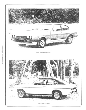 5
5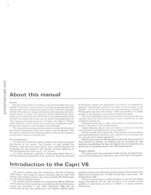 6
6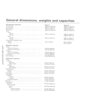 7
7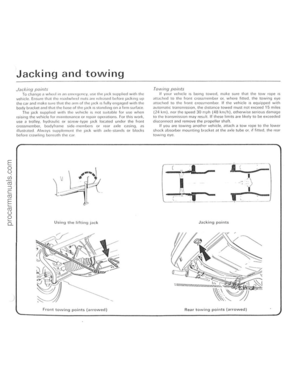 8
8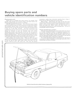 9
9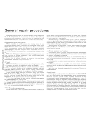 10
10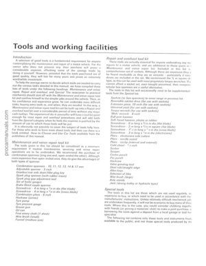 11
11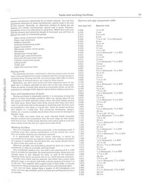 12
12 13
13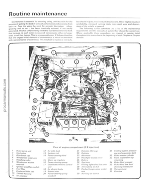 14
14 15
15 16
16 17
17 18
18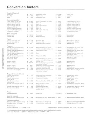 19
19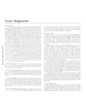 20
20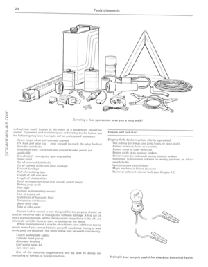 21
21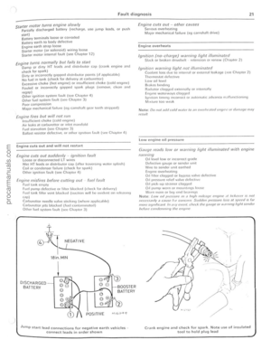 22
22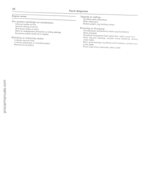 23
23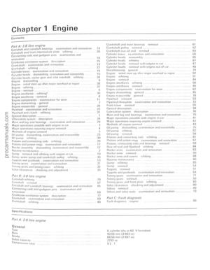 24
24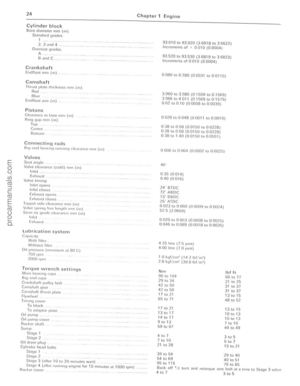 25
25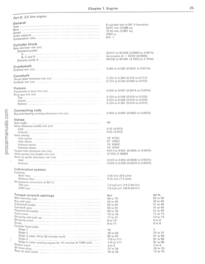 26
26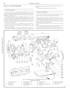 27
27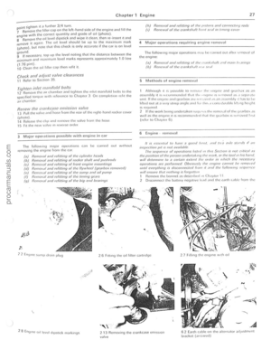 28
28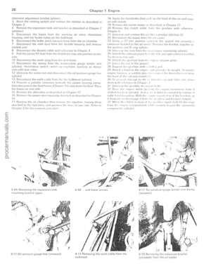 29
29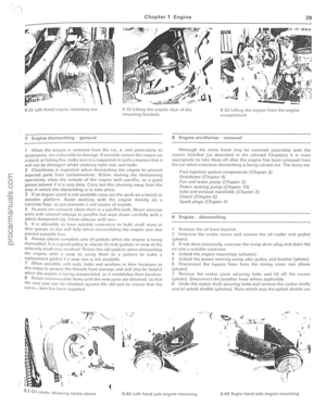 30
30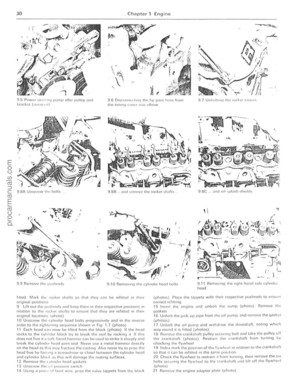 31
31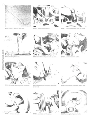 32
32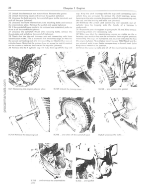 33
33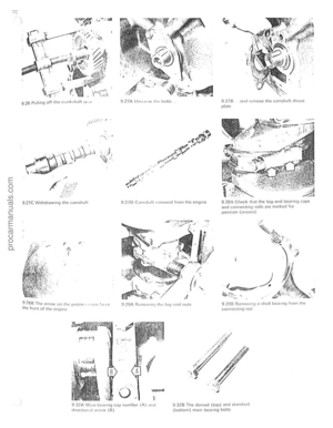 34
34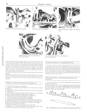 35
35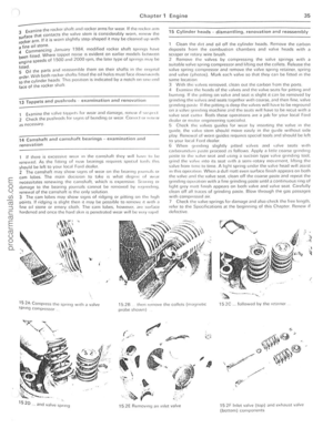 36
36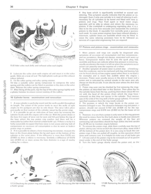 37
37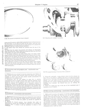 38
38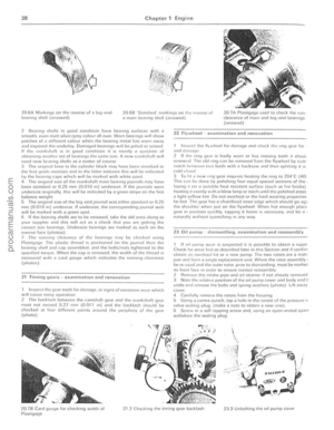 39
39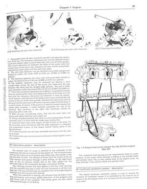 40
40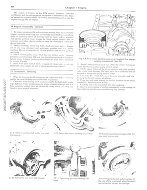 41
41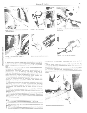 42
42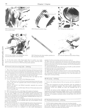 43
43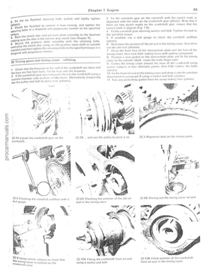 44
44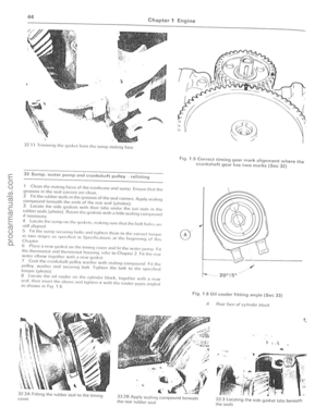 45
45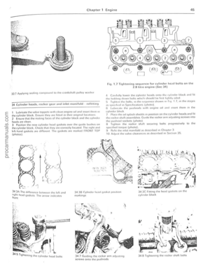 46
46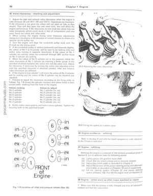 47
47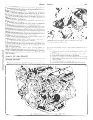 48
48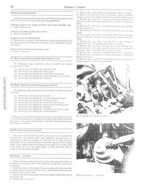 49
49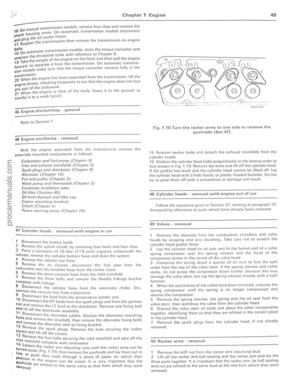 50
50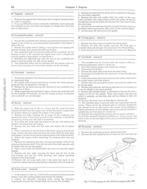 51
51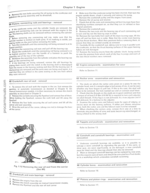 52
52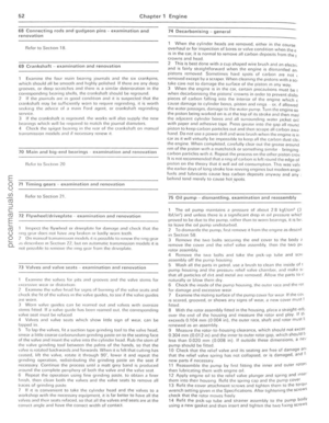 53
53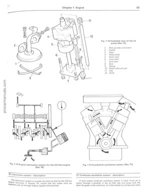 54
54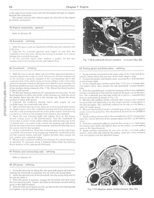 55
55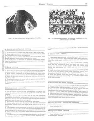 56
56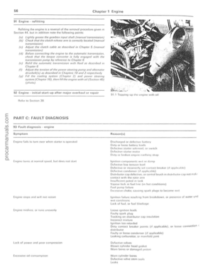 57
57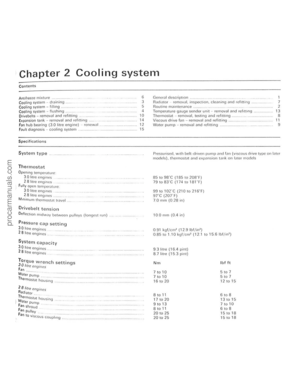 58
58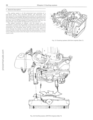 59
59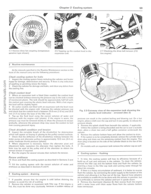 60
60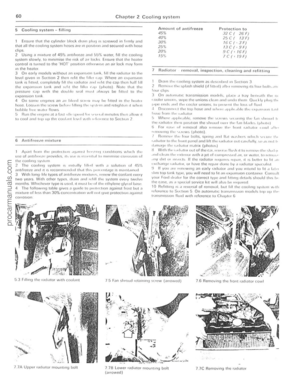 61
61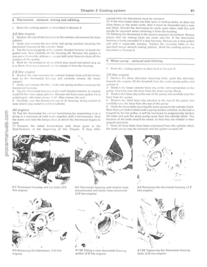 62
62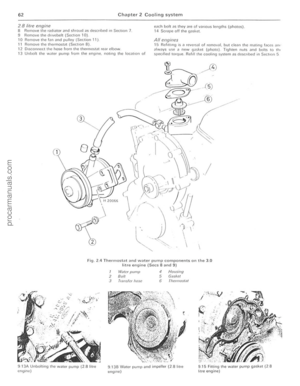 63
63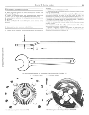 64
64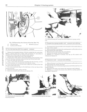 65
65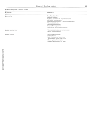 66
66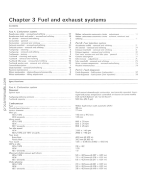 67
67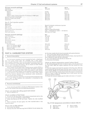 68
68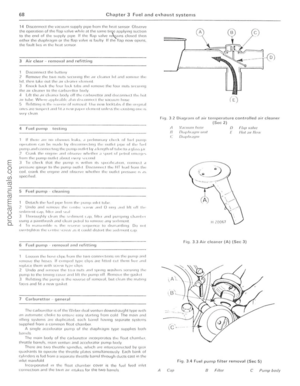 69
69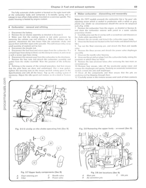 70
70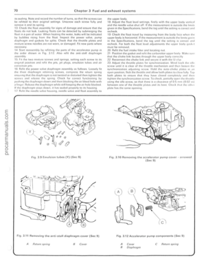 71
71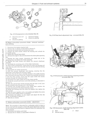 72
72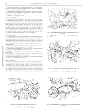 73
73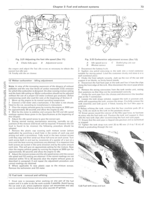 74
74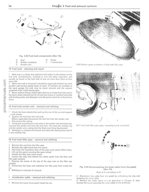 75
75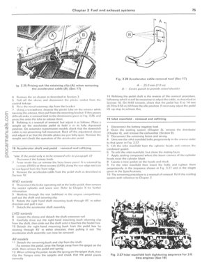 76
76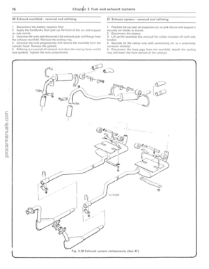 77
77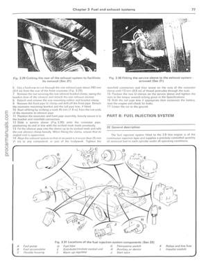 78
78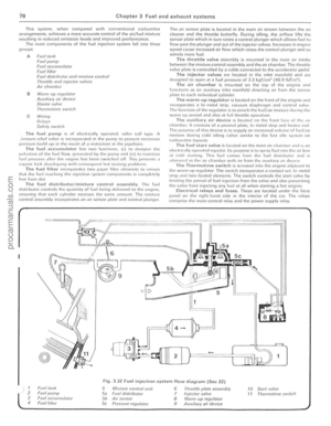 79
79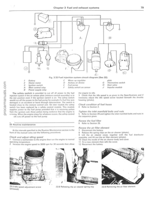 80
80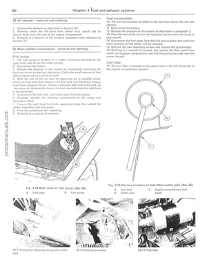 81
81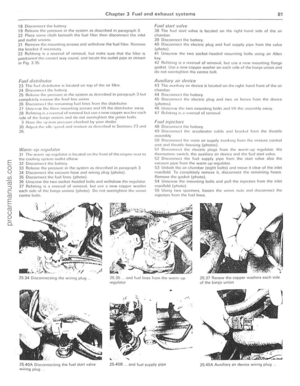 82
82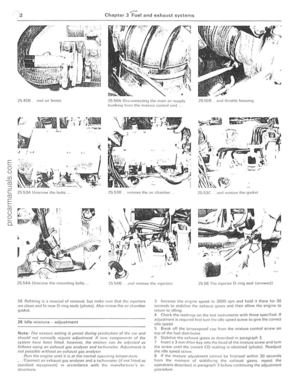 83
83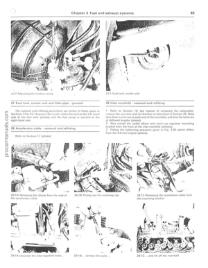 84
84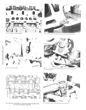 85
85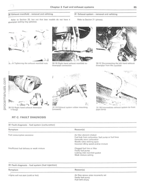 86
86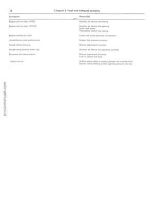 87
87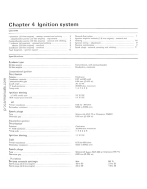 88
88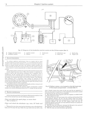 89
89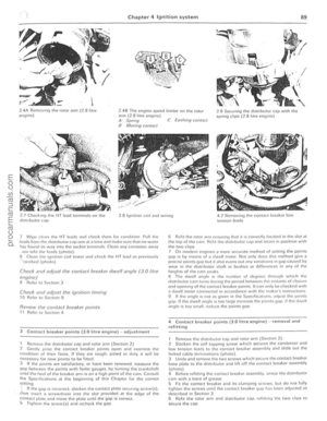 90
90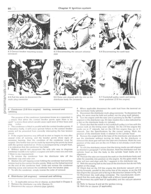 91
91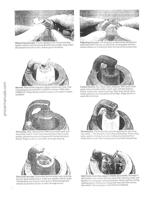 92
92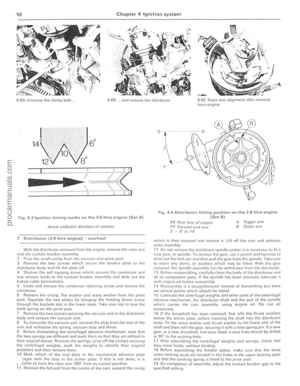 93
93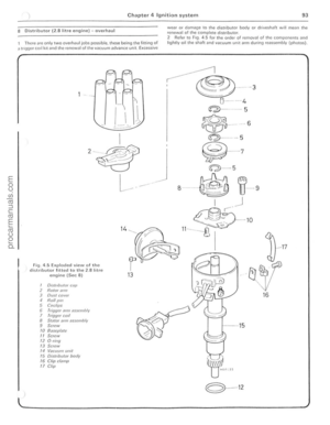 94
94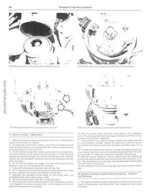 95
95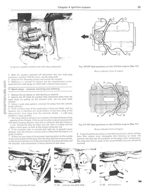 96
96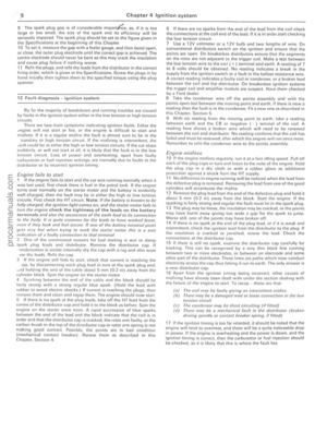 97
97 98
98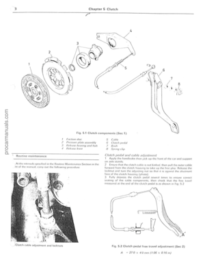 99
99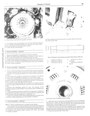 100
100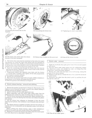 101
101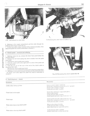 102
102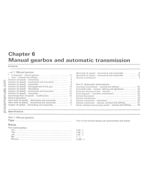 103
103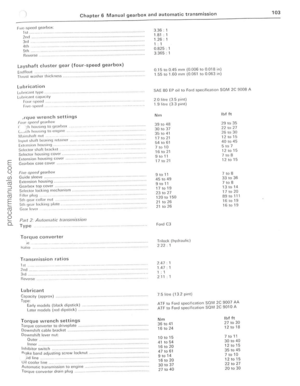 104
104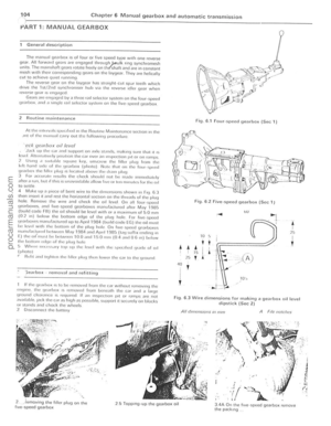 105
105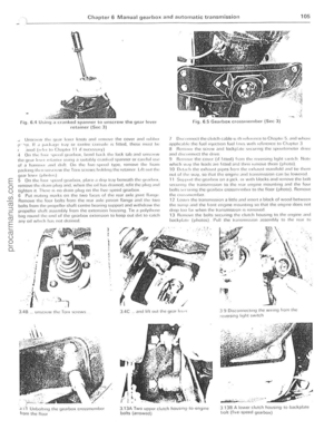 106
106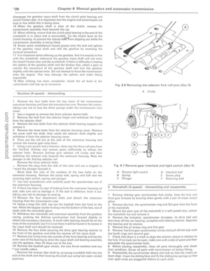 107
107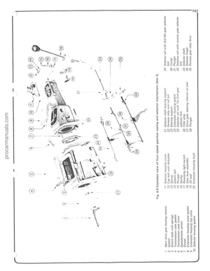 108
108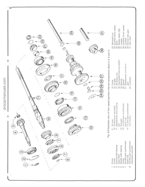 109
109 110
110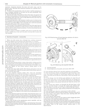 111
111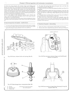 112
112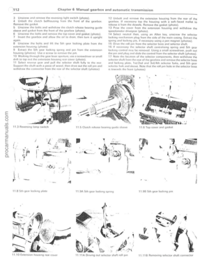 113
113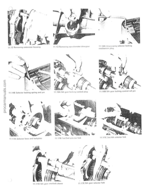 114
114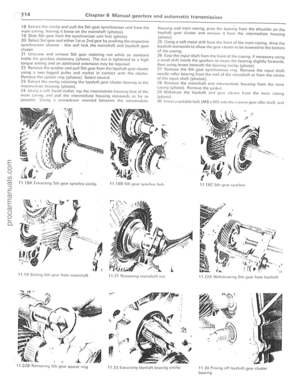 115
115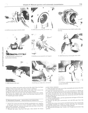 116
116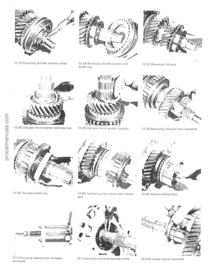 117
117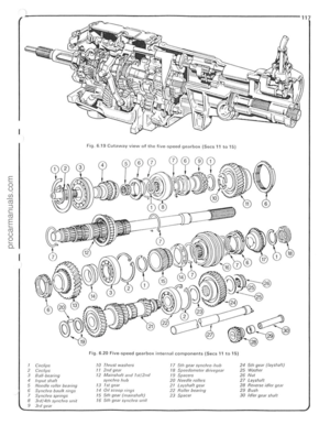 118
118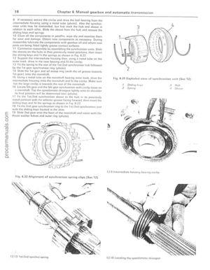 119
119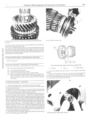 120
120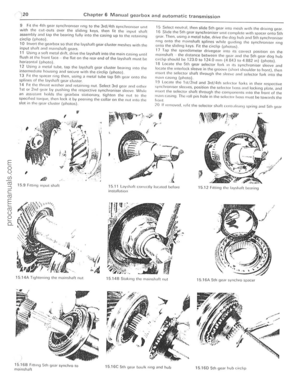 121
121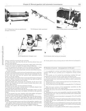 122
122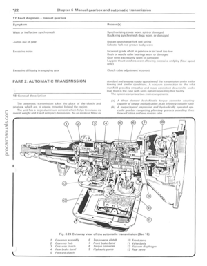 123
123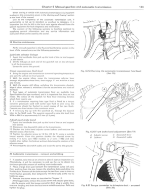 124
124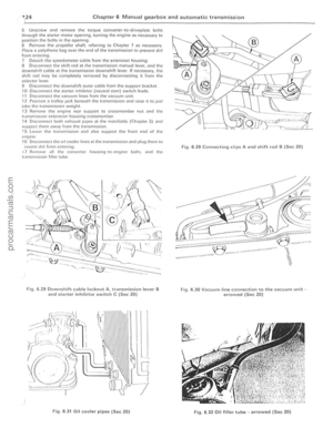 125
125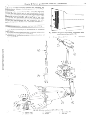 126
126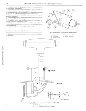 127
127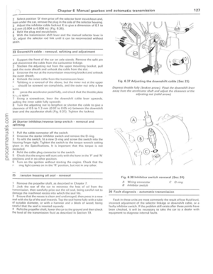 128
128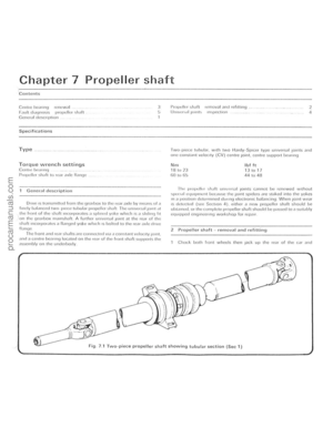 129
129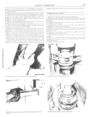 130
130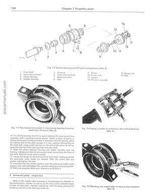 131
131 132
132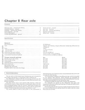 133
133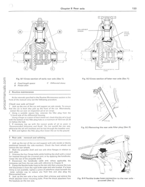 134
134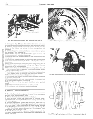 135
135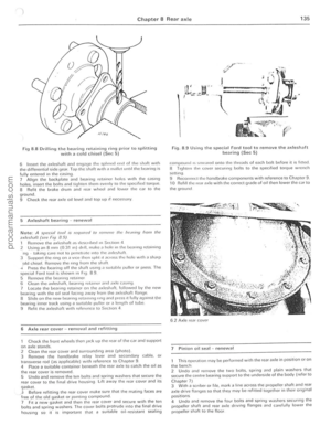 136
136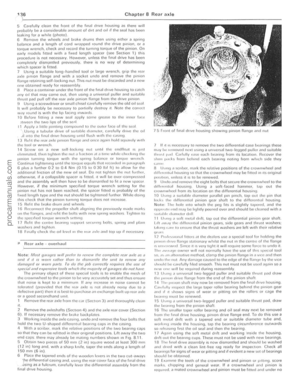 137
137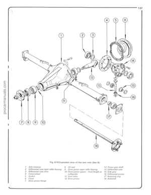 138
138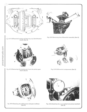 139
139 140
140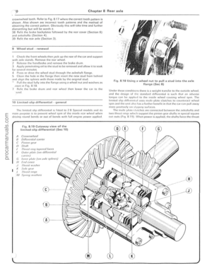 141
141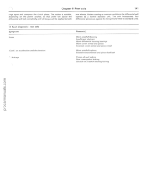 142
142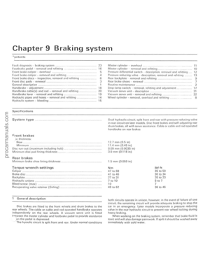 143
143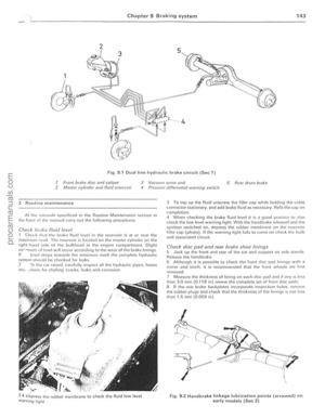 144
144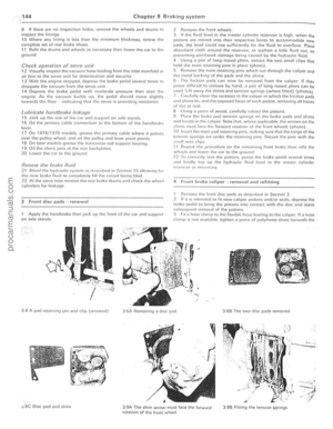 145
145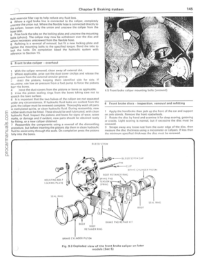 146
146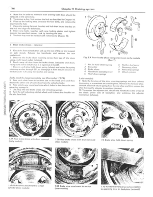 147
147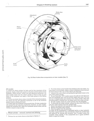 148
148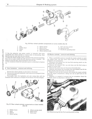 149
149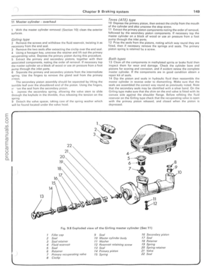 150
150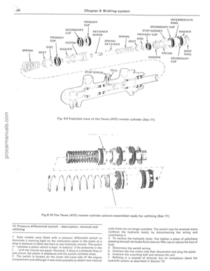 151
151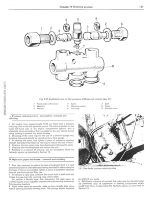 152
152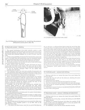 153
153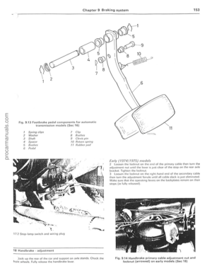 154
154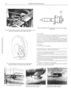 155
155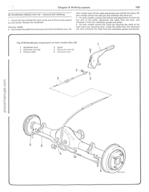 156
156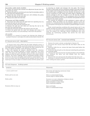 157
157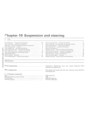 158
158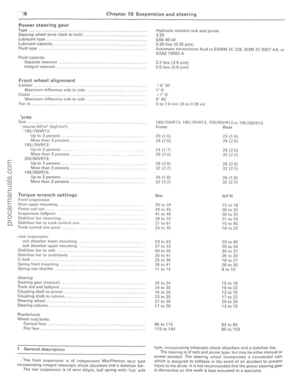 159
159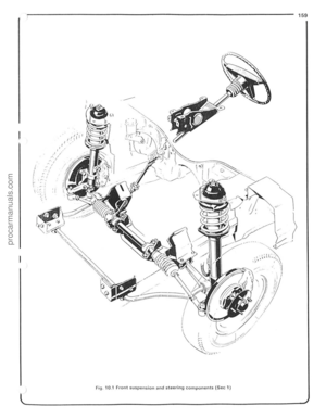 160
160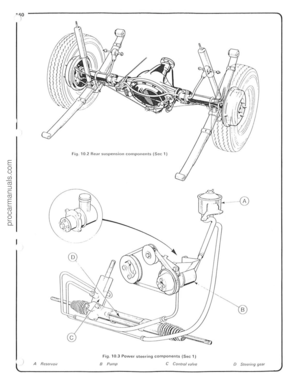 161
161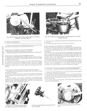 162
162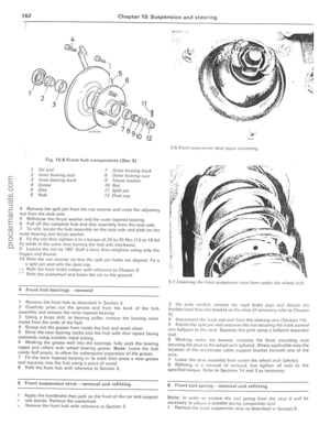 163
163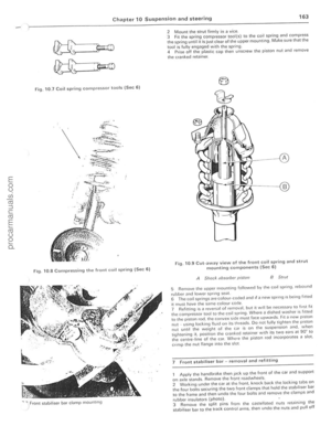 164
164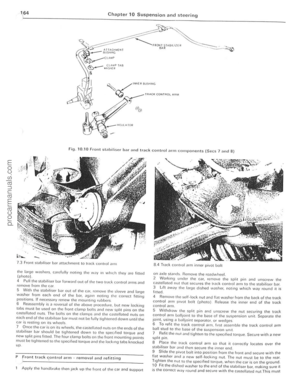 165
165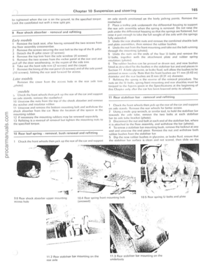 166
166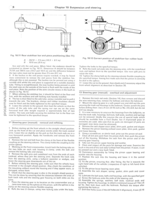 167
167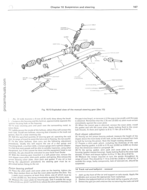 168
168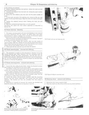 169
169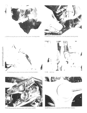 170
170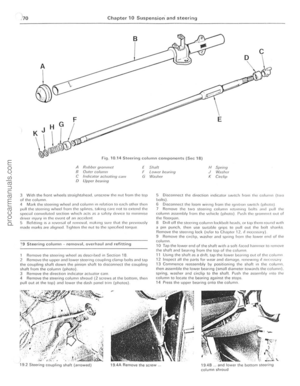 171
171 172
172 173
173 174
174 175
175 176
176 177
177 178
178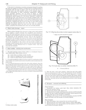 179
179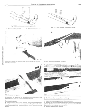 180
180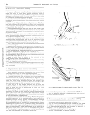 181
181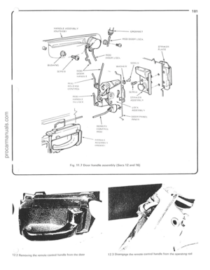 182
182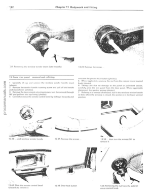 183
183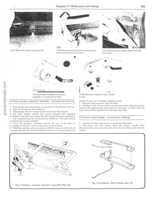 184
184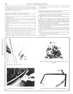 185
185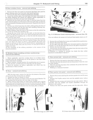 186
186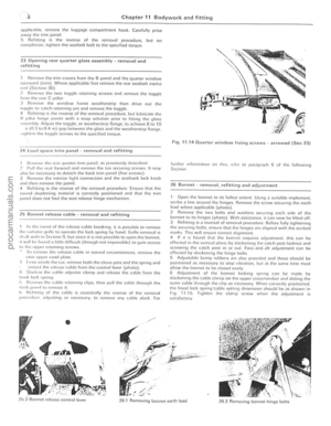 187
187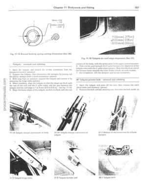 188
188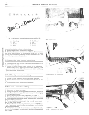 189
189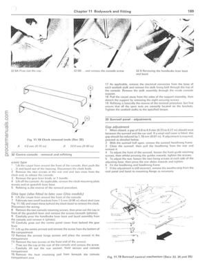 190
190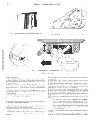 191
191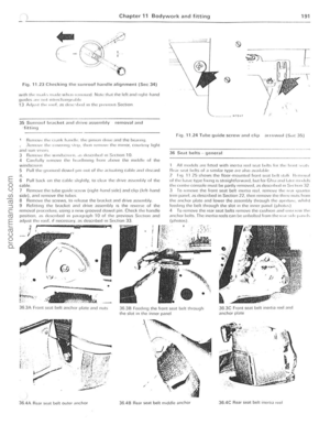 192
192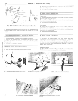 193
193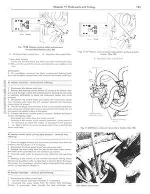 194
194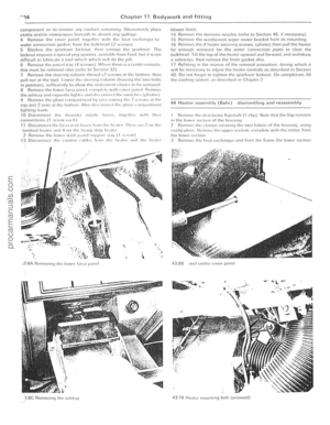 195
195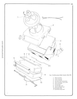 196
196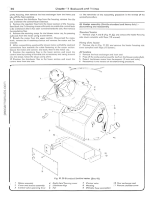 197
197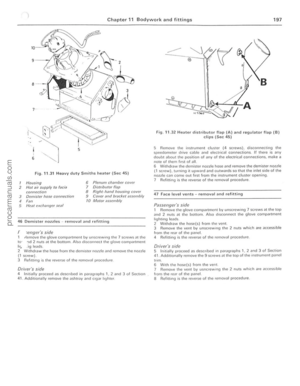 198
198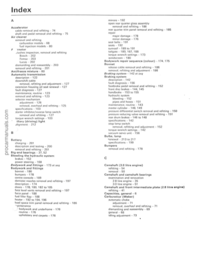 199
199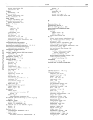 200
200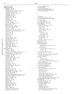 201
201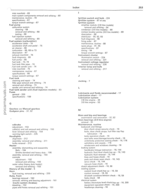 202
202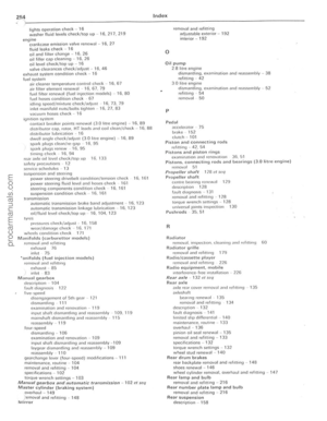 203
203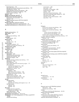 204
204 -overhaul
There arc only two overh\"ul jol)s possible. these being the fitling of a t\"UUcr carl krtllnd the renewal of the vacuum adva")