Page 105 of 205

PART 1, MANUAL GEARBOX
Gener\"l description
The nl<ll1u,,1 \je<lllJo x IS 01 lour or live speed type with one reve rse gear. All fOlwiud")
104 Chapter 6 Manual g earbox and autom ati c transmission )
PART 1, MANUAL GEARBOX
Gener"l description
The nl
The reverse Ilear all the l.1ynenr has St,nluht·cut sp'" teeth which dllve Ihe 1 st/2"d synchrOlliser huh via the reverse Idler IJeM when I(~velse geiu IS (J1l\Jilge
Ge;u$ "re ell!J
2 ROlltine Illainten,lIlce
At the "It,,"v
"cc k Yf.'ilfbux oillevul
J.1ck up th,! C;lr amI SUPpO'{ on a xle s!;lIlds. m;lklll\j sure lh"lll 'S levI,1 Alt""l.ltlvely PO~III()n Ihe Cill over .111 "lsfH:r.IIUIl I"l 01 on lamps
) US"'~J ,I s\III, II,le SqLl,lIU key. un~r:",w IllI< hiler pili" f'O'l1 Ilw Idt h;1I1d ~I(h, of Ih(, oe"rI)Ox (pholo) Not" Ihm Oil Ihc lo"r-sp<:ed 11".101)0 the hll", ph,O IS 101:
4 Make UP" piece of bent w ire to Ihe d"llells'ons shown III r-'!I G] lhen IIlSCll II ,II1d ,eSl Ihe ho.ilOntal seetlO'l 011 Ihe tllIca(is of the pIli\! hole. Remove the wire and check Ih e all level On all lour-speed
\Jearhoxes . ,11l(1 f,ve·speed ge.1rhoxes m.1nufactlltud ,,(w, M"y 191;1S (!wlld code FIl) the 011 should be level with (]I a milx"num of 5 0 111111 (02 Ill) helow Ihe iJottOIll edne of the ph)~J hole. I: or ('ve-speed !1(;"'IJ()XI!~ m;lIlufactured liP t o Ap,,1 1984 (Iwlld co(ie EG) Ihe 011 "'list I,,, I"v'" W ill, 11,,; bOllom of Ihe plUH hoi" On I,ve· speed Ilca,hox cs "h"nda<:tu,,,,II,(,twe,)Il M"y 198<1 ,IIld 1\.11111 1985 (Iall sulf,x (,n(iIlHI II'
E) the o'("ltI~1 h" ""'w""" 1 0 0 ""d 150 """ (0 <1 alld 0 G 'n) 1,,;low 110" I)()UDl Il "d~I'! of Ihe I'lu~1 hoi,!
G WI",,,! "'";"s~.,,y top "I' l h " lev,,! with II", ~1'(!<:I(oed !jI;I(),., 0 1 001 (phulo)
" n,,(ot and "!Ih,,,n Ihn fill", plu!) Ihen lowe, Ihe "II to lloe ~)lolllHf
-;;e.1l'lJox -rmll()val ancl .efiuinu
If the IJ"ilrl,ox IS to he 'emov"d from Ih e Cill wllhcHJI romovlIIU Ihe ""II"l(J, Ih" !1'''"j,UX IS rumov,!d Irom heneallo lloe car Jnd il (,IIUe wound cle.11le. support It securely on hlocks 0' stands ,1nll chock the wheels 2 O'SCOIU10Ct the ha tlery
Fig. 6,1 four-spoed \Joarhox (Sec 1)
Fi\J. 6,2 Five-speed !Jcarhox (Sec 1)
I.e , ..
-~
t 25 W II I !
t A • I I I 15 I
7 (11) no I I ~
~-
" I /
~ 10\,
· ... 1--=" ...
Fig. 6 .3 Wire dimensions for IlHlking a geilrhox oil level dipstick (Sec 2)
All dUllet/SIOIIS J/l IIUn A File lIole/n's
:; .
.. ~ .. -,.' . • <
! ,,;
'r '
,j/
' I
live-speed 25 TopP lng'up the gearbox oil 3 ,4 A On the lIve -spee d UOilfhox remove the pack,n g
procarmanuals.com
Page 106 of 205
 Chnpter 6 Manual gearbox ililel <llltollltltic trnosmission 105
-
Fin. 6.<1 Usi\",! a cranked spalliler to unscrew the goar Inver retainer (Sec 3)
Uus;\",,,, 111\" !I\";) \"1 knOiJ and \",lllOv,")
) Chnpter 6 Manual gearbox ililel
'-
Fin. 6.<1 Usi",! a cranked spalliler to unscrew the goar Inver retainer (Sec 3)
Uus';",,,, 111" !I";)' '"'1''' knOiJ and ",lllOv,! 1he COVlJt ly !:';lIlkud spanner 01 ca",Iloi II~" 01 aha"""", .",,1 dill! On llw j,vC 'SI",,,d (ype. remove tl", 10;"" P
oil wl"d, Ira" not d'ni"ed,
Fig. 6_5 Gearhox erossltH!lllhcr {Sc. ; 3)
'I 0,,,(I)I)I
:C1 the cl,,[r,h c011 st:ClII"'!i lire tr,"'Stl1l~5'()1l to (he "';11 "1\~J'IlC mourI(tll\! ox C'OSSIl\('mIH" to lhc floo, (photo). Remove Il,c C'''''',IIII:rniJcr 1 2 l.mV<'1 [he (,nnSIlHss'on a lillie ,Ind II\S(:r[" block 01 wood hctwecll lhe SW"I' ;Ind the II()nt ellUHw mOI" lll\J so lhm 1hc cllOllle rioes not d,op too I;" when Ihu 1r,IIlSIllISSlon IS '~I))()ved 13 [l"mI)V" 1hc bolts secu"l1g the clutch hOIlSlIl!! 10 [Ile en~l'l\e ;)l1d
hn ekpl.,,!! (photos) Pull the ['.lI1SIlHS",OIl ;,sselllhly I() Ihn 'c;" 10
.,..
3.4C
[ho) gc"d)ox e,ossmumhe.
).,
{" ; ",
3.13A Two upp.:. cllllCh houSIIlU-lO·engrne boilS (arrowed)
3 13B A lowe, clutch houslflg-lo·hackpl"te I)olt (I,ve'speed (JeJrbox)
procarmanuals.com
Page 107 of 205

·06 Chapter 6 Manual gearbox and automatic transmiss io n
disengilge the gearbox inpu t Shill! hom ,ho clutch p,Iot bearing ,111(1 clu tc h friction disc. I, is imporlanllhal,hc engine and transmi ssion <'lre kept in lino while this is being done. 14 When the gearbox shaft is cleDr of the clutch, remove th e
tran smissio n assembly from bCn(!illh the car.
15 When refiuing, ensure 1il1 the clut ch pilot h earing in the end althe tfilnksha h is ill plilce Jncl is scrviceDble. Tic the clutch lever 10 the clutch housing, 1 0 pr(!venllhe release le.rertrolll slipping out while the ,Wnsmission assembly is being lined. 16 Smear some molybdenum-based grease OntO the end and splines 0' the gearbox input s!mh lind refit the gearbox by reversing the fcmovili p.ocedure. 17 II is impO.IMll when offering up the {jOMOO)(. th,lt il is e~
th e clutch ffiction drsc i1nd the Cfankshnft. Ifthe.e.s d.iilcul1y Inlnatinn th e splrnes 01 the gea.box shillt ,1no the frrctio n oisc. select iI \)em to 'CSlrain the movemcnt of the gc,lrbox shillt nnd turn the gearbox
slightly until the splines enter Do not iluempltO lo.ce the tfilllsmisslOn
ontO thO enlJlnO ThiS Illay (i
ImpOSSible
'8 Ahe •• el,uinn has been completed. chuck the 011 level Ifl t he .r
Gearbox (4 'S II001l) -dismantling
Romoye the lou. bolts hom the 1011 cove. 01 the t.ansm.sslon c~t()"sion housin!J ilnd f.om the lri"'snHs~ir)Ol eo'S<' Ilcmovflthc \:oye. s.
t.1king c
from th e seloclOl shalt. 4 Remove tho twO bolts from the selectol sh
5 Remove the Ih.ee bolts from the selector hOUSing COVCI. Remove the cove. with the shaft. then ro tate the selec tor sh
th c 15t/2nd. 3!d/top and .cve.se oe,1'5 suiliClently to rele
plullger ill th o 3.d/top selecto. '<1'1. Remoy e Iho th.ee selecto. lorks. J Remoye the plug hom the side 01 the c
rca •. Allow tho laygeal cluste. to drop into the ho ltom 01 the box. out 0 1 mesh wilh tho lIl<1inshalt gea.s. 15 Withd.aw the mainshalt and elflension assembly from the ge
tho '.ont 01 the gembox and slide the retainel 011 the input shalt. 17 Remov e the circlip hom the outside 0 1 the fronl bearing and tap the outer raco of the bearing to d.ive the inpu t shillt and bea.ing assembly into the gea rbox. then lilt them out olthe box . 18 Remoye Ihe laysha lt geaf cluste •. Ihe two th.ust washe.s and any I"'o se needle 'OIiOfS.
R emoYo the .eyerse idle , shah by sc.ewing a suitable bolt into Ihe end of Iho shah and then leye.ing the Sh;'lit Out uSing Iw o open ·ended spanne.s. Fi\)
.
6.6 Removing the seleclor 10lk rolillins (Sec 4)
A CIfC/'11
Fin. 6 .7 Revorso gear interlock nnd light swil c h (Sec 11)
A Ravelse liyh, switch 8 Swing C Plf/ngcr
o h!/ellocl< ball E Sc,ew IJlug
Rct.1ininy bolt F
5 M
Remoye 3rd/top gear s yn chron ise. hub ci.clip Ense the hub amf
thud gear lotwald lly lel/erinu the,n gently wrth a p
th e mainshah nUl and lemoye it 4 R emove the loc kpli/te . speedometer dfivegem. ilS d.ive ball and Ihen level 011 the reaf bea.ing. complcte With bearing IClaine •. Separate the bea.ing and its lelainel. 5 Remove the 011 scoop ring and lils i gear . 6 Removo 1 sl/2nd gear synchronisc. ci.clip and pull 011 the hub with the bi/ulk .ings and second gear. 7 Check thallhere is a mark to align the selec to. sleeve in .elation to the hub. II no malk can be seen. make one with a dab of paint ~nd then dismantle the synch.oniser hubs. 8 8010/0 sta.ting .eassembly. Clean all parts thoroughly 3nd check
their condition. Smear all Pi/ItS wilh tr3nsmission 011 befo.e fitting .
9 Reassemble the synchroniser sleeve and hub so that the nlafks on thorn align . Inse.t the sliding keys and 1IIIhe shdrn\) key sp"ngs so Ihat Ihei. open ends afe stagge.ed re lat ive 10 each other
procarmanuals.com
Page 108 of 205

~
~ ,
~"i
~' .2
, Mil'" dfivc gear bearing fewincr 2 Gasket 3 Detent balls with springs 4 Transmission case gasket 5 Tfimsmission case cover 6 Speedometer pinion 7 Dowel 8 Extension housing cove! gasket 9 Ex/ension housing lOP cover 10 Selector housing gasket
0) ® (6 o I , ,
, i
"' t:< '
I , - \.f' -
(t!
,Wi 1m '~f" .'-../ '---" .... ......-t ' , ..
-----~:.---~
@@y314 , /
'" '". I-@
< i~@ -. .-.J.'
"...J\7' "'-', " . -,-;. , '\. .. ' --..,
~ .o.--? 0, .' '-;, ;:-~ \"'~. , . \~ .;; (3/--.,.~ ~1'\ . "~., . -,~" "~\_. \. ... " . , ~,
'i::
'r'" ~
F ·® (" ,J
J
I
- @
' \... . --; , >. ..~ . ./ j\,
' r<»., ~\ "":~" < ,
"
.. ..J ~, ' ...... .' ;". .~ . .-... ' ";:,;... '( , . -~ '23' " . I _./ _~,~ '.' _ .... JIi'"'"' •. ~ _",_ . ' ./.' 25' _ ..
; .. ' " .~'W
--<. .,y 'B Y ~ • --, 1 ":-'..., '~~ ,
<-.~ ~
ff,v ~30 ~ '.~, 32
@ < ,
. >
--®
1.20,
21 . ,
\< /22 , .
~" ; " "-,'
----@l . ' .
@
Fig. 6.8 Exploded view of four-speed gearbox casing and selector mechanism (Sec 4)
'I Selector housing cover 21 Selector shaft bearing support 29 Seleclor rail wilh 3,d/4th gear selec/or 12 Cap boll wllh lockplale 22 Reverse relay aIm foil pm fork
13 Spring 23 Bcaring sUPPOfl 30 Circlip
14 Delenl ball 24 Extension hOUSing gaSket 31 Plunger
15 Plunge! 25 Se/ecto! fail wllh 1st/2nd gear 32 SelCClor rail with reverse gear selec/or
16 Sprmg selector lork fork 17 Reversing light switch 26 Fiffer plug 33 Selector shaf( 18 Gear {ever assembly 27 Drive gear, bearing relainer 011 seal 34 Selector finger
19
Oil seal 28 Plunger 35 Reverse gear relay lever
20 E~tension housing bush
~'c:-.:cc::-:-.:c.:,.,· .. , . .... ,
~
~ 0 ~
灲潣慲浡湵慬献捯m
Page 109 of 205
<
®
lt~
--
fC ,
~
~r
-
>
-
/
~~~ ~ ~ 1
~~6® ~\~ I
.. ~ '
®0 < ®h ~ , @
v-\)):J @
j •
~ @
@
-
j
@
j
@
,
,
>
.7'\(:;;7 j
'<;:) ':l
;;>
11:;>-
~
@ ®
Fig . 6.9 Exploded view of four-speed gearbox internal components (Sees 4. 5. 6 and 7)
1 CIfCltp 2 Cllcflp 3 Grooved ball-bearing 4 Input sh
9 3rd !
23 Mainsha/r nul 24 Laysh;1fr /hrust washer 25 Shim 26 Needle folfers (22) 27 Laygear 28 Layshafr (hrus/ wilsher 29 LayshJI( 30 Reverse ,dler gear 31 Idlcr shall
~
'"
procarmanuals.com
Page 110 of 205

10 lI:IClllhl} syllchlonl~!\"!! t,,1nlk \"n[J onlO Ihe COl It! 01 second !Je")
Chapter 6 M anual gearbo x and autom atic transmission 109
Fig. 6.10 Rcvcrsu [JC>lrill[J '"cill[J fo rwMd s (Scc 5)
10 l'I:IClllhl} syllchlonl~!"!! t,,1nlk "n[J onlO Ihe COl It! 01 second !Je,'. ,1n(1 511110 11 onl0 I he Ill:H(\sili,l t tOIJlHiler wltil h t/2nd lIe,,, wnclHOlliStH iluh. Thn \In", on Ilw huh should Iilcn 100war d. 11 Fit Ihe sync hronise, lJ;oulk WI(I >llld the c"clop ""Iudl holds th n
sV"ch'Olllser hub in ,)I;lCC 12 Slide on hisl Ulli". so th>ltthe sync hronise. conI.' pO"'Oll 10,,5 ins ide the synch'Onlsing .i"U which ha s lust ~en f'IlC(1. 13 Fit thc oil scoop. wilh the all [JIOOVC lilCinU .e;lfwa.ds. 14 Apply !11ulii-pu'l)oSC [Jrf:ilse to thc billl·hciI.il1!J seilt 01 the ilc,,,,"U rctaine •. flellt the lelllinCf with the be>lll"g insCrtll(1 >llId Ihell slldll on lhe sr)acer. 15 Insetlthe d.ive hall 01 rh e speedo meler geM inl0 rhe sh"lt >lnd shue the spcedomete. wo.1lI ueM over i\. 1 6 1: ,1 I h e loc kpl>lte so thm the twO wbs ht II1tO rhe speedolllelC. wOlin \lCi" I(.'C'"SS Soew all t he not alld tl{.lhlen II to the to.que wICnch
SCllln!) !/,vun III the SI)()Clhcallotls. Ihen lock Ihe IIUt hy bendi"" th C
I"IJ w;osh!"!! 11 Fit lhu synchltJIu~r iJ,IlIlk 1II'!110 thll COliC 01 thUd !Jea. ;lIId lit them to Ihu 1,0'11 01 Ihu I"al,,~,h,,1t ,"It the 3.d/wp !W~. sYlldllOliiSC' huh.
With Its Wide ho~s IOWiUd~ Ihe le,u illid (illlil leWII) I( III pl;lce hy IIlllll!)
"'e t.:llchp
11I1)ut shaft (4·slleed) -dism 'Hlllillg and reasscmbly
It IS
not nccessa.y to (los",,,,lIlc Ihe Input sh
pOssible to ht the la'!Jc cllch" whldl .etillllS Ihc I/Ca.ing in 1)lilCe III the housinu. 5 Eilhe. SIJnd the UlpUt shalt up.iUhl on a bench and tilt> the be~.ing IntO plncc U5in!J a piece oltllhc 01 suiwble diMlete •. or usc the jilws 01 a vicc to SUllpO I! the be;uill\J ""d wp the rem ollhe i"flut shill! with a soft l.1ccd hammer. 6 When the b earing IS lully home. III tilC cllel'l) which .etains the bearing 011 the shall.
7 lilY!Joa r (4·speed) _ dis milnlling and reassembly
R e
move iI shim Irol11 cilc h end of t he layUMr. ,elllove 22 needle
rolle.s hom each enu of tha \JC
Wh",n alllh!;! rollers a.e III 1)lilCC. sm ear g.ease ovel thl;!m CO .etain them alld then sccule the sh un ave. Ihe ends ollho rolle.s Wllh y.ease . Due F
ig .
6.1 1 Position o f oil scoop ring with groove facing gcar (Sec 5)
Fi ". 6. 12lDyshDIt and !Je>lr cluste r (Sec 7)
10 Ihe h'!Jh levels of corque lfanSllulled th.ough the gealbo~ " IS ,mllo.tilnt Ih;)t all the needle rolle.s have exac lly Ihe s,1me dlamele. II Ihe n eed le .ollers ,n iI be,ulng have dlffe.ent (liamelc,s. thiS Will cause
t HIeve" IOile! dls urbu!ion which call .e sul t In prelll;)lu.e we
8 GCiI.box (4·speod) -e xamination and rcnovation
ThO.oughly cleall the inle"Or of the gearbox. and check lor d.oppcd needle . olle.s ilnd spr ing pins.
2 Ca.elully clean ilnd thcn e xamine all the component pa.ts fOf gene,al wea •. d,stOltion, slilckncss of f it . and damage to IlIac hi ned
I"ces and th.ead s. 3 E~alllllle the gea,s for e xccsslve wear and chipping of the teeth. Renew them as necessa.y .
beDr. II a small rodge can be felt at eilhe. end 01 Ihe shah il Will be necessa,y to renew it. R ene w the thrU St w ashe.s at eilch end. !i The four synchroniser baulk rings a.e bound to be badly worn and II is lalse economy no! 10 .enew thelll. New rings W ill Imp,ove tile
smOOlhness
7 Exam ine t he condilion o f the twO batl·beDring assemblies. ono on the Inpu l Shaft and one of Ihe mainsha Check Ihem for nOIsy
procarmanuals.com
Page 111 of 205
( an d automatic transm iss io n
operlltlon. looseness between the inner ;mel oulC. ;)ces. imd 10f genera wear. NOfIll.llly they should be .enewed on a gearbox lh<11 IS")
~10 Chap ter 6 Manual gearbo)( an d automatic transm iss io n
operlltlon. looseness between the inner ;mel oulC. ';)ces. imd 10f genera' wear. NOfIll.llly they should be .enewed on a gearbox lh<11 IS being .ebuil l. 8 II Clther 0' the synchrOnise. unllS ;nc WOUl II w Ill be ncccssmy 10 buy" complete assembly as the Pill ts ,lIC not sold individually. Also check the sliding keys 10' we;'!. 9 Examine tho ends 0' IhO scl(!C I(ll' lor ks where they rub "g.1In51 the channels in the peJiphery of the synchrOntSfl f units_If I)()Ss,ble cOIllp.."e the sclecw. lorks with new Units to hell) dC1Crminc the weill lh,,1 h,IS occtJUcd Renew thelll " worn. 10 If the bCilring bUSh ,n Ihe CXI(mSlon is b;uliy worn II,s OOS110 [
J Ge1Hbox (4·speed) -reassembly
When any hOlt screws "110 a throuUh hor". JOllll11\!J COlllpnulI/t Should hc nj)lllted to I he lhwads 011l11! holl helorc It ," InS/"h~1 2 Fit Ihe /cve.so Idle. He"r WIlli Ihc It,oolle on the !le;1I tuw;IId,. Ih,' lenr.lnsel! Ihe .dle, s h ah nnll dlllle 11111 with .1 pla~t.c·IIIl:IIIt].1 h;""""" unllllhc OOltOnl ollhe Slel) on the end ollhe shalt.s IIIIsh WIth lhl! ,,11.1 0 1 the gCJloox. Thc mIlled "
t he OIl lellHn horo 01 Ihe Ui ls k e l ,1nd tW:illnlJ IfJlilinur .lte ah\jl1fJd as III
FlU. 6 13 Apply 101ll1lng compoullll to the threilds 0 1 Ihe bolts. lIl~e
SpecIIIC(ltIOns .
0,1
the new IIlput sh,ll! ncedle rollel heilrlllg ilnd push I t 11)10 tllC oJorc 01 the input sha ft Slide the lOP gC(lr synchroniser baulk IInu on to the cone olthe IIlJ)u I sha h 8 FIt the extension houSll19 gnske!. lhen InSerl the ,1s~",hlcd mainsha/t into Ihe rca. 01 the box anll (frille II III untIl the nose 01 Ihe Illalnsh~h is fully engaucd in I he II1PUI shilh necdle l>c,l11nU 9 Carefully lu.n the ge;ubox upSIde down. so thilt the layshalt \}e,lr elusler dIOI)S mto engJgelllenl with the malnshillt Jnd IIlpIII shalt Check thilt the gear and the two lluust wilshe.s il.e III line and then c,l.elully push in the layshalt from thc leal. If necessary till) Ihe S h ,ll! In with the p lasuc·headed IHI/llmer. bllt take grC;lI CJre not to dlslodUe Ihe thruSI washels or needle .olle.s . When fully home. the h Ollom of Ihe slep on the .dlel shalt shOuld be In hnc with Ihe face 01 the box and Ihe mIlled flats should be in IIno wllh the Idler shalt oo.e. 10 Turn the geilrbo~ the lighl w;ly UI) Jnd align the hole in the 1>.111 bemll1g SUpj)Orl WIth the dowcl on Ihc cxtcnsion housing. Fit the eXlenSlon housing. Apply jOlllllnu coml)ound to the ttlle<1ds of Ihe bolts. InSClt them and tightcn 10 thO torQuc wrench seHlng gillen In the SpeCll l
C3tions . 11 1/ a new cxtension bush has been fllle(1. check Ih~t the notch 01 011 groolle III II ilhgns wllh lhe o ll,elurn grOOlle In thoJ extension housing. If thc now exlension housinU 011 senl hilS not illready been filled. slide It Ollel the extension Shill t and enrelully tap it in wilh n h~nllller and n
b lock 01 wood.
1 2 FIt J ncw O ·ring to the spcedomeler pll110n assembly. relit the ~Sembly and f it the C llcli l) to socure i1. ,3 Inser t the r(,lIerse gear interlock plungel. ball and spring. Fllihe boll with aloek plate and lIl$crl tI,c l.Iol t. TIghten the boll and bend Ihe lock plilles to seCure ,to
Fig. 6.1 3 Posilionin g of Iront hearin\} .e lainer oil return \}Ioove (Sec 9)
=-*.------t---.---- ---
FiU . 6.14 R olitting the Inyshaft (Sec 9 )
A hlSC//ing /,1vs/!I!f/ B ClJflec / lIi1:qlll!!efl/ of /,J)'$/I,III illld 'fJve.se IdlfJf sl!,lfl
1/1 Insert ~II Ihrce selecto, 10l~s Into Ihcn I)ositlons 111 lhe gearl)o~ 15 Shllc 1~1/2n(1 \le,1r selector ,,111 through Ihe r,ghl-hilll(1 bo.e mille
I:ilse. Ihell tluead ,t through the 1 S I/2nd gCM selector lo.k Align Ihe holes 111 tile lo.k and r~11 ,111(/ t<1l) in the 101l1)ln. Insert the plunUe/ into thc c,lse 16 FIt Ihe pltlllgc/ '1110 Iho 3rd /lOI) ge,ll selecto. lad. inscrt lhe 'illl
t h .ough Ihe ccnHe hore III the C,lse ;lnd Ihread the raIl Ihrough Ihe 3rd 101) gea. sel()(: tor lo.k. Fit the clfchp to Ihe groolle ;n the se lecta' lilll Ahon Ihe holcS III the selectol 100k and ,;lil. insert the loll pIn and lal) .t home. 17 PUSh lellerSC gc,'1 seleelo, r;llt Ih/ough Ihe lelt·hand bore in the hou$"'g. and then thread 11 through the rellerse gear seleclol fork. Align Ihe holes III Iho IOrk and 101.1. inserl a roll pin and tap it home. 18 FIt Ihe interlock plungC/< apply sealing compound to the plug and dfille In Ihe plug 19 Inse!! ICllerSe ueJI ,clay lever and secu/c it wilh a roll pin. 20 Inse't thO sCleCtOr shalt ItHough the selcctol housing COllel and fit the co~er using a new gaskel Insert the COlier rewining bolts and screw them in Iingel lIghl. 21 FII the sel/lCIO' sh:lh b'lIcket 22 Shdo lhe S(lIOClOr flnge. onto the selec tol shalt. Eng~gc the strew III the ,ece~~ in th O shaft ~nd tIghten the sc rew. 23 0101) lhe Ihloo dctent ba lls 1I1tO thcir bores in t he casc. g1Case the thleo sprinus alld Ilise rt thcm Into the recesses 01 tile yeJ.1>ox COllel. FII
a new COlier gasket and positIon Ihe COllcr onto II Insert the COllel holtS and tlghtcn Ihem to tho 10Ique wrench suiting (Jillen III lhO SpeClf,callons
procarmanuals.com
Page 112 of 205
 . lh,s d,mens,on shou ld be 0.9 mm (0.035 in).")
Chapter 6 Manual gearbox and automatic transmiss ion 111
24 Chec k the plilY between the selector finger and 3.d/top geM selC{;lOr .a,1 (F,O. 6 .1 6) . lh,s d,mens,on shou ld be 0.9 mm (0.035 in). lo m"ke t he chec k. move the selec to. leve. up to the .everse gea. SlOp. Us.ng a lever. push 3.d/top gear selector .all \0 the rear and then
measure th e clea .ance by rnsel1lng leeler gauges betwee n 3rd/top gear selector rild "nd seleClOr finger. If th e cleM,mce 's no t ns specified. it shou ld he conecled by chnnging lhe .everse interlock geM plunger for one whIch will give the ,'PI).opria te clearance. 25 F,t a new gasket 10 the e~lension housing cover. Posilion the
cove •. ,nSOI I the fi~ing bolts nnd lighten Ihem 10 Ihe torque wrench Solt1inlJ g,ven in the Specifications. 26 M,1kc su, e th atthe geMl>o~ dmin plug is I,tted and tigh tened where apphc, 1hlc. then I,ll the uenlbo~ 10 the COffect level with the specl l'ed
,,'
10 Gcnrchnnge lever (4,sjleccl ) - m odificnlions
1 To ,mp,ovelhe \]flnr ch nngc movemcntlJctwecn lh(: Hea.s. , smallm CO".,r levcl Sl)!"'g ,s 1'lIr,<:I. the new 51)/,nU d,amclr'!' bc inU 20 mill (008 aga,nst the orig,n;r l sp.,n!) IIiarllctm 01 2.5 nUll (0 .1 0 inl.
Fig. 6 .15 Cover. d ewnt balls and sprinus (Sec 9)
Fig. 6.1 7 Gearchange lever components (Se c 10)
A Spliny B Rct.1illiny pin C Pf;JSlic C ilP
Dlillcnsion X mUSI be gloater Ilran dimension Y
2 To renew Ihis sp.ing. lir sl remove the gear lever unit from the trnnsmission as given in Section 3. 3 Press or drive out the roll pin and remove the plastic cup (F ig . 6.17 ) ;rnd spring .
4 When reassembhng. check that the pin di('!meter is less thiln the width 01 th e slots (X ,n Fig. 6.17), II necessary grind down the pin and
d e·llUrr the slots by ca.e ful filing . When filled the pin slotS mus t face upwMds. 5 If the gear leve. was loose when in use. an O-ring can be filled in placo o f Ihe retainer sOill as shown in Fig. 6.1 8 .
6 When this flng ,s fmed an(I the gear leve. reIOCalr:!d. screw the retainer cap inlO pos,tlon so th ilt It jus t touches th e O·ring . Mark the relntlve pOSitions of tile cap
11 Goarbo~ (5·speod) -disillantling
1 Clean the e~tello. 01 Ihe gearbox w.th paraffin .,nd w.pe d.y. 2 Remove the clutch release beallng and allli lele",ng 10 Chapter 5.
0035;11 10.9 mill}
Fig. 6.16 Plav between selec to r finuer and 3rd/4th geM selector rail (Sec 9)
.. : . :,'. :", .
fLJ
··· ..
A
Fig. 6 .18 Cross· section of gear lever showing 0 ·rin9 (A) location (Sec 10)
i
i
procarmanuals.com
 1
1 2
2 3
3 4
4 5
5 6
6 7
7 8
8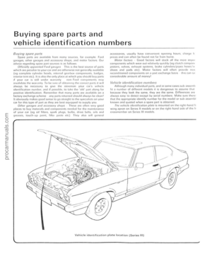 9
9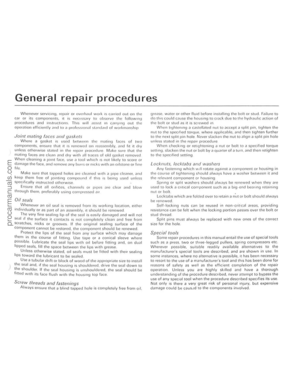 10
10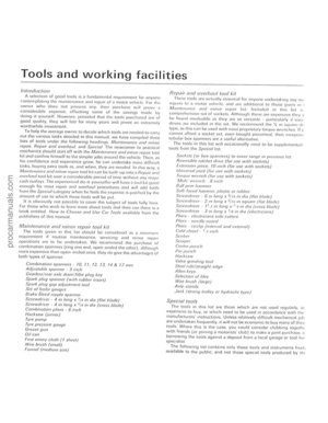 11
11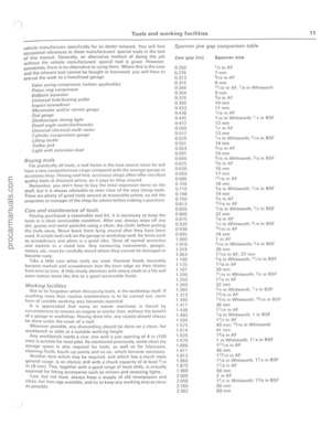 12
12 13
13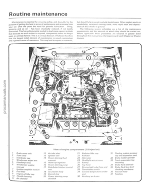 14
14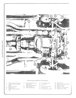 15
15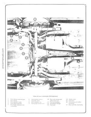 16
16 17
17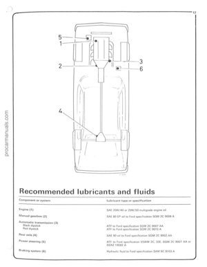 18
18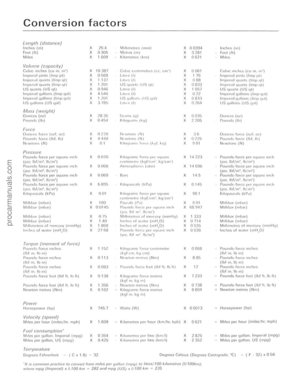 19
19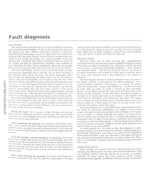 20
20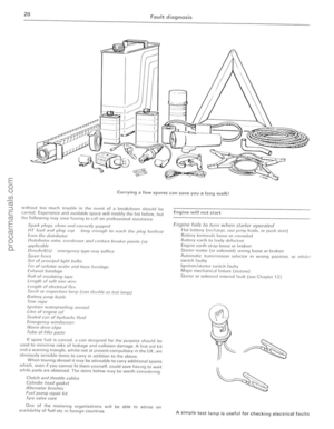 21
21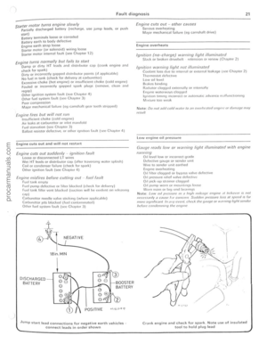 22
22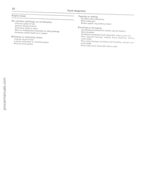 23
23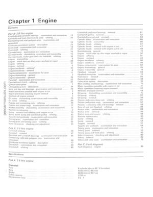 24
24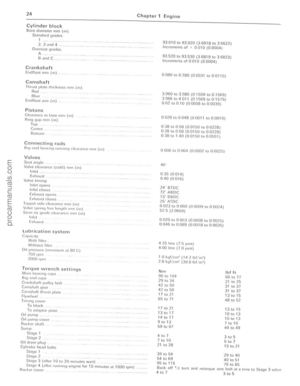 25
25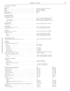 26
26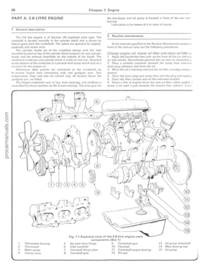 27
27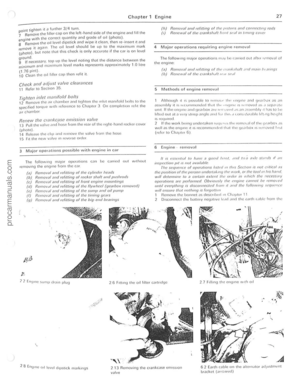 28
28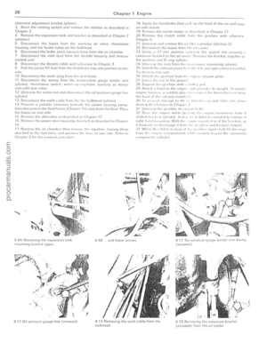 29
29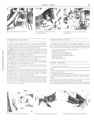 30
30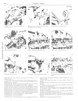 31
31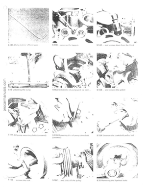 32
32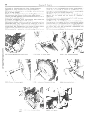 33
33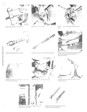 34
34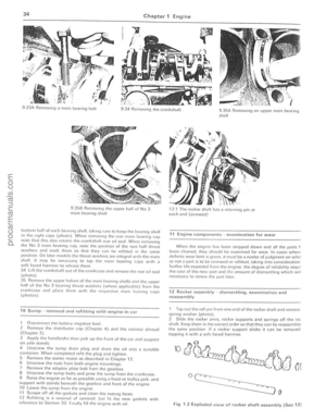 35
35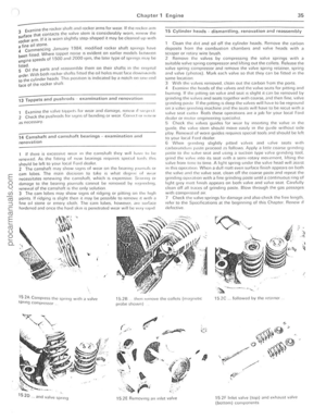 36
36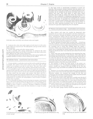 37
37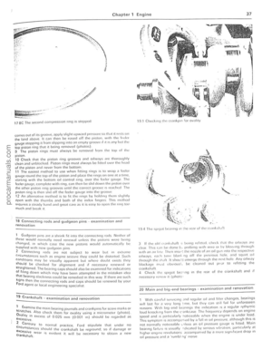 38
38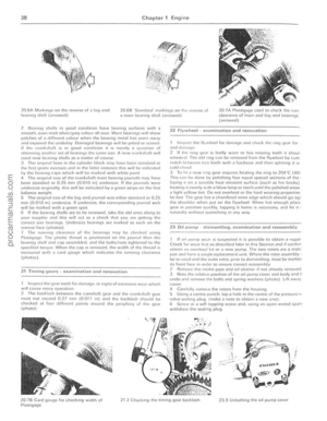 39
39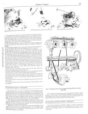 40
40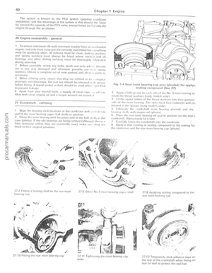 41
41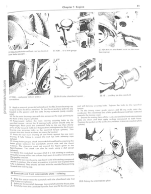 42
42 43
43 44
44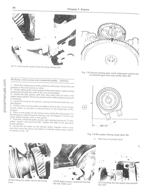 45
45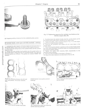 46
46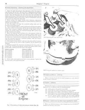 47
47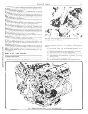 48
48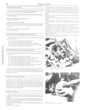 49
49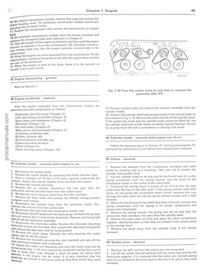 50
50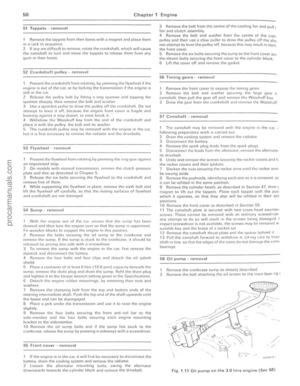 51
51 52
52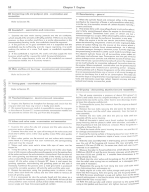 53
53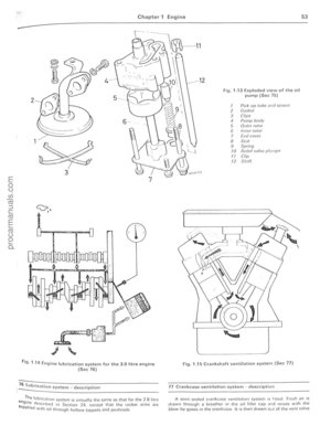 54
54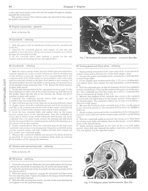 55
55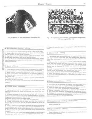 56
56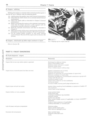 57
57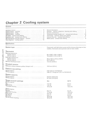 58
58 59
59 60
60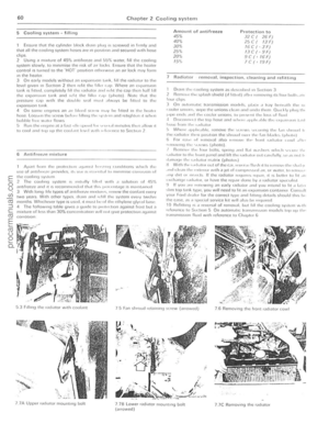 61
61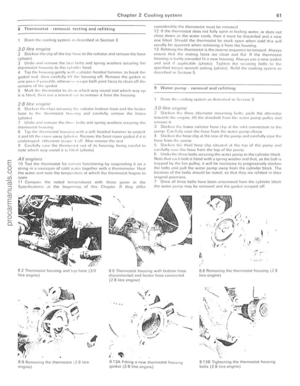 62
62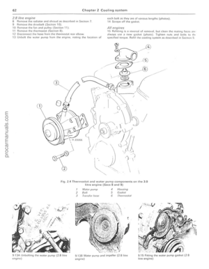 63
63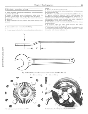 64
64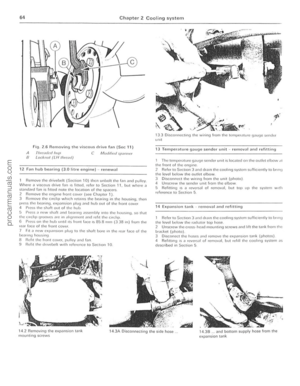 65
65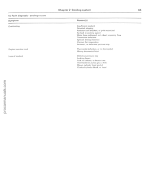 66
66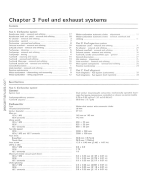 67
67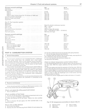 68
68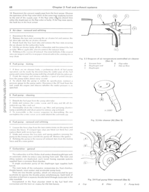 69
69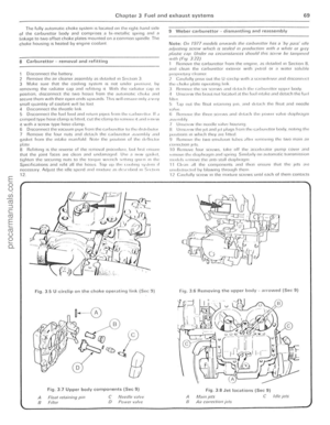 70
70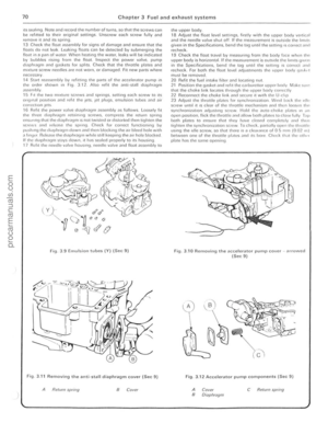 71
71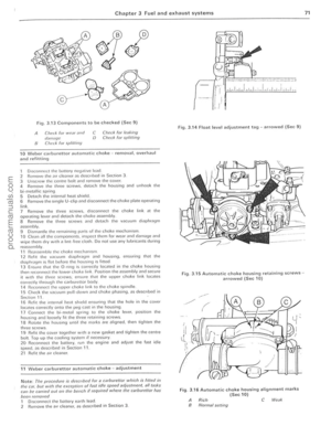 72
72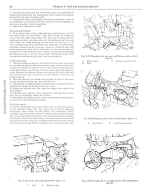 73
73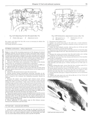 74
74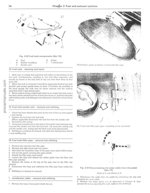 75
75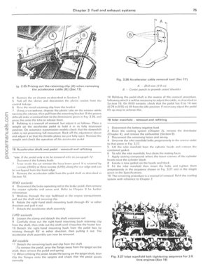 76
76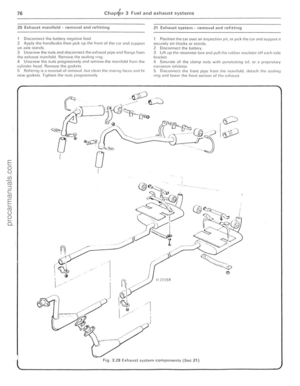 77
77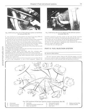 78
78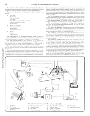 79
79 80
80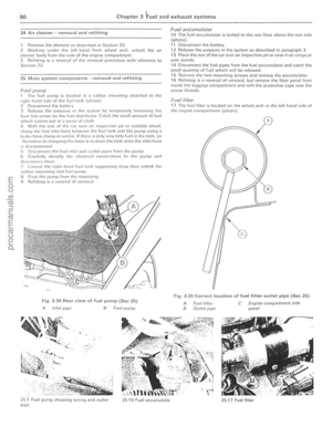 81
81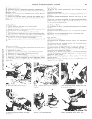 82
82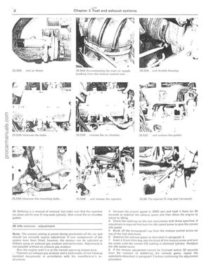 83
83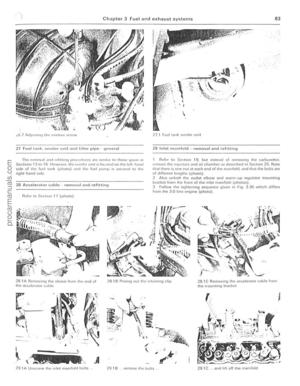 84
84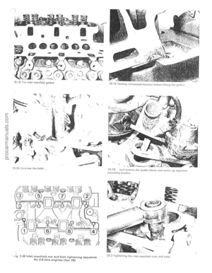 85
85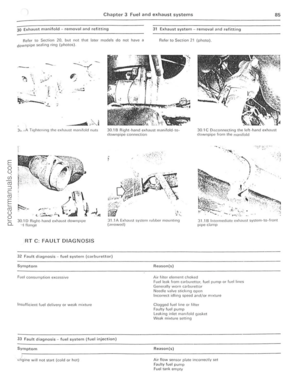 86
86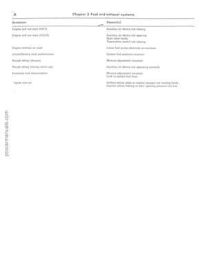 87
87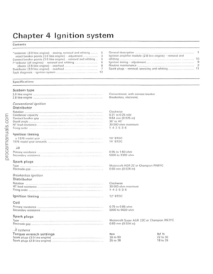 88
88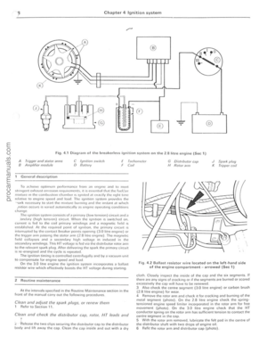 89
89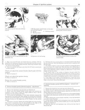 90
90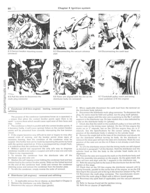 91
91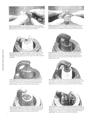 92
92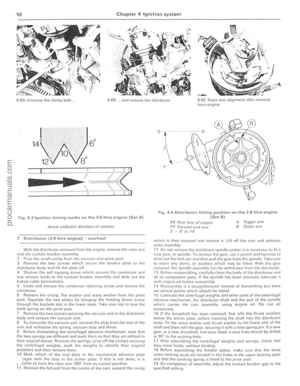 93
93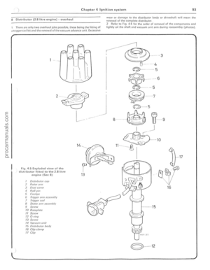 94
94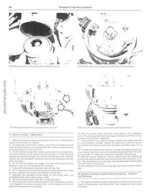 95
95 96
96 97
97 98
98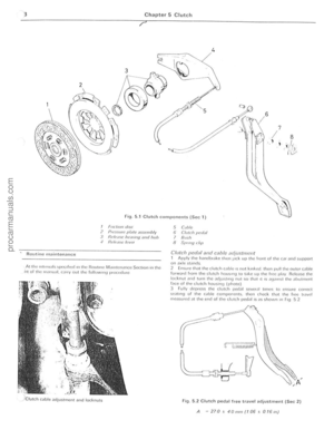 99
99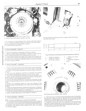 100
100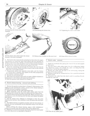 101
101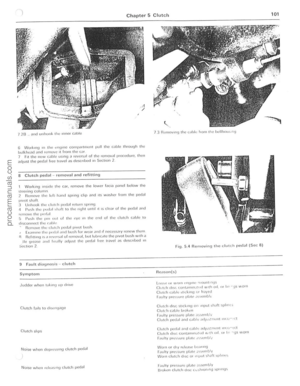 102
102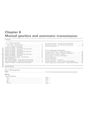 103
103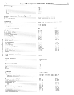 104
104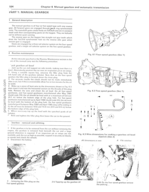 105
105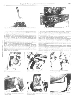 106
106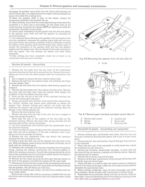 107
107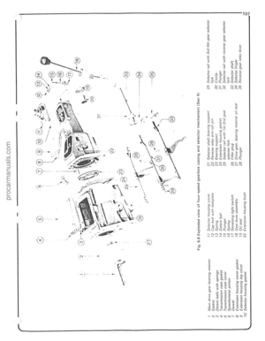 108
108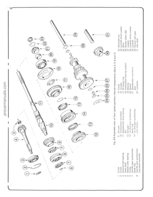 109
109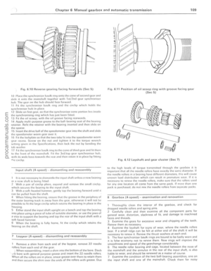 110
110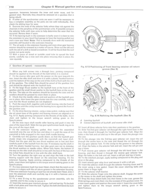 111
111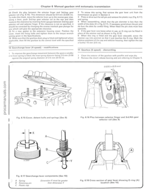 112
112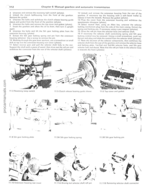 113
113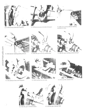 114
114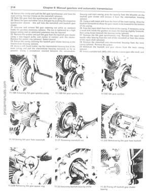 115
115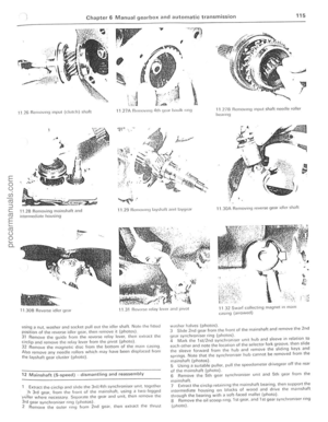 116
116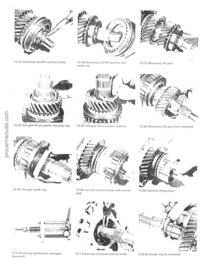 117
117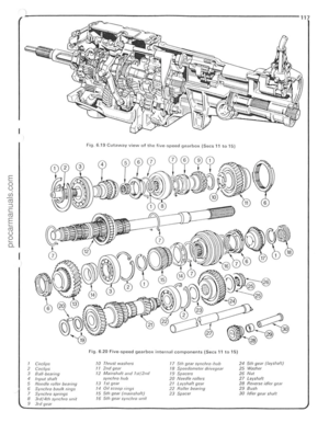 118
118 119
119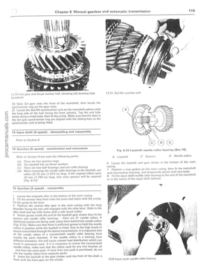 120
120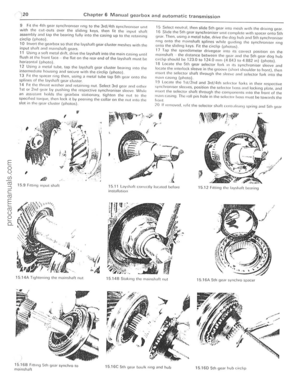 121
121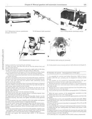 122
122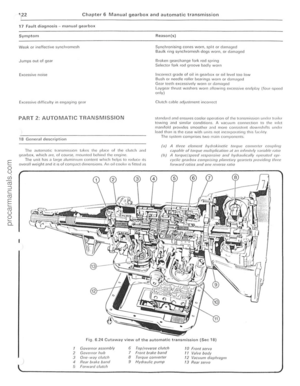 123
123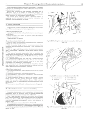 124
124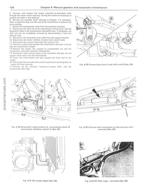 125
125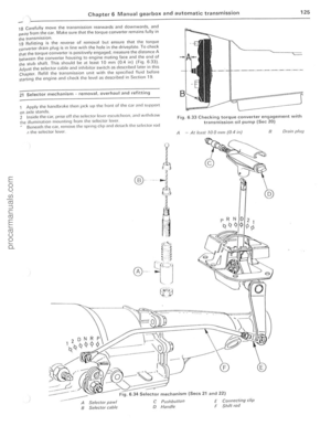 126
126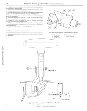 127
127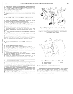 128
128 129
129 130
130 131
131 132
132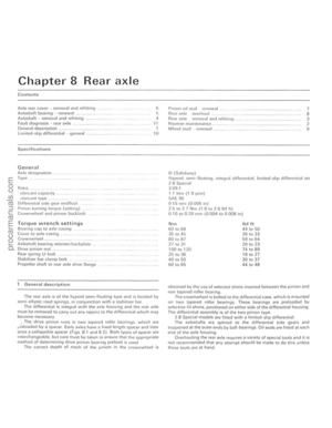 133
133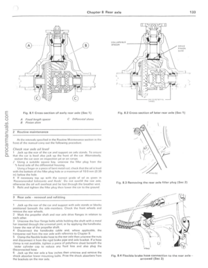 134
134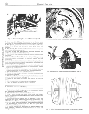 135
135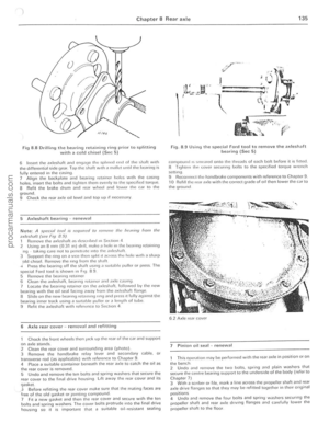 136
136 137
137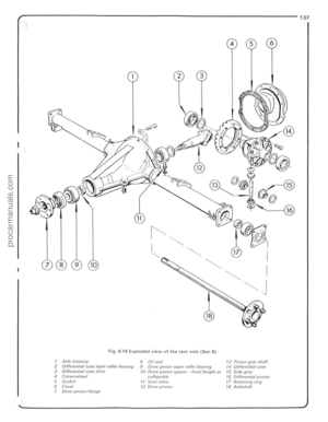 138
138 139
139 140
140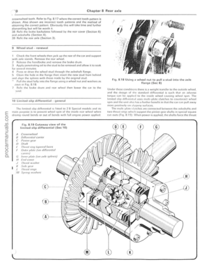 141
141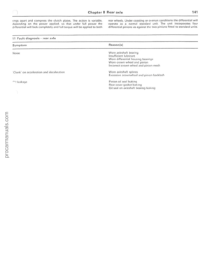 142
142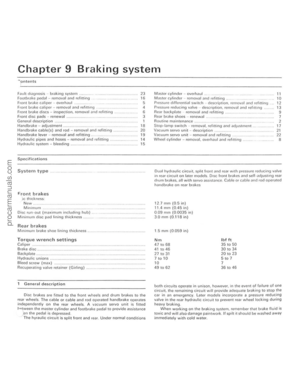 143
143 144
144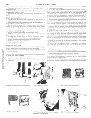 145
145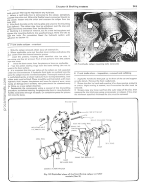 146
146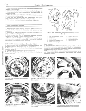 147
147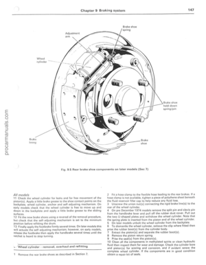 148
148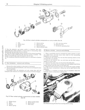 149
149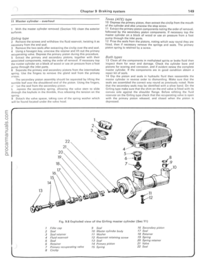 150
150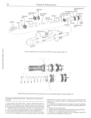 151
151 152
152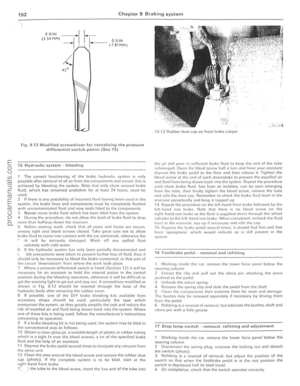 153
153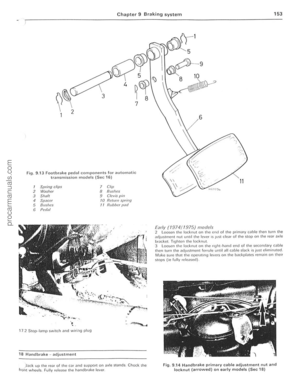 154
154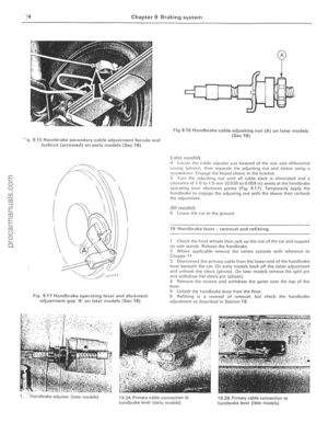 155
155 156
156 157
157 158
158 159
159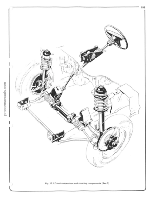 160
160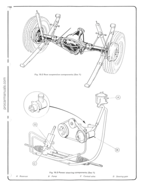 161
161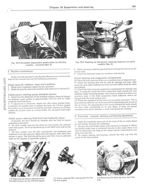 162
162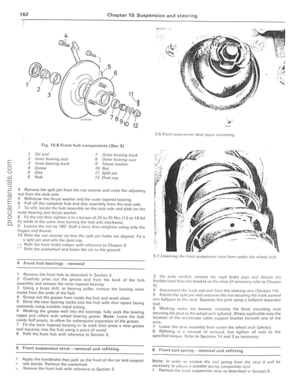 163
163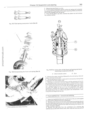 164
164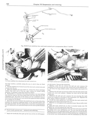 165
165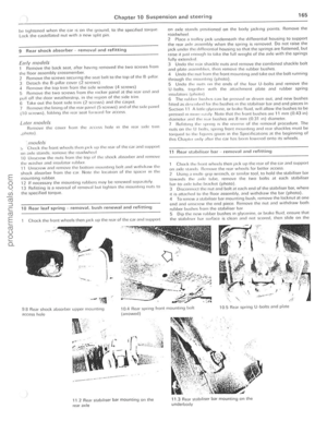 166
166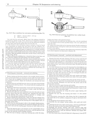 167
167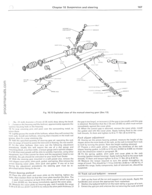 168
168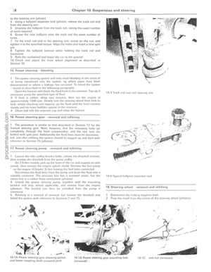 169
169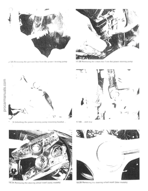 170
170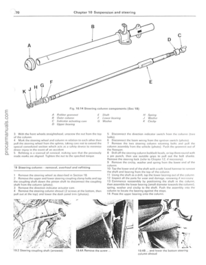 171
171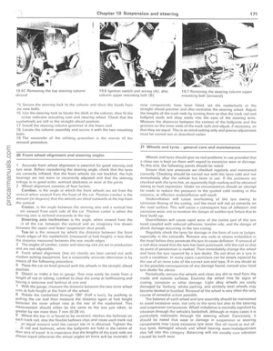 172
172 173
173 174
174 175
175 176
176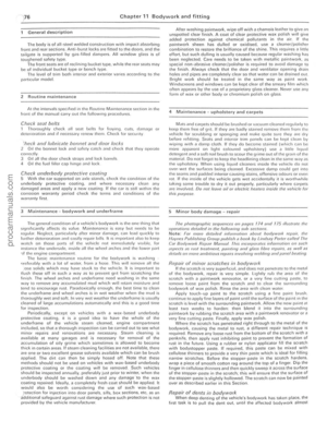 177
177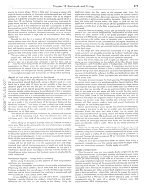 178
178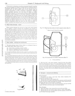 179
179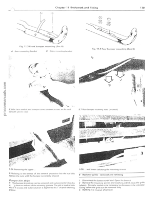 180
180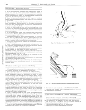 181
181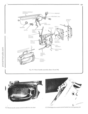 182
182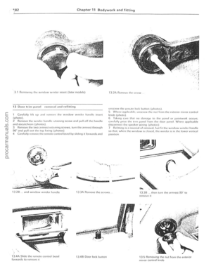 183
183 184
184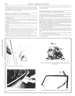 185
185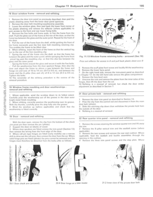 186
186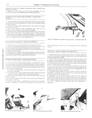 187
187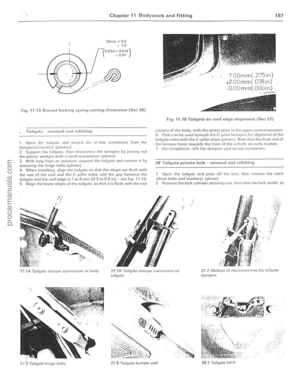 188
188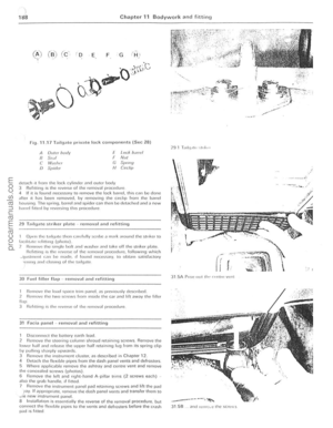 189
189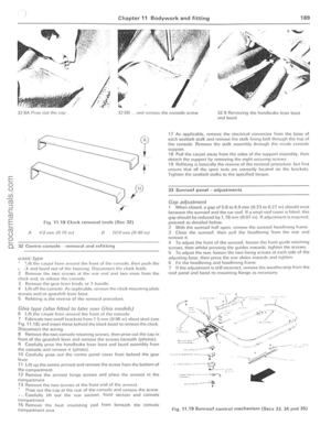 190
190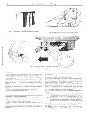 191
191 192
192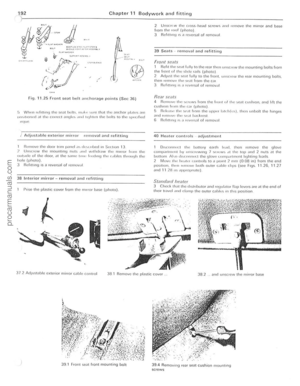 193
193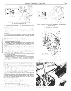 194
194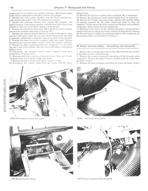 195
195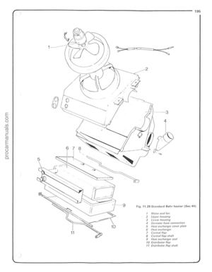 196
196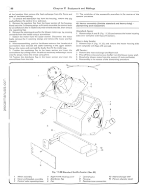 197
197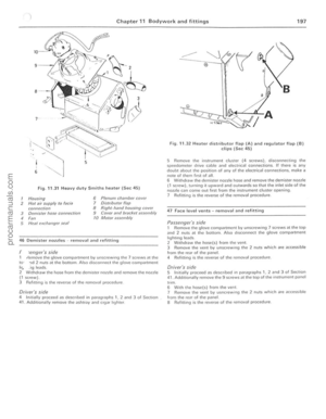 198
198 199
199 200
200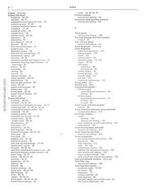 201
201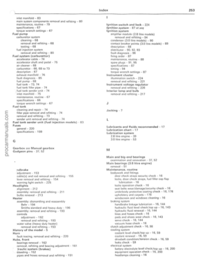 202
202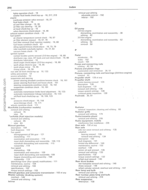 203
203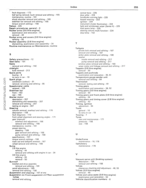 204
204):J @
j •
~ @
@
-
j
@
j
@
,
,
>
.7\(:;;7 j
<;:) :l
;;>
11:;>-
~
@ ®")