Page 65 of 205

A 8 ,,,,,,1/1..·(/ \"\"f lock/WI (LH /lorr.;,,) c Mudd\",\" SIIIIJ!III./
1 2 F\"n hub bC1lr illg (3.0 litre engine) _ re")
64 Chapter 2 Cooting system
FiO_ 2.6 Rernovino tho viscous drivn '"n (Sec'1)
A 8 ,,,,,',1/1..·(/ ""f' lock/WI (LH /lorr.;,,') c Mudd"," SIIIIJ!III.'/
1 2 F"n hub bC1lr illg (3.0 litre engine) _ renew .. ,t
Remove
th e drivel>el t (Section 10) then unholt th e 1,111 and pulley. Where il v,scous drive 1,111 ,s j,ued. reler t o Sect ion 1 1. but where ,1 st .. m d;ud Ian is I.Uo wh,ch 'C1.lIllS Ihe hea,ing in Ihe housing. then I>'e~s Ihe lJ(:arrng . expansion pili\) ,lnt! hub oul 01 the hom cover >1 Press Ih e sh"lt o"t 01 Ih e huh 5 Prcss a nnw sh alt ;1Il(i IlCil""!) as."emh ly 01110 the hOIl5'I1U. so Ih;,t thc CUCIo,) ~I'OOVCS me "' ;,hUrr",err l .. ,n il leI'l Irw c,,,.:IoI) G Pre% on lho h"" 11111,1 ,ts hont lace IS 8581"'" (338 ,n) f,olll Ihl1 tc,l' f;lce 01 Ihc fro nt cover .
7 F,t;r new a~lr.'I1S'OIl "Iug 10 Ih e 5h
"', '
-.'. c
'
13 3 Disconncchng the wiring hom the l(,rllp .. ",lh "C " .. "tic sellt!.:: . WI't
13 TClllporll\"ro !.F'lIgo sonder ullit -rCr1lov(l1 (lnd refilting
Th ... ICIU IIC'J\U'C UauUc scndc. UII '\'S IOCillcd all the ou\le elbow ,II the f,ont 01 t he cnglllC. 2 H(llc r 10 S "C 110n 3 .. nd d';lllllhc coolm9 system s"H 'Clcrllly 10 bWl!! I he level hclow the auilel elbow 3 Disconnect the w irmS) from the unit (photo)
14 EHpimsion liHlk·· .ernOllill .. nd Icfiu ing
Rohlf \0 Sec tIon 3 "nd d'i"" the coolm!1 system suH,c'Cll1ly 10 hun\] the IOllel billow lhu ""honor la p hose. 2 Unscrew the cross ·hcnd rI10urliing screws ,lfl(t 1I1I the lank from t ht: lIIi1cket (photo).
3 D,sconeet the hoses .. m d remove the e~p;ms'on wnk (photos) 4 RellwnU IS iI reyer s,,' 01 re moy"l. but rel,n th e coohng system as oescr ibeu 'n Section 5
142 Removing th e e~pansion ta nk mounting soews 14.3A Disconnecting the side hose ... 14.36 ... and bottom suppl y hose flom lhe
c~pansion t"nk
procarmanuals.com
Page 66 of 205
15 Fau lt ui(l9"0SiS ~ cooling system
Sympt o m
Overhe
En\lIlHl !!ms too cool
loss of COOI,llll
...
Chapter 2 Cooling systern
Reason{s)
Insuff ic ienl coolant Drivehel t slrppinu R;JdralQr core btockcI .1. or H"lIe rpSI"tled Air lock in cool lnll SySWIl1 W mer hose Coll.1psed, or linked, ''''red",\) flow TherllloSI
T hernlostat dtlf.!ct,ve , (), 110 Ih,:flnosut W,ol1n Ihe"Il
Dcfe~llve p,ess",e cap l,:akln\l hos,!s leak 111 ,ad,mOl. 01 hen"" tOI() TherrllOsl,lt or 111111111 11~I~l~1 In,l k Blown cylinder h'~ild O.l~l." Crn ck(!(1 cy"nd~( bfock, 0, h(:"d
65
procarmanuals.com
Page 67 of 205

,
i
I II
Chapter 3 Fuel and exhaust systems
Contents
Pari A: C,UbufCIIQr system AccchmllOf cable -removal .1n( rerilling , ........... , ...... . Accclm<J1or shMt ,lOr! pedal -remo\"nl (Inc!")
)
,
i
I II
Chapter 3 Fuel and exhaust systems
Contents
Pari A: C,UbufCIIQr system AccchmllOf cable -removal .1n( rerilling , ........... , ...... . Accclm
SI}ecifications
PMf A: Cilfborettor system
Gctwrctl System 'Y lloC
Fuel pump delivery l)reSS\lrc .
Fuc l I,ln k c,lpnc,'Y .
Cilrhurcttor lytle Tluol1le baf!el dranwtcr
Vcnlull d"ll'ICICI
Mainjct: 1 !I71\/1975 1976 onwards Idlong speed: 1971\/1975 1976 .............. .. 1977onwilfd5 FilSI idle speed: 1976 1974/1975 ilnd HI77 onwilr(ls
Floal leveL: 6111SS lIoal
PlaStic float
Floill Iravel ...
CO %
111 idle: 197<1/1975 1976 1977 oowards ......... ........ , .................... . Maximum choke vacuum p ull down. 1974/1975 .......... ....... .. 1976 1977 onwards ............... . Choke phasing: 1974/1975 1976 .......... .. 1977 onwards,
17 18 3 7 8 20 21 5 6 4 14 13
16
15
1 19 ,
9 12
Weber calburellor
P.1rt 8: Fuel injection system Accelerator cahle -removal and wfl1l1n!J ' Au cleaner -Icmoval ilnd lellll,O!! E~h.1USI maOifold Icmov,ll and whllm!j
Exh,luSt system .. lemoval ,1nd rnf,ttin!1 Fuel l:lnk. sCIld el utUt and follel l"floC !!fmc.,,1 Gene.;,1 descflpt,on
Irlle nuxture • ,1d/l' Slmenl ..
Inle t man,fold .• emoval and 'ef,nn,!]
Ma,n systcm compo nents .emoval and rd,ll'n!) nouline m.1jnlcn,lnce .
P.1r( C: F.1l1ff di,1gnosis Fintlt d,n!]l1osis .. fuel syslem (cadJll,ello,) Faull d'agnosis -fuel system (fuel injeCI,on) ,
11
"
:12 33
Dual vcnlu.i downcfoa"llhl carh,",cl1or. m~IHI"'Ci,lIv Or.cHnlcd (hap'" .agm luel pump. tempcrilh rrc cOllI/oiled air clenne, on sallHl "'0111:15 02510 0.35 kgl/cm' (3.7 1 0 50 1I,l/ln') 580 Il1re (I2 7 1)011)
Weber (Iunl venturi wilh autorn;rt,c choke 3801111 27 nun
1450101 or 1<12 mill 142 mm
800 J. 25 rpm 825 1. 25 'pm 850 l 25 rpm
noo ,., 100 rpm 2000 ± 100 rpm
40.0 mm (1.575 in)
3 4 .3 mm (1.350 in) 12.5 1. 0 .49 mOl (0.492 L 0 .02 in)
2.8:l. 0 .2 1.75 10
5 .0 1 0 .25 nun (0.197 7.0 J . 0 .25 mm (0.276 5.5 :t 0 .25 mill (0.217
2.3 ± 0.25 mm (0091
, 0,01 , 001 , 0.01
± 0 .01
3 .0 :t. 0 .25 nun (0 118 ± 0.01 2 .8 :l: O .25mm{0.110 J. 0 .01
in)
in)
,n)
in)
in)
III)
procarmanuals.com
Page 68 of 205

Chapter 3 Fuel and exhaust systems 67
Torque wrenc h setting s Fuel P\JlllP Inlet n<llllioid Swgc 1 Swgc 2 Swge 3 StJge 11 (<lhe, runninu enome for 15 minutes <II 1000 rpm) Exl1;lllSl n1<ln,lol")
)
Chapter 3 Fuel and exhaust systems 67
Torque wrenc h setting s Fuel P\JlllP Inlet n'
Pari R Fue! iniaclion syslem
G ene ra l SyS1c'" Iype Idl e sp ce d CO "o, V;1CllUlll ~lIprly IUPC (10111 th,: h<:.11 ~Cllsor Oh~r.rv'J Ihe O,) CI; ,hOil Olillc U;1,) villvi) whll!) ,Ilhe s,.,mc hn~c ;)P")
I,
68 Chapter 3 Fuel and ClChau st systems
14 Dlsco""C(:t lhl) V;1CllUlll ~lIprly IUPC (10111 th,: h<:.11 ~Cllsor Oh~r.rv'J Ihe O,) CI; ,hOil Olillc U;1,) villvi) whll!) ,'Ilhe s,.,mc hn~c ;)PpIY"l!1 SUCtIo n 10 Illu cnd 01 lhc ~"ppIV plpn It Ihe 11;111 v,llve 'C~1"'S closed then CI!lu:r tlw (i .dplu;)!l11l or 1110 flap V"IV~l IS 1 ,I\Jlly If thl) I lilP now opf;n~. Ihe f;lUII 1":$ III Ih,~ hea l ~(:n ~o(
3 Air clear -rCllloval nml le fittinu
1 Q,seol1ll(;f:l lhe 1I,,1h !IY 2 Remove tli' l two n"l~ '<:t:lII,n!l 111".111 (,"'.III,,, lid "nt! ",m""" II,,, hd. til ... " I,ll" OUI 11", "" 1.1,',,,,.., 0;1,,11\,,111 3 Kuuc.k '>.ILk lh" I"", Iud. l"hs _mel 'CIIlU"" Ihe toUl Ilul:> so'' tuH1!! lh,);oll ch',IIlt" if) !he r.;Hhu"·lw, lu>
4 Funl III "lIP Inst "'\1
H Ih.·", .11" .. II ""Y'"'''' 1",,1..~ " 1",·I"",,,,,,y •. h d).. .. I 1111"1 I""" P "I~",'I"'" ':,111 I" , ",.,11" I,V ot"".""" .. ,.I"I~1 110" ",,11"1 1"11" "I II ... It ... 1 1"""1' .,,'U I '.(""","'I",!) II", 11111"1' OI,lh' l I,y., I''''!III, (,I 1"1,,, I"" ~II.,~" I." :' Cr.,,,1.. 111" ""!I"'" .",,' /,h~",\"" ..... 1"·. 1"" _, "'''''1 .. 1 p,'III,1 '''''''', .... I",,,, .h" '''''''I' .",,1"1 .,11111" I''''''''y .. , .. ... ,,,' :1 To c.h""k 111.11 II,,! I''''''P ,<; w.II"" 'h ~p""oI" .'IIUIl. ,,,,,,,,,,, ,1 .' p.e"~",,, !la,,!!,! 1 0 th,! IU""p outkl D'M·,"''' ... '. t III" II r ","", hom 11", co,l. c,;ulk th" ""!)"l{, ;11111 UhM"V" wh",h'" Ih" 1>\1,1,,1 1''''';''''111 " ." SllCCd'e d
5 Fucl purlll) dc,,,,illg
D"I,'I:II (h .) 1",,11111'" 10",,, II,,· 1"""1> ,,,I ... lui", 2 Umlo ,IIlIt """("'" lh,' ( •. ".", '~" ...... _ .. "t 0 ""'1 .""t t.!1 "tt lh,· .... ~III".· .. 1 "''1'. 1,lk' '''Ht ,.",,1 :l 1 t""oU~II,ly (.1""" 11", ·,,-ltll"':I'1 "tl'. 1,110;' ,11,,1 III''''t''''\) ,.1,.11,,1,,·, U~"'H a 1);ou'tl>l,,·,11 ,tlHI ( .11"", 1";h"II() '",n<) "" "ny ",·,111"(:1'1 ,I In ,,,,,,,,,,,,,,101,- " tt", "'''''','! ""qll"IlI;" !to ,h"m.IIIIIII'H Dn " .. 1 UVI""!tl'I"" II,,, '.""1", '.,.,.,,\' .• ,; '( (",,1<1 (h~t'''1 tlon ~.,(t llw,"1 ("'t>
6 Fuel P""'tl ,emovnl ,md .uliuiny
L()U~"II II", h""l! ,.ht ... Io<)l1l Ille IWO C(Jlln," (1011:; ')" It\!! P""' P ;,,,,1 ''''"0~C Ihl! ho~" If "'''"1)<,<1 IVp" d, .. ~ ,,,e I'lh .. '<:I cu, Ih,-m Iol'(' .",d H'lti.,e.C lh"m w'lh ).C'l'W lH'" • . ht> .. 2 Undo ,lnd "'!II(We (h" [<\0 nul~ ""d ~fI"'l!1 wn"h,,,~ senor'''!! II", jllllnp to (li e 1"11"'\1 rI"'" H!ull'(11Ih' I,uml' nil nCIll()'" II", !I"~~~I 3 n(:l.tinlH lhe 1""111' 'S the '(:YI:'~ 0' '(:11101';11 . hUl de,H' lhe ,,,.,,\11\1 ',lC",S ,lIld 1'1 " r"' ..... 'I,l~kc(
7 C;orbllrnU or · gCnc'ill
'Th" c,,,hu .. ,uu< IS nllh" \Vclx.r ci .. ,,1 "CIll,,1I (lownd';1uuhl lVI)C Willi ;111 .1II1UI\1;.U<: ('ho~ (~ 10 (:nsur" C;1Sy S.,\lIII1\1 100'" cold The m,un ;Ultl
IItim U sy~",,,,s ;IIe dup"t;~ I1 ... '(I. p;,ch b.1 .. cl h<1Y1I\9 S('j).lf<11e SVS1(:II1S supplied Irom 11 (;0"'111011 110<11 ch,lI1'u." A S'"(JtC ,'lcd':f<110' pump 01 Ih~ dJi)ph"lYIll lVt)C supphes hOlh b;lr!
Ih'Oltl(l hnrrch, trl.1m YenlU" ,1nd ;lceel,,"IiO' pump ""dy ThC,e ;lJe two tl"01l1" ~p'nt!l,,~ ...... hoch ;"tI IIIU!rconnc cled I)y U
.
3 2 O,; ,ur;om 0 1 nir tcmpcr;ohorc contro llC d ilir clcnn.] r (Suc 2) V.I<: IIII11! /",.1,·
f)""d".IfltJJ lllUl f),.II""_"''''
(A j
()
1 1"1:'1' V;,'~!! I/ul ;'" /I"IV
FiU . 3.3 Air c lcm'er (A) (Sec 3)
(c ' ..
Fig_ 3.4 Fuel pump filter rcmo",,1 (Scc 5)
8 c Pump body
procarmanuals.com
Page 70 of 205

-
Clwpter 3 Fuel <lnd exhaust systems 69
The fully ~u!OnHIIIC choke system IS lor.olle(l 011 lh'~ \"oill-hami side 01 t he CnUUlCltor hody <ll1d COllp\"ses \" h,·mct<lllic SPllllH nud ,1 link")
)
-
Clwpter 3 Fuel
The fully ~u!OnHIIIC choke system IS lor.olle(l 011 lh'~ "oill-hami side 01 t he Cn'UUlCltor hody
a Carburcltor -rClllovill
1 Disco nnect the Iwltery . 2 nc",ovc Iho) "" cle
5 Disconnect the fu,,1 f"ed ilnd ,(:t",,, plp"S I,o'n til" C ... I"'H-tt,,, If •• cl, ,,,pf,, IIYI' " hose dan,p IS l'ltr~d, CUI II,e ,: 1""'1' II> ""n,w" ,t .",,1 "·'''·W II wLlh
SpeC ifiCatiOnS and wlrt ,III the 1r0$CS Top u p til" ",,,,I"'!I ~y~!t:m II necessa.y. Adjust the ,die ,;p,;Old ;0111 IIlIxtuw a,; d"·,,.,,lred II, 5",.1 ,,, " 12 .
Fig. 3,5 U·circlip 011 the choke operatil\g link (Sec: 9)
A /I
Fi9 3_7 Upper body components (Sec 9)
Flo,lI telaininy pm Ftll.'t c o NlJcdto V;I/V(!
POWCI v.1lvc
9 Weber Cilrhurettor -dismilntlinu [lnd reas~ernhly
Note: On 1977 mod(!/s onw,lf(II /lIP. cmlll/id/ot 11,15 ,1 '/Jy PilIS' tdle IIdIItS/IIIY SP~'W willch IS sc,l/r:iI //I l!lodl/cllOn wl/h <1 willie (}f ljlCY 1,/,'sIIC (:,11' UlI(ler /10 CItC(ff!!s/a/lces should {/II.~ SCI('"W h e /,)t!J/JlNl'd wi/h (Fly 322) 1 R(!II1Ov(! the C.1,h"n;llor I! O"l th e ':Ol!)""' . ,1~ dr;w,lp.oI ,n Section 8. an d cl(!,lIl th.) f:ilrl""etlor extC"Of w'lh 1'.,['01 or a walt' soluhle t"OI",,:l;\,y 1'/,,;)11(:1 J. C;, rdully I"'S" 0,,1 Ihe U'CIIClrp w,th a hC,(lWII"v" •• lIul ,h~COIUlo:cl til" '.ilok" pl"w oj)l:(allnulrnk :I 1\""10\"" tire ~I X ·,,:,,'ws ;'"It ,i,-(;" .h II" , GIl1"""llor "Ill"" body. ·1 Uns';",w llr,) h'n~s nul locnl"d:ot th" ((",I ,nwk,) .'nd d el.1cll Ihe flU'l
Iolt"1 (; T"II Ollt tlo" lIo;i! ,,,t.1"lII'!J pm. ;,nd dd.1{,1r II,,) 110;11 ,Hl d needh~
v:otv" I, R"",,,v,, tlon th,c" ~c,,:ws and d"t.u:1r tlw po","", valvc d';lpl"a!)1ll .'~h,,"'tJly 7 U"hl:",W thn ncedle ~"Iv" ho,,~,nu 8 U"suo:w the It)( and Io:t pt"\Js I. o r" til" c."jJ\""l1m Imdy. not"l\) th .. , p"~.'I'o"s III wh",h 11,,;y ;0,(, f'lll:d ~) I~l"ll()v" (h" two cn ,"b,on luhes ;011'" ,,,'IIOVIII\) the two lll,lIn "" l"II rt<.:t,on t,;ts 10 1l<:!lIUVC lorn sr.'l:ws. t;JkC nil II", ,1co:"I,;r.lto , j)"Il'P co"", ,,,,d ,,,,,,,-.vOl ttl<, d',Ij,lua!l1l> ;Hld 5P(in'l SUlul,,
"11,,1<;1, ','rI"'v\! tile '11'tl·~tall d,.lt>lua~I'" 1 1 CIo';j1l .,ll ttlC compontnt s ;oml Ih,,' (.:n,;w" Ihat the lets ,\10 ,u",I".t,,,. :t"III,y I,tow",!) t IHOI,!)11 Ilw'I' I J. Ca,ciully ';C,(,W ", Ih e moxtu,e sc.ews Ul\lI( (,aeh 01 Ih cm con1.1cts
Fi\j. 3.6 Removing the upper h ody -nrrowed (Sec 9)
A II
Fig. 3,8 Jet locatiolls (Sec 9)
Mwn ICIS C Idlc ICIS Air COtt~'CIIOIl ;"IS
procarmanuals.com
Page 71 of 205

70 Chapter 3 Fucl and exhaust systems
liS seatmu Note ,1nd reco.d the number of lurns, so th,11 the screws can be relltted 10 their orjuin~' settings . Unscrew cilch screw fully and remove it and its SPfing . 13 Che<:k the lIoat
COlleCtIOn Icts Hi Rein tho power valve dlo'Jlhr"gm nssembly ~s follows. Loosely fIt Ihe Ihree rtrnplungm ret"iIlIIlO screws. comp.ess the return spfln!! ensu"o!) tl>;)t the dl"phr"W11IS 001 IwislP.d Or dlSlorted Ihenl;\Jhlen Ihe scrells ,'mf Ide,lse Ihe SP'1I1!). Check lor correcl IUllc lloomo !ly push Ing Ihe rtl,ll )hr"IJlll down nnd ,hen blockllig the:m hleed holll w,lh ;J f,nue, I1cfcnse the d'ilphr;JUI11 whde 51111 keeplll!J the ,lIf holo blocked [I the fhilPlu"~Jm sl,'ys down. II hns Willed j)rope.ly to Its housing 17 RefIt the Ileedle v"lve hOIJSIII\j, ncedle v;Jlve nnd 110,11 nssemhlv 10
Fig. 3 .9 Emulsion t u bes (V) (Sec 9)
Fig, 3.11 Removin!J tho IIlIli'Slilll dillphragm cover (Soc 9)
Refum sWing 8 Cover
the upper body. 18 Adjuslthe flo." level settings, fi,slly w;l h the upper body verlical .md I he needle villve s hut off lithe meilsurerneot is outsIde Ihe IInlllS given in the SpecifiCcnd Ihe Ing umll Ihe SCltll1g IS correct ,,,ul recheck. Far bOlll 11m flam leve l ild!lIstmCIllS Ihl! lIJlflCf body g,~~k'" muSI be remove<1 . 20 Refit Ihe fuel inwke "Iwr ilnd loc.11if1{1 11111. 21 Posilion Ihe Uilsket (lnd relIt the c(llbu.ellor UP1Xi' hody M,lke SUII' Ihill the choke link loc;(1\es through Ihe upper hody correClly 22 Recorlllecl the choke link Mid secure II wllh IIIIl U·clrp 23 AdjuSI Ihe Ih,o\lle 1)1(lleS lor synch,onrlilIIOIi. Wme! h"ck Ihl! .. II" screw unlll II,s r.le,1r ot Ihe IhrOllle mcr.hmliSI11 ilnd Ih{:n 101)5'''' Ill" synchronililllOn "dlust,nu sc.ew. Hold Ihe "ulo·chole pl"tes '" ,m open POSItIon, flIck Ihe Ihrollle ilnd ,,1I0w hOlh pl,1les to r.1o~e IIIlIy T"p bOlh pliltes 10 flnSilre Ih.11 Ihey h,we clnsml r.nl1lph~I{:ly ;111(1 liI(:" ll!Jhlcn the synchrorll~il1l0n sc.ew. To chHck. j)a,lmfly open IhH Ih,nllll! uSll1g the 1(110 sr.rew, SO Ih~1 IllIlre IS n clealanCe! of 0 5111111 (002 HI) betweeo olle of the Ih.011le j)l alL's (lnd li S holC ChHck Iha l the mh,·, plnle hns Ihe s~l11e open;lI\j
Fig. 3.10 Relllovingllie IIccelcrillor pump cover -(lrrowcd (Sec 9)
..
Fig. 3.12 Accelerator pump components (Sec 9)
A B Covcr Diapl/mom c RC/(lfll swing
procarmanuals.com
Page 72 of 205
 Chapter 3 Fuel and exhaust systems
FiU _ 3.13 Components to he checked (Sec 9)
A
8
C/u:(:A fur wP.olf alJd (/illllif/I.l Clwck (If .~/I\"lIitJfJ
C CI)(xk for hd,ill{J {) Check (Of spfrll")
) Chapter 3 Fuel and exhaust systems
FiU _ 3.13 Components to he checked (Sec 9)
A
8
C/u':(:A fur wP.olf alJd (/illlli'f/I.l Clwck '(If .~/I"lIitJfJ
C CI)(xk for hd,ill{J {) Check (Of spfrlling
10 Weller cnrhurettor ""tom,lIie choke - rcmov,]L overhaul
and refitlinu
1 DlsconlH!~1 Ihe i)illicry nC\j
3 UnscI!;w the contlC hoi! ""d remove the cover. 1 Remove the three SCfClWS. dewell the housing
5 Detach Ihe interna l hCill shield . 6 Remove the smgle U· clip and disconnect the choke plote OpCfilting link, 7 Remove the three screws, disconnect the choke link ,It lhe opefiHing lever nnd dctilCh the chokl:! assembly . 8 Remove the three screws ric"nts dlllinU
le"sselllhly. 11 Ik"ssemhle the choke meCh'1I11SI11. 12 Relit ll1e v"CUUIll til"phl1'lI)lIl alld hOUSII1,). enslllinu th"t lhe (hilphl,l()fIl IS lIolt before lile housing IS fllted. 13 Ensure thm the O-IIllg is correctly locmed in the choke housinU then reCOllnect the lower choke I",k Position the assembly and secure il WIth the thr ee sClews . ensure thnt the upper choke link loc"tes
cOlrectly tluouUh the c"rlJlJretlOf body 111 RecOllllec t the upper choke Imk to the choke Sp"l(tie. 15 Check the V"CUUIll pull· down
Sect ion 11 1 G RelIt Ihe mlern,,1 heat shield enSlllinu that the hole in the cover loculCs correctly onto the peg C[lst III the housing. 17 Conllect the bi·mewl Sp"llg to the choke lever. position the housing and loosely lit lhe Ihree relnining screws. 18 ROlnte the houstng untIl Ihe marks ,lre "Iigned. then light en Ihe three screws. 19 Refll lhe cover logether WIth [l new g
11 Weber carbur e l tor automnt ic choke -adjustment
Note: lile pfOccc/
bccn rcmoved 1 D 'scOllncct Ihe bn(lcty canh lead . 2 Rcmove the illf cleaner. ilS deSCribed in Seclion 3.
.l.I. .... , •• ,. ••. • .. .• . ,,~ ......... , •• , •• .;..,.: .•• ' •.•••• 1 . ;."
.,.', .,1,,/. 1,,' .. 1 . .. . , 1.,.: .. 1,.1.1,.1 .•. : ...
J
Fig. 3.1 4 F loat level adjustment t
Fit!. 3.15 Automatic choke housing re taining screwsilrrowed (Sec 10)
.------
./ /' (
Fig.
/
3 .16 Automatic c hoke h ousing alignment (Sec 10)
A Rich c B Normal scl/lllg
marks
71
procarmanuals.com
 1
1 2
2 3
3 4
4 5
5 6
6 7
7 8
8 9
9 10
10 11
11 12
12 13
13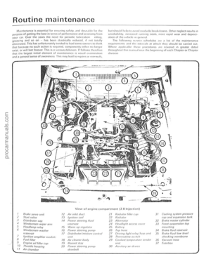 14
14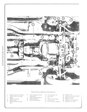 15
15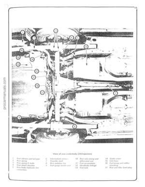 16
16 17
17 18
18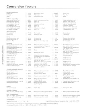 19
19 20
20 21
21 22
22 23
23 24
24 25
25 26
26 27
27 28
28 29
29 30
30 31
31 32
32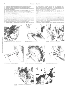 33
33 34
34 35
35 36
36 37
37 38
38 39
39 40
40 41
41 42
42 43
43 44
44 45
45 46
46 47
47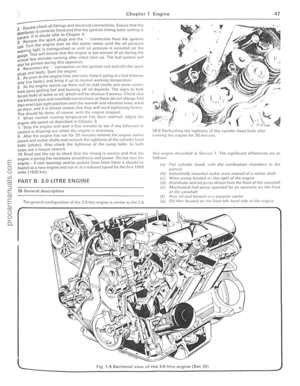 48
48 49
49 50
50 51
51 52
52 53
53 54
54 55
55 56
56 57
57 58
58 59
59 60
60 61
61 62
62 63
63 64
64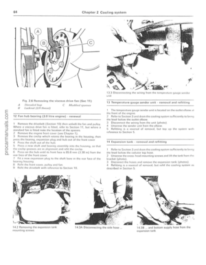 65
65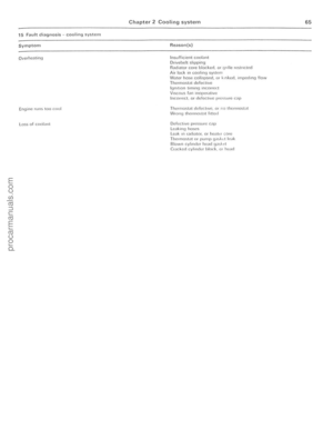 66
66 67
67 68
68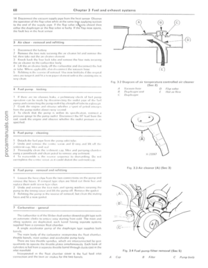 69
69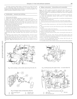 70
70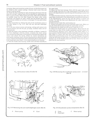 71
71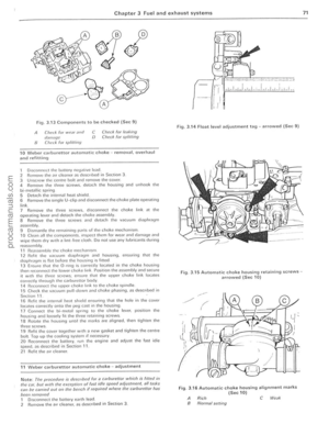 72
72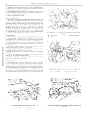 73
73 74
74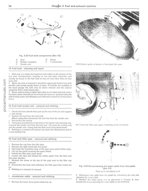 75
75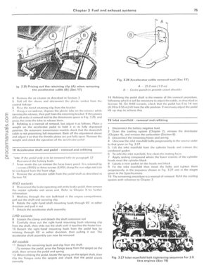 76
76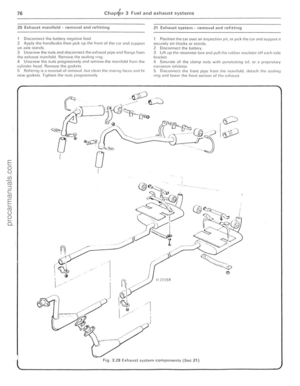 77
77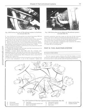 78
78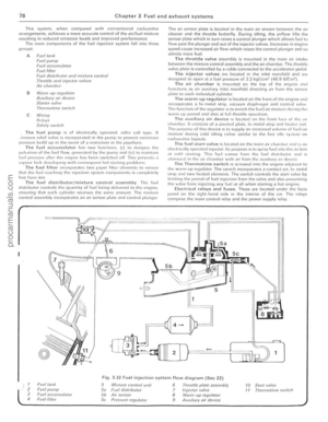 79
79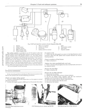 80
80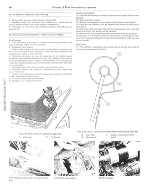 81
81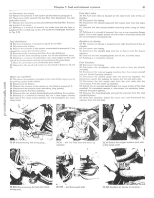 82
82 83
83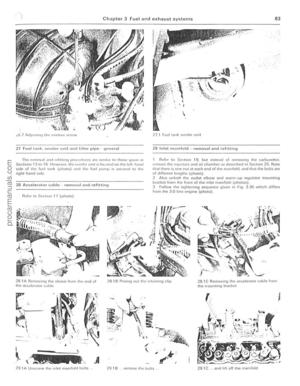 84
84 85
85 86
86 87
87 88
88 89
89 90
90 91
91 92
92 93
93 94
94 95
95 96
96 97
97 98
98 99
99 100
100 101
101 102
102 103
103 104
104 105
105 106
106 107
107 108
108 109
109 110
110 111
111 112
112 113
113 114
114 115
115 116
116 117
117 118
118 119
119 120
120 121
121 122
122 123
123 124
124 125
125 126
126 127
127 128
128 129
129 130
130 131
131 132
132 133
133 134
134 135
135 136
136 137
137 138
138 139
139 140
140 141
141 142
142 143
143 144
144 145
145 146
146 147
147 148
148 149
149 150
150 151
151 152
152 153
153 154
154 155
155 156
156 157
157 158
158 159
159 160
160 161
161 162
162 163
163 164
164 165
165 166
166 167
167 168
168 169
169 170
170 171
171 172
172 173
173 174
174 175
175 176
176 177
177 178
178 179
179 180
180 181
181 182
182 183
183 184
184 185
185 186
186 187
187 188
188 189
189 190
190 191
191 192
192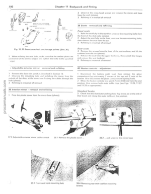 193
193 194
194 195
195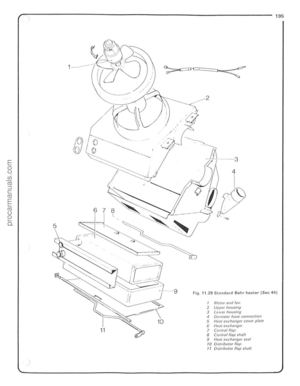 196
196 197
197 198
198 199
199 200
200 201
201 202
202 203
203 204
204
Insuff ic ienl coolant Drivehel t slrppinu R;Jd")