1974 FORD CAPRI suspension
[x] Cancel search: suspensionPage 4 of 205

)
Contents
Introductory pages
About th is manual 5
Introduction to the Capri VB 5
General dimensions, weights and capacities 6
Jacking and towing 7
Buying spare P M 'S and vehicle identification numb ers 8
G en eral rep air procedures 9
Tools and workrllU facilIties 10
Safety f irs t! 12
Routine main tenance
Recommended lullricants and flUids
Conv ersion !,I CIOIS
F aull dlilgn osis
Chapter 1
EIlUlne
C[Hlple r 2
Coolin\) system
Ch
Chapter 4
Ignition sys!Cm
Chapter 5
Clutch
Chllptcr 6
Manllill IJCil,hox a nd 'llltonlil!'!.: lrililsn'IS~IOII
Chopler 7
Propeller shalt
Ch(liltcr 8
IlCilr ilxl<:
Chapter 9
l3ulklilU sy~lem
Chapter 10
Suspension ilnd SluCIIIIU
Chapter 1 1
Bodyw or k and trl1il19S
Chapter 12
Electrical s y s!Cm
In de x
13
17
18
19
23
57
66
87
"
102
12 8
132
142
1 [is
171
196
248
procarmanuals.com
Page 14 of 205

Routine maintenance
Maintenance is essential tOI C"~l"'Il\J sal"I\,.
The 1"II<)wII'~1 Sr:r",,:,~ schedules ,"lJ ol I rS I of the maintenance req
.
,
. . c;~
~--------------------'--~~~~'~
I Br,lke St'fVO uni/ 12 A" mIN duct 21 f/,ld'o,IOI l"lm c:,/, 31 Coohng sys/em pressure 2 Slarl v
Page 17 of 205

" ,
'6 Routine maintenance
)
Every 250 miles (400 lUll) or weekly -whichever comes first
Check the engine 011 level and lOp up " OCCCSSJry (Chapler 1) Check and adlus t lhe IYIC pressures (Chilplcr 10) Clean the windscreen and windows C lean the hcadlamps
Every 6000 miles (10000 km) o r six Illonlhs - whichever comes fir s t
£II[1ille (Clwpter 1) Change engllle 011 and IIher
Cleiln oil flilm c"p Chcck 10 1 ,IllY fluid leaka!)e ,n enUme CO'llp:lnUlCIl1
Cooling syslem (Clwptet 2) Check cool:'lnt level
Fuel syslem (Clmpler 3) Check idh"U mi~lUle (cmiJUiello1 IllUdels onlv) al I"SI se.v,ce ollIe, overhaul C heck idllllg sj)ee d
Ignition sys/Cm (C/I,Wler 4) Clean ,1nd re!)"p Sl)".k plu!)s (.:on!nC ' breilkCl Illudels olllv) Cle an and check d'Shibu\o. C"I). '010'. HT lealls mId co.1 (COllWct
bleaker modcls only) Check elwell angle (cOntact b.e"ke. mo
Bri/king sys/Cm (Ch,1pter 9) Check selva
Che ck hydraulic flu id h,vel
Ch(: ck p"ds :'Illd sho(:s lor wear Check h.ake hllcs and hoses
Suspension .wel stvi'ring (Chi/pICr 10) Check tyres 10' w ear and dam:lge Check steering COmp{lIlCnlS l o r w e:l l "lid d.1nlilue
Bodywork. .111d fittings (Clwptef 11) C lu .. >ek se"t belts fa. we .... damage :lnd secwity
Elvc(ric.11 systcm (Ch,7jJ(ef 12 ) Check Ope.iltoon 01 "Uhts Check wilsher flUId levels Check b.1ltery eleclrolvle lev el
Every 12000 miles (20000 kill) or 12 mOll1hs - whichever comes first
III .1(/(lIlioll 10 Ihe 6000 m/le sciler/Ille
Engine (Ch.1f)ter 1) Check and adlUSI valve clearanc es
r"' .......... ~.~-.... ._ •• -.... __ .... . 3lii1&l •
Cooling system (Chapter 2) Check condition "net tension of 1111011)<1101 dflvehelt
Fllel sys tem (Chapter 3) Tighlcn inlel IIHlnl lold boits/nuts Check vacuum hoses Check e~hiluSI syst em Check ll1r ctonne. temperature cOllllol (,I applicable) Renew fuclllllC ' (fuel injec tion models only)
Ignilion system (Chapler 4) lubricate th e dis'flbulOf (conUlel br eake r models only) Renew the coninCt hu,akcr points (II nppllcJblc) Renew the spMk plugs
Transmission (Chapter 6) Check ool/th"d level Lulmc;ue automatIC 1.,'Insmlss,on IInk:'lue
Rcar axle (C/MplCt 8) Check 011 level
Bli/king system (Chaplet 9) Check v,lcuun' hose
llliJllc:'l1C Ihe handhlake Imk,loe
Suspensioll {//j(J swelill!J (C".1plt~( 10) Check condItIon and hlllSlon o f POWI.II ~I!'tllllli dllvthtl1 (II .1l1pllcal,
Check MlspenSlon 101 we;" ;111(1 d;1Il1.1!)e
Bodywork ,1I)d fillings (Clwpler 11) Check opera lion of all locks Check secu.ity 01 dOOf check sl.aps
LlIl)fIcalC locks. door c heck S\','P5 :'Ind fuel fdler cap flap
Check underbody pr olCctive coalm!)
Electrical system (Chapter 12) Check Opcra1l0n of all eleC111!:al IIcm5
Evcry 2<1 000 llIiles (40000 kill) or 2 yc;u s -\Nhichever comes firsl
III ,1(/111/'011 10 the 12000 111"'1 $d'~'f/u/e
[nyino (CIWpICf 1) f!ell'!W crankC:l $e e""5510l1 v;llve
Cooling syslofll (Clwptor 2) Renew COO!:1II1
Fllel SYS(CIII (Ch, '/pliJr 3) Renew"" II Ih!r elemenl
TrallsmissiOIl (ClwjJWr 6) AdjUSI aulom;1\IC trall5nll5SIOll h,ake b;'IIld
Every 36000 miles (60000 kill) o r 3 yenrs - whichever comes first
III .1(/{/I('01l 10 Illc JJIl'VlOUS schc(/ulcs (",lIc" JJJIJ"ci,bfc)
Brakillg system (Clwpter 9) Renew hyd,auhc flUId
procarmanuals.com
Page 95 of 205

94 Chapter 4 Ignition system
i ' .
. --8 2A Removill{J the IllnSlre dust COve, (28 hl'c Cllume)
./ :,
, , ,
(\. I ,
" 'v
J 2C W'''I1!j connector i'Uld seCUJlIlg screw (lHOwS)
9 Ignitio n timing -adjustment
Wnh the (.lIs\"OuIO' III!Cd ilS dcscllbed OIl SectIon 6, check Ihilt 1Ill! COHCCt llllllng m;l!ks "'0 ;1119110d. 2 To check the ;1111,,11 (5 t;1I,e) setting, .emovc the (I'51"lIu I0' c;lll [11l\( check IhJllhc rOl0' ;lIm IS PO"1I1119 to the No 1 cylmdc. scgmon!.n the Cill) rndlcmed by the sial on the 11m. 3 On the 3.0 lUre engIne the cont,le l poullS ll\u~1 he ,ust SCI)ilril\U'!J Tho e~ilCt Instant C,1" he checked by connect"'u il 12 vol1 lest lamp between the contilC, brcilke r low tenSIon Iemur),,1 iUl(t O,"lh, W,th the iUnilion Oil, tho d is trlbuto. ShOllld be turn ed nrl\,·clockwisc unlol lho bulb luSlligh(s. " On (he 28 li(re enuule the ("gger arms and stator ;HIllS must bc aligned It not. (um I he (hst"bulOr as necessary . !:i Tighten the (hSI"buto. clamp boll and .ehl the cap 6 Set In thIS way the lUlling WIll be alll)'Olmalely co
8 2B UtJlle. vIew 01 the l.imJer Mrn .lrld Call (28 lIt Ie enU"Wj
.1
,I,
.. .."
8 20 Vacuum un.1 sC(:u"ng screw WIth e')Hh lead termmal
10 W,lh Ihe enij1l1e I(lIrng pornt thc \fmlng hgh( at the cr",lksholl1 pulley The wh,le 1),1mte
12 To check the mechanrcat adv.1nce. Increase the engIne speed and note whelher the wh,te malk on the pulley moves away Irom the mark on th e pOInter . 11 It docs the mechanical advance is lunctioning 13 W,th the enOlile Idlmu the vnCU\ Jm advance can be checked by suc kIng the oldv~ncu pIpe that W.1S removed from the carburellOI o r air box ThIS should also c.Juse the while rnark on the pulley to move away horn the mar k on the pointer 14 On completIon remove Ihe timlllU hght and rC(:onnec lthe v.1CUUIll pIpe
10 Ignition illlllllifier module (2.8 l i tre enuine) -removal and rClittinu
Thc Iunitlon illl\J}l lflcr module is locmed on Ihe left· hand SIde of the engIne COnlpar tment. tUSI behind Ihe hOnt suspenSIon strut upper mounting.
procarmanuals.com
Page 152 of 205

-
)
Chapter 9 Braking system
,,-
")_'J ,
: ~~ 11111JIII/IIIJ II /I /III Ii hIIllllIlIlIllllIlll 11111#111111 III! -------
8
9
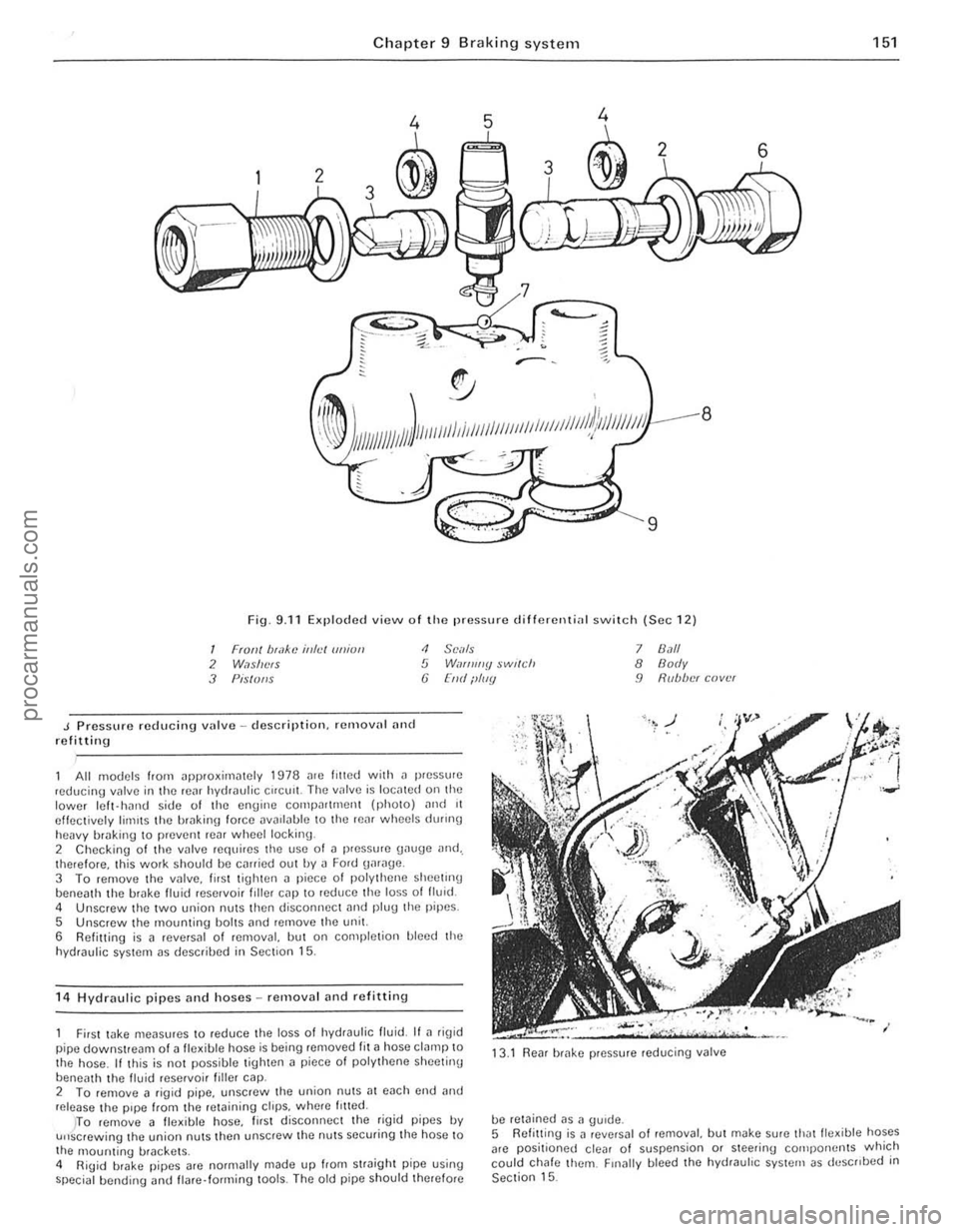
Fig. 9.11 Exploded view o f Iho pressure d ifferenti
J Pressure reducing vulve -description. remalln' nnd refitting
<1 SCi/Is 5 W,If/ll//y $wl(ch (j [lid ilIIIY
All models from ~pproxirniltely 1978 me lilted with il pressure ,educing valve in the rC~f hydraulic Cifelli!. The IInlve is IOCillCd on the lower Icft- hJrHJ side of the engine compn((mcnt (phOIO) ,mel 11 effectively limIts the hrakin\1 force DV
5 Unscrew the mounting bolts ,md remove the unit.
6 Refitting is a reversal of removal, but on completion bleed the
hydraulic system as descrihed in Section 15.
1 4
Hydraulic pipes and hoses -removal and refittin g
7 8.1/1 8 Body 9 R(lb/w( cover
First wke meilsures to reduce the loss 01 hydraulic fluid. If ~ rig id
pipe downstream of a fle~ible hose is being removed fit ~ hose clamp to
the hose . If this is not possible tighten a piece 01 polythene sheetinu
beneath th e livid reservoi r filler cap. 13
.1
Rear brake pressure reducing valve
2 To femove a figid pipe, unscrew the union nutS;]1 each cnd and release the pipe from the retaining ctrps. wh(Jre /riled.
be retained as a gUide.
151
)TO remove 11 fle~ible hose, lirst disconnec t the rigid pipes IN u"screwing the union nuts then unscrew the nuts securing the hose to
the 1l10unting brackets .
4 RiUid brake pipes arc normally made up from straight pipe using special bending <.rnd flare· forming lools. The old pipe should therefore 5
Refitt ing
is J revNsal o f removal, but make sure thJtlle~ible hoses
arc positioned clear of suspension or steering cOlilpo rwnts which
could chafe them. Finally bleed the hydrauhc system as deSCribed in Section 15.
••
procarmanuals.com
Page 158 of 205

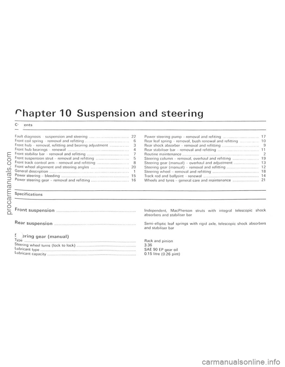
rhapter 10 Suspension and steering
F
Front suspension
Rear suspension
, . , enflg gear (manual) Type ................... ....................•................ Steeling whecl turns (lock to lock) .. . LUbrican t type ............. ................. ...... . lUbricant capacity _ ............................. .
" G 3 ,
7 ,
• 20 1 15
"
Powel stCCIlIlg Ilump .. remOllal ,111(1 fcllting RCiU leill SI)II119 . emoval. bush renewal .1nd Iclottlng Flo;"), shock iJbSOfOO' removal ,m(/ felUtlng , ............... , Rein sl
Steering column -rCmov
Steeling wheel -rCfllov
Wlleels nlld lyres -uencrill CilfC and maintenance ...................... .
17 10 9
" 2 19 13 12 ,.
" 21
Independent. MacPherson strutS with Integral telescopic shock
ab sorbers
Rack and
pinion 3.36 SAE 90 EP gea r oil 0.15 IlIre (026 pint)
i
i.
!
I (
!
:~
I:
II
procarmanuals.com
Page 159 of 205

)8 Chapter 10 Suspension and steering
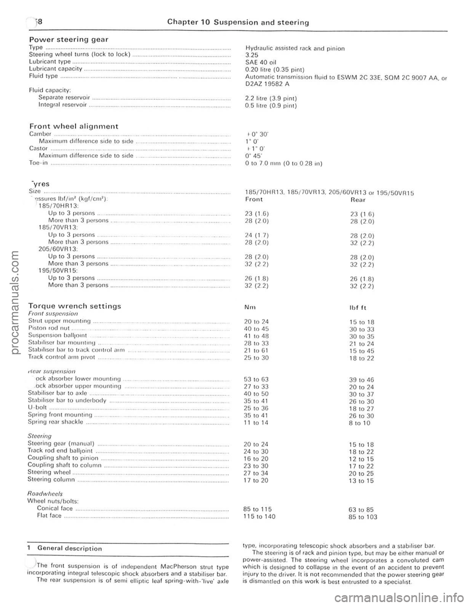
Power steerin g gear Type .. Steer ing wheel turns (lock to lock) lubrican t Iype, Lubricant capacity . Fluid Iype .
Fluid cilpacily: Sepilrilte reservoir . Integli!1 reservoir .
Front wheel alignment C",nbc, M;lXll11um dlffcrence side \0 side C
195/50VR15: Up 10 3 pe.sons . Morc th(ln 3 persons.
Torque wrench settings Fran! SIIS{!cl!siotJ Stlut upper 1110untrng . P,ston rod nut Suspen Sion ')~",{Jont St;rhiliscr birr mount"'lt . Stab iliser h;rr to track control ,)In,
Track cOIHlol ~rrn p,vot
,H'o1( slIspCIlsion od abso,bcr lower mountH'g .ock absorber upper mounting Stabillser bar to axle .. St;rl.lIlIscr har 10 underbody
U ·bol . Sprinu I.ont mount"'g . Spring rear sh;rckle
SINNing Steering gear (m~nual) Track rod end uall,oint Coupling shaft to pinion. Coupling shah t o column . Steering wheel.
Steering column.
Roa(/wiJec/s Wheel nuts/holts: Conicall;rce . FI(lt face.
General description
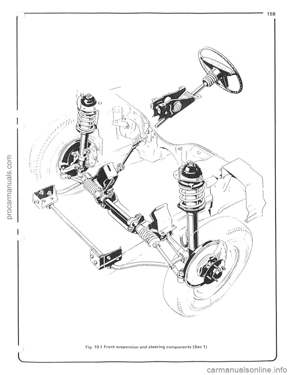
, -'The flonl suspension is of Independen t MacPherson Strut Iype incorpotating inleglal telescopic shock ~bsorbers and a stabilisel b~r. The ,eal suspens ion is o f semi ellip tic leaf spring·with· 'l ive ' axle Hydrau
l
ic assisted rack tlnd pinion 3.25 SAE 40 oil 0.20 litre (0.35 pint) AulOm
1- 0 ' 30' I" O· I l' O' O ' 45' 01070 nun (0 !O 0 28 ",)
185170HR13. 185/70VRI3. 205/60VR13 o. 195f50VR15 Front Rear
23(1.6) 23 (1 6) 28 (20) 28 (20)
2<1 (1 7) 28 (2.0) 28 (20) 32 (22)
28 (20) 28 (2.0) 32 (22) 32 (22)
26 (1 8) 26 (1.8) 32 (2 2)
32 (22)
N'H Ibl It
20 to 2<1 151018 40 to 45
30 to 33 <11 to <18 30 to 35
28 to 33 21 to 211 21 to 61 15 to <15 25 to 30 18 to 22
53 to 63 39 to 11 13 27 to 33 20 to 2<1 40 to 50 301037 35 to 41 26 to 30 25 to 36 181027 35 to <11 26 to 30 11 to 14 8 to 10
20 to 24 15 to 18 24 to 30 18 to 22 16 to 20
12 to 15 231030 17 to 22 27 to 34 20 to 25 17 to 20 13 to 15
85 to 115 63 to 85
115 to 140 85 to 103
type, incorporating telescopic shock absorbers and ;l stabdiser bill. The steering is of rack and pinion type, but may be either m(lnual or power·assisted . The steering wheel incorporates 11 convoluted cam which is designed to collapse rn the event 01 (In accident to prevent
injur y to Ihe driver. It is not reco mmended that the power steering gear is dismantled on Ihis work is best entrusted to a specialist.
procarmanuals.com
Page 160 of 205

I
, ,.
, ,
.' ..--. .' ... /
\-:~. : : I .' ,
159
-'
Fig . 10.1 Front suspension and steering components (Soc 1)
.i . ~
I !
procarmanuals.com