1974 FORD CAPRI wheel torque
[x] Cancel search: wheel torquePage 26 of 205

Chapter 1 Engine
: Part B: 3.0 litre engine
General
)
rr
T ype .. Bore Slroke
Cubic capacoly .... Compression 111100
cylinde r block Bo,e dlnmCler mrn (In): $wndMd urnelcs. A B.CllndD DverSilC {)Inel!} A
Cranksh aft Endllonl mrll (III) ..
Camshaft ThruSI plate tlllckness mm (III) EnclllO;1! 111m (In) .
Piston s Clearances III bore mm (111) nlllg gap mm (tn) Top .. Cenue BOllom ..
Connecting rods Blg·end hea,ony running clearance mm (In)
Valves Seill :myle . V,llve clearance (cold) mm (m) Inlel .. E~h
Torque wrench settings Ma,,.. be",IOO C.IIl S ..... . B'o -end Cill)S .... CrMllsh
Cvlind e, l1e,l(1 boit s .. SI
n",), 0.1 senl cill/ie ,
6·cytonder ohv in 60' V 'o,mallon 9367 rum (3688 in) 72 .42 nun (2851 In) 2993 cc 89· ,
936·17 10 93 658 (3 68o!) 10 3 6873) Illcrements of I 0010 (0 0004) 9 4036 10 !"I4091 (37022 to 3 70" 4)
0080100780(000311000110)
533'\105384 (0210 10 0 212) 0153100254 (0006\�10)
0036100051 (000141000020)
0254100508 (0010 100020) 025· 100508 (0010100020) 025·1 10 0 38 1 (0.010 10 0 015)
0006 \0 0.064 (00002 \0 0.0025)
032(0013) 055 (0022)
79 B mc 67 ABDC 70 UaDC 14 ' ATOC 0013 10 0 05 1 (00005 to 0 0020) 47955 (1.8880)
0020100063 (00008 10 0 0025) 0048100050 (00019 10 00020)
500 hue (88 prill) 1 25 hIre (75 pml)
10 kUf!cm' (14 .2Ibl"n') 2 8 kuf/cm' (398 lbl/in')
Nm 68 \0 76
53 \0 59
55
10 62 551061 69 to 76 1510 18 17 10 2 1 8 \0 12 8 1011
10 301050 82 10 92 110\0 1 17 11010117 3105 27 10 34 16 \0 20
Ibf ft 50 10 56
39 10 44 41 1 046 4 1 1045 51 1056 11 \0 13 13 1015 6\09 6\08
7
22 1 0 37 61 10 68
8 1 1086 81 to 86 2 10 4 20 to 25 121015
25
procarmanuals.com
Page 56 of 205

7
Chapter 1 Engine
Fig . 1.1 8 R ear oil sen I ilnd ildaptcr pliltc (Sec 84)
84 Renr oil se;1i ,,,,(I lIywheel - rc fitti"u
1 I'll the ()n!J"I(~ .r,," ,,(1"1'10' pla1<:1 and s(:clIre ,I wllh 'I S IIv(: holls. 2 Smenr en\J1ne (ld OlltO the CI,mkshah '''". Smear 0,1 on the lip 01 the sea l tlnd pos(( lon tlon ';".11 on th e cran hha ll. 3 Align the seil l c;""er holos wllh Ihose 011 the cylrnd(:, hlock . Insell the loul bolts and 11!lhlCll Ihem 10 the SpeCifIed 10lqUfl 4 F it the flywher.:l . or dllveplalc on au lOlllallC lwnsrnis sion Illodels.
InSerll h e six holl S ;",d u\llole rllhem 10 Ihe 10 lque w rench sell"'U Uiven in lhe Speclllcm'olls
8 5 Sump -rciiuill!)
En~",,, lh;ol Ill" ru,rI "'!) ',u.l,u :e s 01 hoth IllI.! Slimp a"d t h e c(,1nkcilsc ,lie cl ea" ,mol IIi,1I n", '.""I",!) SlIrJ ,u;e 01 the Sli mp IS not d'S lo lte d. 2 Apply IO" ,I,,,!! c"'''pollnd 1 0 the pOUltS wllel(~ Ihe l"llllll) cover ablilS lhu ,;yir r"lr" 1,Io ck .lIId where Ihe rea' 001 $u,,1 carr.(:r "dIOIllS II 3 Pln ce tloo \J,,~k"l '" fJo~.t.on, lIt tlo" SlIm l} ,'Ild IIlS(). 1 lhe r0Io1111il1l)
bolts ImUO I tl!lhl 4 PrO!lres~lvely 1I!llIt,," llw sump holt s 011 opposIte I'ilr ts lIllt,1 all 0 1
t
hem ,H" il l tl", ~ 1"":lllI"d IOlllUU , 5 FII ,1 now w;,~h", 10 Ihe ~Ul1lp II"'UI pili!) , IIlscrl lhe dl,lIll pllll) and
t ,uhlen ,t
8 6 Cylinder h e"ds re;rssernbly
L~y the cylrnd" r h",.\! on .IS s Ide. luhrrcnt e cvcry valve Uu ide with eng;l1(! oil. ,lilt! ,"~,,"t the valves 11110 the \Ju, dc Irom whIch lh ey wele remov(:d 2 To ,WOld d
lhero.s dilnlJC' oltl1<.: ~I""IU rcW""C' dillllil\)IIlU tllC villve SHlm 011 sen l
G Ahcr "lsert")!J tit" ~pllt collets. r eleilSo the spllny compressor (111(1
rcmove II 7 C hcc k th"t lh..: ~pl'l cull":IS hilve seilled properly and t
Fi g. 1.1 9 Tightening sequenc e for cylinde r head bolts on the 3.0 litre enuine (Sec 8 7)
a Repe"l liln pruccdwn orven III p;ua!Jrnphs 1 to 7 o n the (CmJlnlllU
v,llv"s
87 Cylinder heads - re fitt;nu
11 the tappels w ere rcmoved. luiJricnle lhe lilppets nnd I heu hores wnh enoine orl nnd insor t thOlll wilh lhc;, d Ished cnds uppermost Ensule lha l every tappet ,s rclltlcd Into lhe hore hom whIch II wns
t nkcl1
2 Mak e sure tha t Ihe rna t"'!1 surlaccs o f lhe cylinder block. cyl lndor henrJs ;Uld 1111,,1 Ill,lIlIlold ;lIe de;"l. then plnce new cyhndcr head \Ja~kets ove, the Wildes un thn cylrmh" block. Tho cyirnder head \I,,~k ~IS beilr thO malkln\! TOP f:nON T ilnd nced to h e pOSII,oned
cOII(:ct ly .
3 Low ul Ille cyl ""lcr he,1ds ov"r the" posl tlonrngst u(!s, Although t he cyhlld\~r headS ,"0 Id entlc;,I, they should h,lVe been Illtlrke d when remuved ilnd should be lehllUd III thcrr ()IIUinal positions t1 Inse rt the cyirndcf 11I)"d boilS f"'!I(:r t.!Jh l then tIghten lhelll prUglC SSlv(: ty OIl the olde, shown III r,U I l!J and III llle stnucs",s U iven
m the SpcelirC;lt'OnS
88 Rocker arms and cover
s -refiUing
Ensure Ihm "II Ihe puslllOlls ,lie ,nselwd I!ltO the" p'llpor placos ;II1
)olt S nntl lighten them t o the spec ,f led torque.
89 Valve clearnnees -checking nnd adjustment
R eier
to SeC!lon 3 5
90 Engine ancillaries -refitting
R eier 10 Sec tIon 46 and ref, t lhe I. ste d componenlS w,th refercnce
to th e Chaptels ind,cilte(f
procarmanuals.com
Page 98 of 205

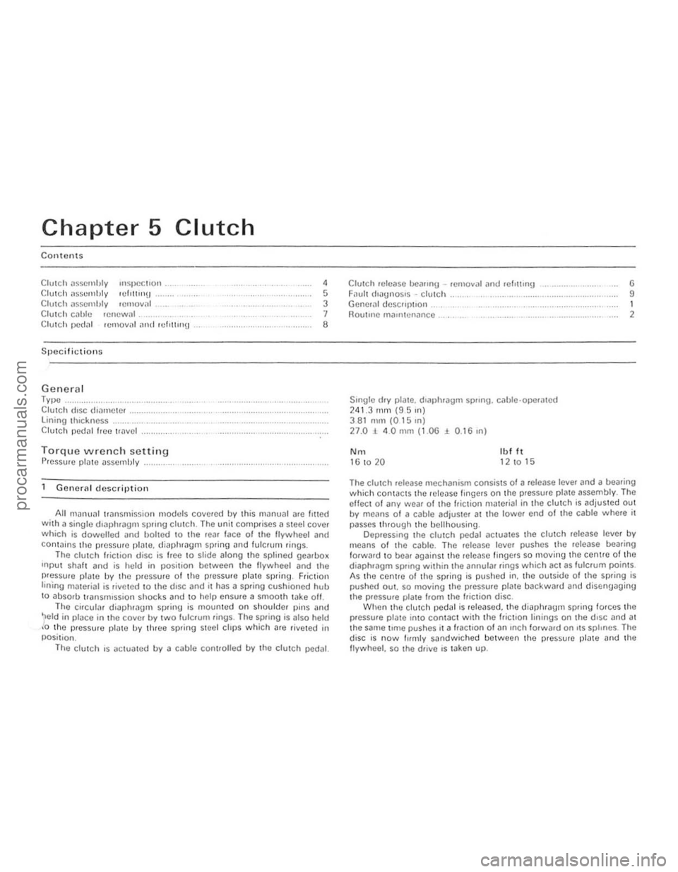
Chapter 5
Contents
CIUICh il$scmhty '"SIJoCcl'Qn . Clu\(;11 assembly 'Urn!!ll!) Clutch llsscmhly lemOY," C lutc h cilhle .efluwal._
Clutch
Clutch !Jedal rClllovnl illld ,cflltl"U
Specifictions
Genera l Type ..... Clutch (lise (hamClcr lining tlnckncss Clutch pedal hcc "
Gene.al description
,
5 3 1 8
All manu:!1 transmission madllis covered by this manual nrc lilted Wilh a singlo dl3phrilgll SpllJlg clutch. The unit COlllt)riscs il steel cover which is dowelled and bolted to the tear lace of the lIywheci ilnd conla i.lS the pressure plnte. diaphragm spring and fulCrum .ings . The clutc h " iClio n disc is
ee to slice along the splineJ gearllox
Inpu t Shillt and is held in posi t,on between the flywheel and the pressure plate by the pressure of the pressure plate spring , Friction linIng materiill is riveled 10 the d,sc and II has a spring cushioned hull to absorb transmission shocks and to help ensure a smoo th take oft. The circular diaphrilUm spring is mounted on shoulder pins ilnd
'Ield in place in the cover b.,. two fulcrum rings . The spring is also held ,0 th e pressure platc by three spling steel clips which are rive ted in
posi tion .
The
clu tC h ,s aCluated b.,. a cable controlled b.,. the clulCh pedal.
Clutch '0Ie,150 bCilfl"U -remova' and wl,u,"g Filult (ioilU"OS'S -clutch Generill descllptlon . noutlilc rn,untenanco .
SlIlgle (Iry plate. dlill)hragm sprong. cilhle ·ope.ated 241,3 rnm (95 Ill) 381 nun (0 15 In) 27.01 40mm (1.OG:i 0 .16,n)
No. Ib l It 16 to 20 12 10 15
G 9 1 2
The clutch release mechanism consists 01 a .elease leve. and a bearing which conwcts the lelease Imgers on the pressure plilte assembl.,.. The eHect of an.,. wear of the friction ma terial in the clutch is adjuSled out b.,. means 01 a cable adjuster at the lowel end 01 the cable where it
passes through the bell housing .
Dep.ess lng the clutch pedal actuates the clutch release leve. b.,. means of the cable . The lelease level pushes the lelease bearing
forward to bear against thO release l ingels so moving the centre of the diaphf()gm sprong within the annular rings which act as fulcrum points.
A s th e centrO of thO spring is pushed in. the outside of the Spling is pushed OUI. so Illoving Ihe pressure plme backward and disengaging the p.essu.e plate flom the /tielion disc . When the Clutch pedJI is Icleased. the diaptllaglll spring torces the plessule plate into contac t w ith the frictIon linings on the d,sc and at the saIne t,me pushes it a flactlon 01 an InCh fOlward on I\S splines . The
disc is now fuml.,. sandwic h ed between the plcsswe plnte Dnd the
flywheel. so the d.ive IS laken up.
procarmanuals.com
Page 129 of 205

)
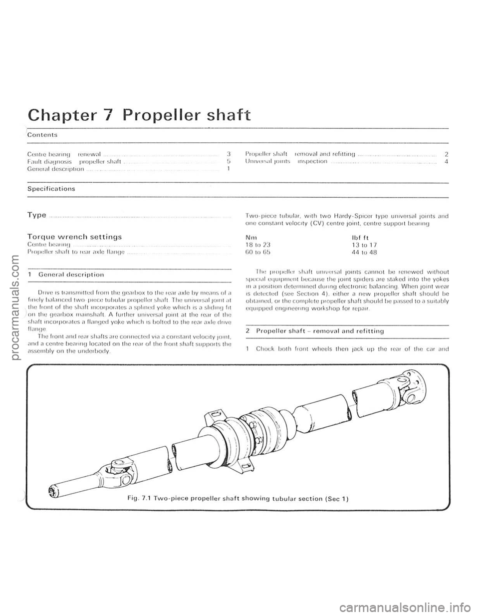
Chapter 7 Propeller shaft
Contents
Cenl,C be"wl(J rCl1<,w,,1 !':HlII d'''!I(lOSIS 1',01'"11,,, Shill, Gel,..,,;!1 li('SCIIIIIIO"
Specifications
Type
Torque wrench settings C{:II(,,, I,/!,,, ,,,! )
(',op"lll:r shall (" "',II i,xlc I I,moO]
Cello!',,1 duscriptioll
3 , ..
o"V() IS lI"Il~""w,d 110m III!: HP.;uh<)x 10 thCIVill ,"xlc hy mpdns "r " r",,!ly 1)"I,lIlted two 1''',Co) tuhul;1I p,opcli.:r ~hafl The u 'Hv""Si,1 JOlin ;" 1he 1'0111 of tile ,hilh IIH:()rpOI,lICS;) sphno"r yoke winch IS,' ~hd"'!II'1 Oil Iliu \lUilllJu x "''''''SIHlft A (w Illel lIIuvcrs"r lUll)! ,11 11'0 leill uf the f.Il,1f1 IIl(;orpOr;\I(!s iI [lill1lter! yoke which IS holled to the Ie", ,1xle drive !lilll\IC The honl ,111<1 "."" sh"hs illU cOIll"'cl(,d vIa a COI1~1
!'wpldlc, ~h;!h ,ctl1()v;)1 ,md rcf,UIIlU l)n,v,,,,,,II'''''IS '""pectln!) 2 .,
TWO'IHCCll tl1l>\lI., •. w llh lwo HMdy,Splcer type uillvelsitl 10lols an d 01'(' COIISWII1 V"loc,ly (CV) ccnl.e 10"'1. CC"lIC SUppO' 1 IUI;II">!)
NIIl 1 B 10 23 (;0 hI tj~
'1)111 13 10 17 114 10 48
II", 1110) ",11." ,hol!1 ,,,uv,,,s;r ) )OUlls C;IP"lOl hc ICllewed wllhoul ,purloll "'l"'Pllh:ll1 hcciI",e Ihe )01111 s pldels ;IIC sl"ke(1 11110 Ihe yokes ,n i> I'OSl1l011 dUWln)lnud dUlln9 elccl ,olHC h;>l;lI1cin\j When 101111 we;u IS dd,'Cit,d (seu SectIon 11). "ilher .1 new IHopelh;. sh~1t should he ohl;"""d. 01 lilt) cOlllpl{,tc plopelle. shah shQuld he p;rss~d to;> SIIII.IUly
equI pped el1!).necIIt>\j wOlkshop lor I~pn"
2 Propeller sh
ig. 7. 1 Two-piece propeller shaft showing tubular section (Sec 1)
procarmanuals.com
Page 133 of 205

Chapter 8 Rear axle
Contents
Axle rear cover .. lemoval and .etliling Axlosha!! bearing -renewal Adcshah -removal and refltllng . Fnul1 diilgllosis -re3. ,1xle Gcncr
Gel \cra' Axle dcsI\)n
Torqu e w re nch settings Bc,uinu (31) \0 axle Cilsing Cover \0 axle caSing CrOWllwheel Axlcshalt bearmg retainer /backplate . Drove pinion nut ....... ....... .. Rear 51),ing U·boh Stabilise. bar clamp boll _. Propeller shnfl 10 lear
6 !i ,
11 1 10
The rear axle IS of the hypol(f seml·floallnO tYI)oO and is located hy semi·elliptic ro~d springs, In conjunction with a smhlliser har. The dilJerel11inl is intogral Wllh the axle hOUSing and Ihe rear axlo
InuSt he removed to carry out ilny rePil" S to the dll1erellt,,,, wh,ch milY hecorne necessary . J The drive pinion runs in two lapered roller UeiltlllgS, which are "reloaded by a spacer . Early a.l"s have a ',xed lengltl Slh'lcer and I
PUlIon 0.1 so,, , renew"l . fie;]! .1x10 ove.h;wl Ilear axle ,emOYil. and refIlling f1ollll!w 1ll00intCIHlIlCC • Wheel siud renewal,"
() (Sahshury)
7 8 3 2 ,
Ilypo,d. sem,·flo,lIU1!), onteorill dolle/ent",', limited-slip dollelenl,')1 on 28 Speciill 300.1
I I loire (1.0 l)il11) SAE 90 015 mill (0006 'n) 2510 2 7 N,,, (I 8 to 2.0 IIlI tt) 010 to 020 ,nm (0004 to 0008 in)
Nm 60 10 68 35 to 45 801087 27 10 31 100tol20 25 to 36 401050 60 to 65
Ibl It 44 to 50
26 1033 501064 20 to 23 74 to 89 18 to 27 301037 44 10 48
obwined by Ihe use of selected shims inserted belween Ihe pin ion and rear t
procarmanuals.com
Page 136 of 205

m
)
Chapter 8 Rear axle 135
Fig 8 .8 Drilling the beMing rf!t
5 AxlcshiJft homing -renewal
Noto: A SfJL'CI.1f 1001 IS "Hlliller! /0 n'III1:''''''[1 (,0111 lilt' axles/mIl (s,:c Fly 89) 1 Remove the ;,xlushalt as ,h:sG"hcd 1(' St;CIl0n 1 2 Usin\J all 8 mill (0.31 In) dldl, 1Il;,kc a hole III the he,Hlnt! ,etauun\1 119 . t
G Cleiln the l1xlcshnf1. be,non\) ,,,t;WlC' ,Hld "xle C.,1511l\) 7 Locl1le the loe1ll1ll9 HIWlIlel 011 the l1xleshl1lt. followed uy tho new uoa,ing wIth the 001 sel1l [l1CIll\) l1WilY ['om the l1~leshaft Hallge. 8 Slide on the new hea'lIl\) rcta"lIn\) '1119 and pr ess J fully 11\l111l1st tile hearing inner IWck. uSIng a slJItJIJle puller or J ICWlth oftuue. 9 Re fIt Ihe l1xleshalt wllh refe'ence to S ectIon <1
6 Axle reM cover relllov,,1 ilnd refitting
Chock the hont wheels then lilck up the re,l( o f the Cl1r il'l(l SOPPOI1 on axle stands.
2 Cl em1 the reM cover .Jnd surroundIng .Jre" (photo) 3 Remove the hllmlbr"ke relay le ver lind seco nd.Jry cable. or
transverse ,od (as ;;Jpplicilblc) with reletCnce to Ch"pter 9. <1 Place a suitable container helle~th the reM "x Ie to c~tch the oil as the rear cover is removed.
5 Undo and remove t he ten IJOlt s and sprinU washers lhilt securo the reill cover to the llIl,l l drive housillg LIlt aWilY th e re"r cover and its
\Jasko!. ~ Before refitting the ,oar cover Illilke sure thm the mating fJces ilre free of th() old Uaskct or 10nlting compound.
7 FIt a new uasket Jnd then the lea, cover and secure wIth the ten bolts and spring washers. The cover bolts protrude IntO the fillal drive hOUSor1U so it is important that a SUlwble oll·resist.Jr1t scaling
... __ ro*
Fig. 8.9 Usill(J the special Ford tool to removc the axlesllilfl henring (Sec 5)
r;olllpoulid IS SlIll:ilr() d onto lioe Ihro,'ds of each boll bef ore it IS [,twd. 8 TIUhwll tllr: cover secu,,"!.! holls 10 lhe spec,[,ed torque Wfl:IICh
se ttln\)
9 ReCOlillect
Iht! h,lndbr,l~e components with re ference to ChJp ter 9. 10 R efil l ti,e 1e;1I ,ule with the correct 9rJde 01 oil then lower the C,lr to
the UIOUIl(i
G
2 Axle reM cover
7
Pinion oil seal -re"cw,,1
This ope r,ltion may be performed WIth the rear axle in position or on
the benc h
2 Undo ~nd remove the two holts. sprinU Jlld plain washers that secure lhe centre bearing support to the under51(fe of the body (reler to
Chapter 7) 3 With a sc"ber 0' fde. Ill
propeller sha h to ttt() flool I I
J m
procarmanuals.com
Page 140 of 205

•
Chapter 8 Rear axle 139
ci,cumS«"Ulces mny only one pmt of the two be renewed. fnspect the dllfe,enti,ll pinions nnd side gems for signs of pitting. score mMks. Chipping nnd general wem. Obtain new gears as necessa,y . Inspect the th,ust washers lor signs of weM or deep sco,ing. Obwin new thrust wnshe,s as necessary. Once the pinion o il senl has been disturbed it must be discMded and a new one obtained. 20 When new pnrts have been obwined ns required. reassembly cnn begin. First lit the thrust washers to the side gems and place them in position in the differential housing. The ground side of the thrust washers IllUSt lace the side gC.Jrs. 21 Place tile thrust wilshers behind the dillelentini pinion genrs i1nd mesh these twO Oems with the Side gears through the tWI) ilpertores in the lilllerentlill housing. Milke sure they ilre diametlicilily opposite 10 each other. RO«l!e the clillerent'i11 pinion gears through 90' so brinUlI1\j them into line with the pinion genr shnlt bore 111 the housinlt 22 Insert the pinion genr shnft with the lock In!) p'n hole III line with the pill hole. 23 Usinu leeler 1),IU!Jcs. measure the en{lll(",t 01 ench s,de Be,,,. II the speclficd h\Jure IS excecrt"d. IU!W tl"u~t washlllS mu"t he olJt,uned
-omnlllie the a~~el)lhly ,lg,llll ,trld ht new thll,st wa:,lu'
28 Using soitable diameter tubes. fit the two Wper roller bearing cones into the finnl dlive housing. making sure that they ale litted the correct way round. 29 Slide the shim and spncer onlO the pinion shalt and insert inlo t he final drive housing. 30 Relit the second and smaller diameter wper loller bea,ino onto the end of the pinion shaft lind 101i0w Ihis Wilh a new oil seal. Sefore Ihe senl is nctually fitted. apply some grense to the inner Ince between the two lips of the seal. 31 Apply n little jOinting compoond to the outer Ince of the seD I. 32 Using n tuhulilr dllft 01 suitable dinmeter, carefully drive the oil seal into the fillal (hive housinlJ. Make quite sore thnt it is lilted squarely and flush with the housinU. 33 Refn the drive pinion IInnge nnd hold securely in n bench vice. It II fixed lenIJth spncCl is Itlted. fit ilnd tighten the pinion nut 10 the spec ,lied lorque. If a collapsihle spnce r is f,tte d. follow the prOCedlHe
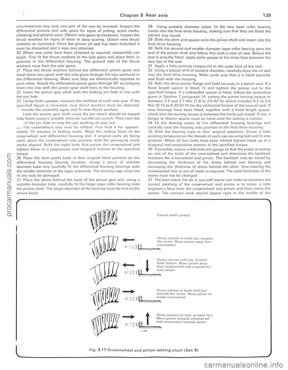
g iven in Section 7 paragraph 14. setting the pinion turning to'que to hetween 25 nnd 2.7 Nnt (1.810 2 0 Ihf It) which includes 0.2 to 0.<1 Nm (0.15 10 0.30 Ibl It) lor the ndriitional friction of the new oil senl II new hea,inns h~ve heen filted. logether With n li~e(l len(Jth SP,lCer. check thm the tOrlllllg torque is bel ween the limits just stmed. If not. a longer or shorter spilcer must he I,tted until the setting IS correct 34 Fit the healing cones to the cf,fierenllal houslIlg heallll(Js and carefully ease the housing Into posilion in the finill drive housmg 35 Relit the be,IIII'!J CilpS in thell originnl pOSitions. Srnc,ll n httle JOlntmg compound on the threilcfs 01 each cnp secuIII'O bolt nnd fit 11110 position. When ,111 low halts have bcen rein ted tiUhten these up in a (h"IJonal and progresSive milnne, to the speCi fied torque. 36 I I pOSSIble. 1Il00nt n dlnl in(licntor onu(Je so thnt the probe IS resting on one of the teeth of the crownwheel and determine the backlash hetween the clownwheel and pillion. The bileklash may be vMicd by elecreasll'\) the thickness of the shims bellind one beilling nnd incrensing the thickness of shirns behind the othcr. thus moving the crownwheel ;nlO or out ofmcsh as requi,ed. The tOt.llthlckness 01 the shims must not be chnn\)ed. 37 The hesl check the do·it·yourself owner cnn make to aSCerta", the correct meshinu of the crownwheel ilnd pinion is to smear ,I htt le engineer's blue onto the crownwheel and pinion iJnd then lot"te the pinion. The con1
_
t Heavy conWCl 0" huel. at 100lh !,leu Move p'",on lowa,ds crownwhcd u:.!:.crt:1 3nd c,ownwhuel towards p,n,on
.~\;!~" •. ,;.';,;,"",.,=,"--
l ' Fig. 8.17 CrownwheeJ and pinion setting chart (Sec 8)
, ,
, ,
"
procarmanuals.com
Page 142 of 205

Chapter 8 Rear axle 141
lings apm! and compress the clutch plntes. The nction is varinble. depending on the power npplied. so tlMt under full power the dIfferential will lock completely nlld full torque will be appl;ed to both
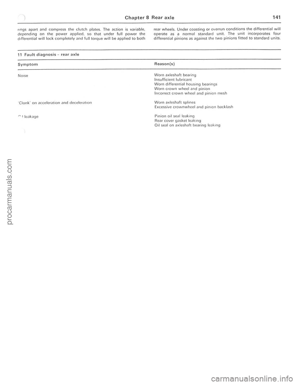
11 Fa ult diagnosis -rear axlo
Symptom
NOIse
"Clonk· Oil nccelera tlon nnd deceh:ontlun
,... Ilenka\Je
)
renr wheels . Under coasting or overrun conditions the differential will operate as a normal stnndard unit. The unit incorpora tes four different;nl pinions
Worn axleshaft bearing Insufficient luhricant
Worn dlfferentinl houSIng bearings Worn crown wheel and pinion Incorrect crown wheel nnd pinion mush
Worn 1I. leshalt splrnes Excessive crownwheel nluJ pinIon bncklnsh
Pm ion oil senl Icnkrng ReM cove r gasket leaklllg 011 seal on
procarmanuals.com