1974 FORD CAPRI wheel torque
[x] Cancel search: wheel torquePage 143 of 205

Chapter 9 Braking system
Fault rflnunosis -hrnking sys tem Foothrnk.c I)(!dnl -removal .1nd refluing From m ake caliper -overhau l .. Front blake cillipCf -removal ;1nd 'Cl,UUl\1 .... ______ ._ .................... . Front brake discs -inspection, ,enlov,,1 and rcl,!\in(J Front disc pilds -renewal , ....... _ ...... .. General description ..... .... ........ . ............ . H andb
Syste m type
I=rOl1t brakes ~c tt,ickncss :
Now ....................................... .
Min rmum.
Oisc fun ·out (ma~inlum including hub).
Mini'l1ulll disc pad lining Ihickness
Re ar brakes MInimum bfake shoe lining thickness.
Torque w re nch settings Caliper ....... ................. ................................... . Brake disc .................... . Backpl"te ........................... .................... .......... ................ .... .. .. .......... . Hydraulic unions. Bleed screw (ma~) .... Aecuf>Cfaling valve 'Clainel (Gi,ling)
Gonoral description
23
16
5 ,
G 3 1 18 20 19 14 15
Oisc brakes aro f;tted 10 Iho front wheels and drum brakes to the lea. wheels. Tho cable or cablo and rod opelilled handbrake oper:11es independently on the real wheels. A vacuum sorvo unit is fiued
" "tween the mastel cytinde. and loolbrake pedal to provide assistance 'en the pedal is depressed.
T he hy,aulic circui t is split frOnt and rear. Undel normal conditions
M,lSIC' cylinder -ove.hilul Milsle. cylinder -removill ilnd .e liuing . P.eSStue d,ffcrenliill swit c h -desoiplion .• e m ov,,1 and .el,ning P,essure ,educing valve · description. relllovill ilnd .er,llonu
Reil' i),lGkplilte · ,emov"r ilnu refining Hei!( i)r"ke shoes -renewal ....... .................. .............. . . Routine m"intenance ........ . ................. .
SlOp·lilmp switch - removal. re/rUlng and ildJustmcflI . Vilcuum servo unil _ description . Vncuum servo unil -rcrnovnl nod rcfiUing Wheel cylindcr -rcmovnl. ove.haul and ref'lIing
11 10 12 13 ,
7 2 17 21 22 8
Dlml hyd'i1ulic cif cuit. snlol Ironl i1nd rCilr WIth IlreSSU,e reducing v:llve in reil r ci.cui t on Iiller models. DISC I,onl brilkes i1nd self·ndjust illu rca .
(!rum brilkes. all wilh servo aSSIstance. Calrle or c.,blc .1nd rod operated handbrake on rear l)f"k es
12 .7 mm (0.5 in) 11.4 rnm (0.45 in) 009 nlln (0.0035 in) 3 .0 mm (0.118 in)
1.5 mm (0.059 in)
Nm 471068 41 1046 271031 71010 10 491062
Ibl It 351050 301034 20 to 23 5 to 7 7 36 to 46
both ci.cuilS operale in unison. howeve •. in the event of faIlure o f one circui t Ihe lemaining ci.cui l will p
Page 146 of 205
) Chapter 9 Braking system 145
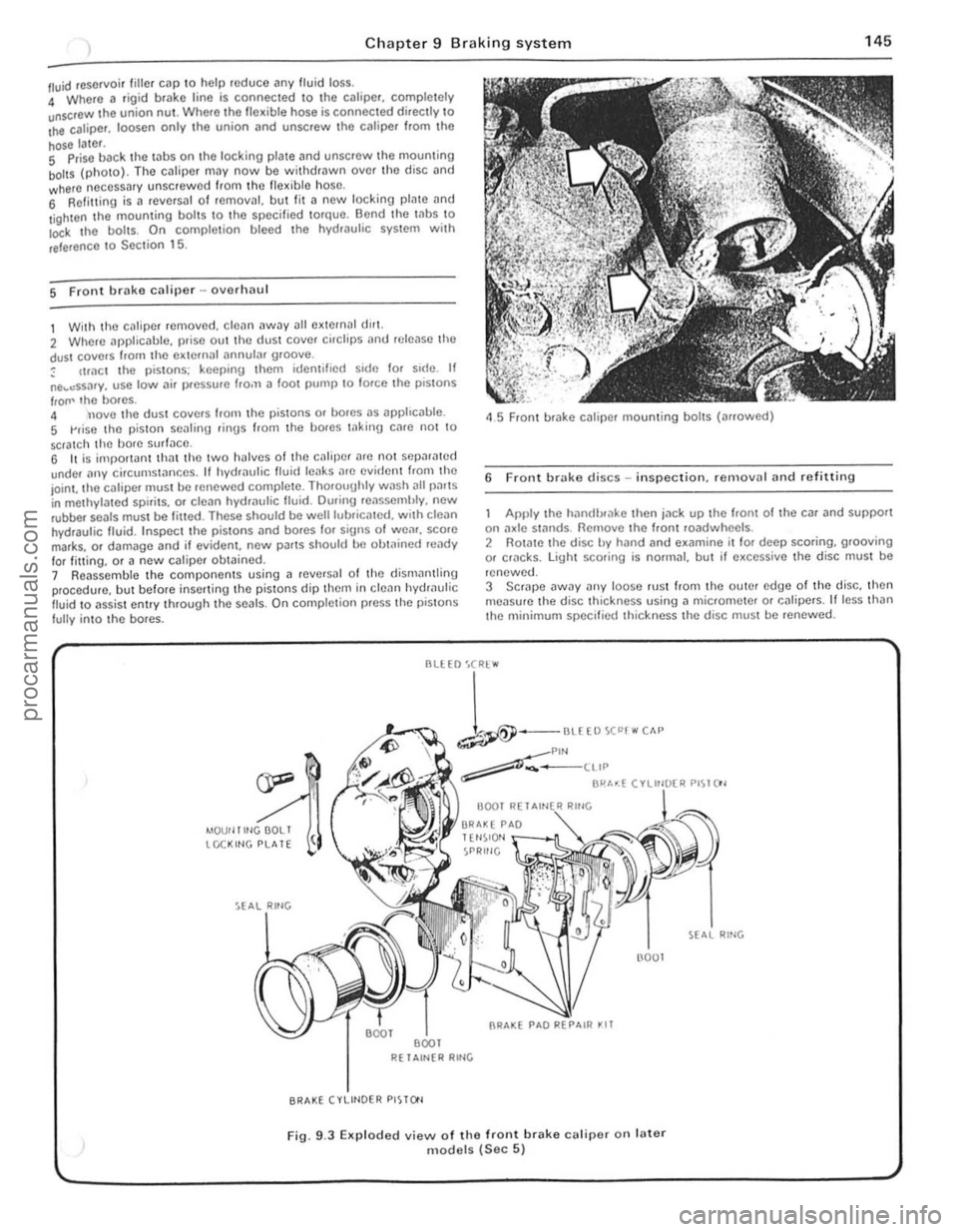
/ll.Iid reservoir tille , cap \0 help roduce any fluid loss. 4 Where a rigi d brake line is connec ted \0 the calipe r, comple tely unscrOw the union nUl . Where Iho flex ible hose is connected directly \0 Ihe caliper. loosen only .he union (lnd unscrew Ihc caliper f.om Ihe
hose later. S Prise back the laus on the locking plale and unscrew Ihe mouming boilS (photo). The cJliper may now be wit hdrawn ove r th o disc and where neCessary unscrew ed from Ihc flex ible hose, 6 Refilling is a revCfsal of fernOv;!I, but lit a new locking plate and
l ighten the mouming bol ts \0 the specified torque. Bend the Inbs \0 Io<:k I he boils. On comple tion bleed the hydwulic system wit h
reference \ 0 Sec tion 15.
5 Front brake caliper -ovorlulU l
1 With the c~liper removed . cle~n away all external dlr1. 2 Where applicable, prise out the dust cover cirClips
IrOIl' lho bores. 4 nove tho dust covers Irom the pistons or bores as apphc
45 Front brake caliper mounting bolts (arrowed)
6 Front brake discs -in spection. re rnovnl and refitting
Apply the hilndlxake then jn ck up the hom of the car and support on :1xle st:1flds. Remove the Iront roadwheels . 2 Rotate the disc by hand and examine il lor deep scoring, grooving or cf1lcks. light scoring is normal, but if excessive the disc must be
renewed.
3 SCrJpe
--
1-""£0""""" ~Plf'l ~-____ ttIP
BI"'~( ".",~"" PI~I()'
4IOUf llltlGOOLI tCCKltlG PLATE
R( 1 Altl{R RltlG
BRAKE (VLIHOER PISTO'l
(l001
Fig. 9.3 EKp loded view of the front brake calipe( on fater models (Sec 5)
RING
., .,
,
procarmanuals.com
Page 147 of 205
Chapter 9 Braking system
4 Note that in order to m,lintOIll even braking both discs should he renewed ill the sal1 1 e lime
5 T o remove il dl~c. first remove the tHlb as described in Chllpter 10 . 6 Prise lip th(J locklllU I"hs. unscrew the fOlll bolts. and remove the disc from Ihe huh.
7 Clcilll the Illllirnu !ilces of the disc and hub then locale the diSC on the huh and allgel the holt holes.
8 InScrt new holt~. tOI){)ther w rth new locking plates. and tiuhten them to the specrfre(1 torque_ loc k b y bending the tabs. 9 Th e huh Illily now he ref Illed with reference to Chapter 10.
7 ReM hrake shoes -rt)rlewal
Check the front wheels th!:n lilck up the rem of the CM lind support on ,1~le stands. Rel(,a5e Ihe handbr,lke lind femove the reM roadwh~~els
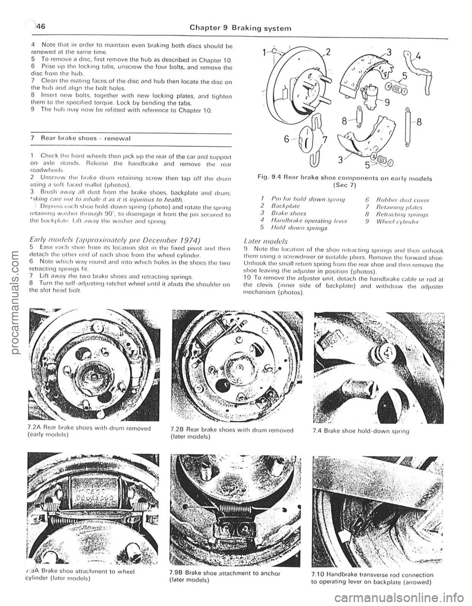
2 Unsr",w th" I"ake drum lewinrnu scrow then t.1p off the ,IIurn \Jsing ;I ~"It f.lced milliet (photos) 3 Barsh away all dust I.orll the brilke shoos, backplate ilnd drum, ",killfl can' ""I /0 11111""., II ;I S 1/ is iHjmiaus to "e,11Ih Del""~~ ,,;och shoe hold-down sprrng (photo) ,lnt! rOt,lte the sprrn!! ",w"nIlH w.r~I"" th,ou!lh 90" , to rhsengage ,t from the pm sel:rr",d 10 Ihe had' pt. 'I" 1.,11 ,"wily 1Ill! w;'shel and spm}!J
Early moth'ls (iippmxilllawly pm Df!c()tllbcf 1974) 5 Eas,) .. ad} shoe loom ,t~ loc;rllol1 slor III the lixed pivot nrrd tllen detach th,-othe! '~nd 01 ea(.11 shoe f,om the wheel cylind'lr, 6 Note whld, W.1Y fOwul and IIltO which holus in the s hoes tlH~ two retracting sP""Hs Ill. 7 lift ,lway t ho two brake shoes "nd retracting springs. 8 TUf(lthe self- ad lust'ng ratchot wheetum,1 it alJuts the shoulder on t he s lot head bolt.
FiO_ 9.4 Renr brake shoo components Oil e,lrly moclnfs (Sec 7 )
I Pili 'm froft! dowII sWIIIII 2 Buc/."liTlt! J B',l~'l! shot's <1 II,-IIIrflHiiAe opcra/jllY h-v", 5 lIo/d d"wII slNil/ys
Lawf lII oduls
6 fir"",,:, (/",,1 r:lJvlH 7 IId;III1I1'!IIII.llr!S 8 flNr;Il:IIl'!! .,'I,"IIIIS 9 WI",,:II:yllJldl!l
fJ N Ole the local,on of the shoe 1"lpacl,no sprrll!ls nrld thell unllook tlwm \lSUl!l a s(;lewrh,vef or SUil;!tJle plo~"s. Remuv,) th" lorw,lrd shoe Unhuok tho small pelurn spring loom the reill shoe and then rumuve the shoe lenvinlJ the adJus!Cr in pos,tiol} (ph o tos)_ 10 Tu remove tim adjuster unit. del
,
j
procarmanuals.com
Page 159 of 205
)8 Chapter 10 Suspension and steering
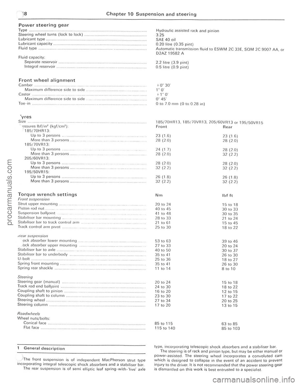
Power steerin g gear Type .. Steer ing wheel turns (lock to lock) lubrican t Iype, Lubricant capacity . Fluid Iype .
Fluid cilpacily: Sepilrilte reservoir . Integli!1 reservoir .
Front wheel alignment C",nbc, M;lXll11um dlffcrence side \0 side C
195/50VR15: Up 10 3 pe.sons . Morc th(ln 3 persons.
Torque wrench settings Fran! SIIS{!cl!siotJ Stlut upper 1110untrng . P,ston rod nut Suspen Sion ')~",{Jont St;rhiliscr birr mount"'lt . Stab iliser h;rr to track control ,)In,
Track cOIHlol ~rrn p,vot
,H'o1( slIspCIlsion od abso,bcr lower mountH'g .ock absorber upper mounting Stabillser bar to axle .. St;rl.lIlIscr har 10 underbody
U ·bol . Sprinu I.ont mount"'g . Spring rear sh;rckle
SINNing Steering gear (m~nual) Track rod end uall,oint Coupling shaft to pinion. Coupling shah t o column . Steering wheel.
Steering column.
Roa(/wiJec/s Wheel nuts/holts: Conicall;rce . FI(lt face.
General description
, -'The flonl suspension is of Independen t MacPherson Strut Iype incorpotating inleglal telescopic shock ~bsorbers and a stabilisel b~r. The ,eal suspens ion is o f semi ellip tic leaf spring·with· 'l ive ' axle Hydrau
l
ic assisted rack tlnd pinion 3.25 SAE 40 oil 0.20 litre (0.35 pint) AulOm
1- 0 ' 30' I" O· I l' O' O ' 45' 01070 nun (0 !O 0 28 ",)
185170HR13. 185/70VRI3. 205/60VR13 o. 195f50VR15 Front Rear
23(1.6) 23 (1 6) 28 (20) 28 (20)
2<1 (1 7) 28 (2.0) 28 (20) 32 (22)
28 (20) 28 (2.0) 32 (22) 32 (22)
26 (1 8) 26 (1.8) 32 (2 2)
32 (22)
N'H Ibl It
20 to 2<1 151018 40 to 45
30 to 33 <11 to <18 30 to 35
28 to 33 21 to 211 21 to 61 15 to <15 25 to 30 18 to 22
53 to 63 39 to 11 13 27 to 33 20 to 2<1 40 to 50 301037 35 to 41 26 to 30 25 to 36 181027 35 to <11 26 to 30 11 to 14 8 to 10
20 to 24 15 to 18 24 to 30 18 to 22 16 to 20
12 to 15 231030 17 to 22 27 to 34 20 to 25 17 to 20 13 to 15
85 to 115 63 to 85
115 to 140 85 to 103
type, incorporating telescopic shock absorbers and ;l stabdiser bill. The steering is of rack and pinion type, but may be either m(lnual or power·assisted . The steering wheel incorporates 11 convoluted cam which is designed to collapse rn the event 01 (In accident to prevent
injur y to Ihe driver. It is not reco mmended that the power steering gear is dismantled on Ihis work is best entrusted to a specialist.
procarmanuals.com
Page 165 of 205
Chapter 10 Suspension and steering
~ l"Nfl> BUS"'''G
~ TRACK CONT~O~ AIIM
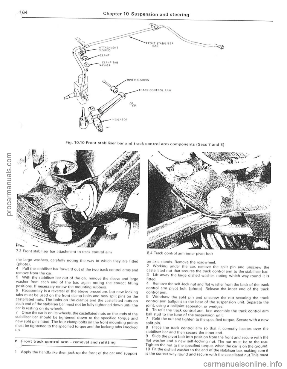
Fig. 10. 10 FrOllt st
Front Slilblliser bJr iltlilchmCIll to tr
5 With the stilbiliscr bilr out of tire Cilr. rernovtl the sltltlve Jlld lilrge wnsher from each end 01 the bar.
7 Once the car is on its wheels. the c(lsteli,lted nUlS on Ihe ends olthe st,)bifiser bar should be tl\[htened down to the specIfIed torqlJe .. nd new spill pinS filled The four cl(lmp bOilS on the IranI mountinu poinlS must he tluhtened 10 the specliled torque and tile lockIng whs knocked up.
P
Front truck conlro l ;lrm -removal alld refitting .
Apply the h'lIldl.>r
on a~le swnds. Remove the roadwheel. 2 Working ullde! the C(lr. remove the spirt pin (lnd unscrew Ihe cilslellmed 11111 Ih"t secures the trilck coniroi
5 WithdrJw the split pin [lnd Ullscrew the nut securing the trilck control Jflll battlOIl1 10 the base 01 the suspension unit. SCpar[lte the joint. using n ball,oinl Sepnr[llo,. or wed(Jcs 6 To ret, I thc lI"ck conlrol arm . fllsl JsscOlble the track conlrol [lrm bJIl stud to Ih(~ bilse of the suspenSIon !m't 7 Reflllhe nu! ilnd tighten to the speCIfIed torque. Secure with a new spirt pin.
S Place the track control (lrill so IhJt il conectly locates over the sliIbiliser hJr nltd then secure the iIlller end.
9 Slide Ihe pivot bolt into pOSItion "0111 the "onl and sccure w ith Ihe flat washer Dud il new scll.lock,no nut. The nut must be to the rear . Trghten the nUl to Ihe specified torque. when thu car is on the ground. to Fit the dished washer to the end of the stabll iscr bDr. making sure it is the cOllect way round and secure wit h the cas tellated nut This must
-------------------------.. procarmanuals.com
Page 166 of 205
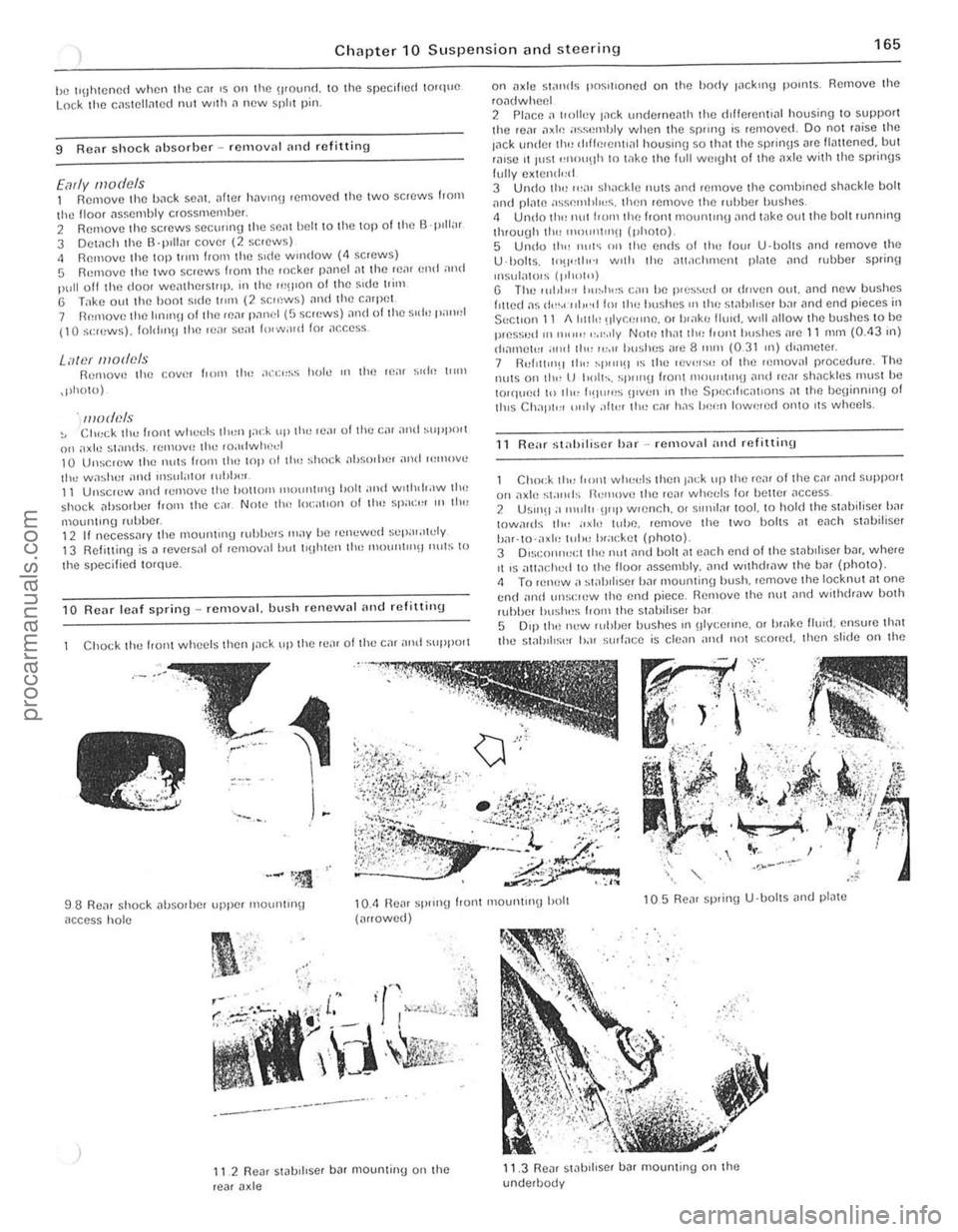
Chapter 10 Suspensio n and ste e ring 165
he IllJhlCned when Ihe em IS on Ihe '1IOUI1(1. \0 Ihe speclhe(1 100quO Lock Iho cnSlC\lnlCd I1UI wllh n new spill pin.
9 Renr shock nbsorbcr -rClllovnl nlld rofitting
Early models 1 Remove Ihe bnck sent.
.pholo)
. models ~, CIlr:ck the front wheds Ihun F":k up th,) rca r olthc (:;" and SUPI"lI l on "xle swnds. tCmovH Ihe ,o.ldwlwel 10 Unsc,ew Ihe nu(S Iron' tim lOp 01 III" ~hock ilhsnrhe, ilnd ,,:move the wa~her and ,nsul"l!)r rllhh,,,. 11 Unscrew nllll ,emove Ihe hollom IIH)l1ll1l"~1 holl and wllhd,.lW Ih(, shock nhsOliJer trom the cnr. Now tlw 100:"t,on of Ihe Sllacr:, '" II",
1110ul1lll1g lubber. 12 If nocessmy (he moun(lng lUhbers IIlay be relwwed sepal;l1cly 13 Relittinu is il reversal of refllov
C
hock I hl) hOI1l whl)l)ls then Inck up Ihe rl);11 of Ihe cm nntl SliPPOlt
98 Renr shock ilhSOlbel upper mOIJnlln\j
nccess hol e
"
-----------_.-
II 2 Re~, stabi llser b ar mountinu on Ihe rear a xle
on
U ·lJol ls. 10'1",1"., WIth Ihe all.lchment pl,110 ilnd fubber splinf)
Insulatols (1,1",11') U The I(lhll'" Ilu~h"s C;\l1 be p,es'>vd 01 dl1ven oul. lind new bushes fllted ns {I",.( ·"l,,·d 11)1 Ih" hushes OIl Ihl! s!ahd ,se r bnr lind end pieces in
SectIon 11 1I1r1l1t~ !lIY CI;"nc. or I,,"kr, flUId . WIll
R eM st"hiliscr har -rcmovnl ,,"d refitting
Chock tlr" from WIH't:I~ Ihen Jack up (h o ron, 01 the cal ~nd ~Hpport 011 nxle stands il"I1love Iho rear whet:ls fo, holtcr ilCCeS$ 2 USlnO :1 11111111 !J"P wlCnch. 0' sll1>llnr tool. to hold the swoiliser b,'r IOwa,ds 11r"
5 0'$1 Ih(~ new ruhber bushes III olycelll1e. 01 hrake lIuld. ensure that tho stabIlise, b.H ~(JIlnce is clc
procarmanuals.com
Page 167 of 205

,6 Chapter 10 Suspension and steering
A
l
I Lr;=::;;r""~Jj'Q l
G-cc;;;;-~---~~~~~
, " I : I 'II
'I' , ,
, ,
FiU · 10.11 Fl(Wr stniJiliscr b;H flnd piece positioning (Sec 11)
A IJ 2620 I J!J 111111 (/03 101m) 100111111 (0·1 mJ
1"'5 ;",(1 ,0.:1'1 tile t;1\{1 sHoec When l ilted. the wHip'cec should he 1'''~'ll'''H,,1 .15 shown III FlO 1011 DIIIlCIlS'Oll A should he betweell ?!.i 59 nlld 2Gtl 5 ""ll (102 ami 104 JI') :lnd Ih" (h(fmcncc IWlwr!f!1l IllI! two s"I"5 IIll1S! nOI he \l'catc, th.1rl 2 5 nUll (0 1 m)
(l II Ihe IJl,~hcs "' II", (,11(1 11".:';'$ "''1''''<) """,wi,I, II 'llaV I", found "'O'e COI1V"Il
h",,/.ul1,11 h.'vel (the wUIOht ",qlllred IS dpp'ox,m
J.!Ck lip the front 0 1 thn C,lr and place s1
2 Remove tile nul ~lId holt from the elnmp at the front of tile fleXIble COllpll ll(1 on the steerm!j colllllln, Tills cl,IInp hOlds the couplln(J to the pillion splines.
3 Working on the front crossmemlier, knock hilek the lockmg wbs orl the two bolts on each IJck houslllg U ·C lillllp. undo the bolt ~nd remove tbe locking tabs ~nd clamps
4 Remove Ihe split pillS
Th iS cnn be done by ensuflng that the d,swnces hetween Ihp. ends oj bOlh trllek rods 1111(1 the Stec1inu geilr hOllslng on both sides ~re the same .
7 Place the stee"ng Uear in it s 10c
-,
Fig. 10,12 COfrect position o f stnhiliser bar ruhher bush {Sec11 )
T'!jht(:n the holts to Ihe speclf,(:{! to"lne, 9 Relit the I.,lck rod ends into the stO)(:IIn!) illluS. refIt (he I:a';[ellolted nllts and II!Jhten them to the slleclfl{)d tOlque Use new spill pillS to '!:t.nn the nuts
10 T'!lhten tho I:I,II"P bolt (HI the steeru'!J COItIllHI lIex'hle couphllU to 1f1n spec""~d torque. h,)vIlI!) fll~t rnil(\e SlJlOl tholt tlul pin lOll is cOlfecily 10(;"101(1 III t he S"III1CS 1 1 Lower the cm to tho urOllnd. thcn check nrld If neceSSo1ly ildJlIst the front whlwl ;III(J 'Hncnr 015 descrd)ed in Sec lion 20.
13 Stcerinu geM (Illanual) -overhaul <111(1 adjustment
Remove tlllltr ilc k rod nnds (Section 14) then .elllove 1)nd discard the Wile retalnlllg cliPS. remove the hellows and drall1 the I"hricant 2 Mount the stee"ng Ijear in
15 LubrientIJ the ball Seilts. balls and housings. with the specified gear 011 Screw the locknuts OntO the ends of the steeling (1)ck. 1 G Assemble t he sprlllgs. waShers. bJIl seJts. track rOd ends and housing. Tighten the hOllsmgs. to obwin a rowtionnltorque of 7 N m (5 Ibf It). then lock them w ith the locknuts. Recheck the torque alter tiuhtening the locknut 17 Drill new holes (even If the o ld holes Jre in aliunment). 4 mm {O, 16
______________________________ .1
procarmanuals.com
Page 169 of 205
)8 Ch apter 10 Suspensio n and steering
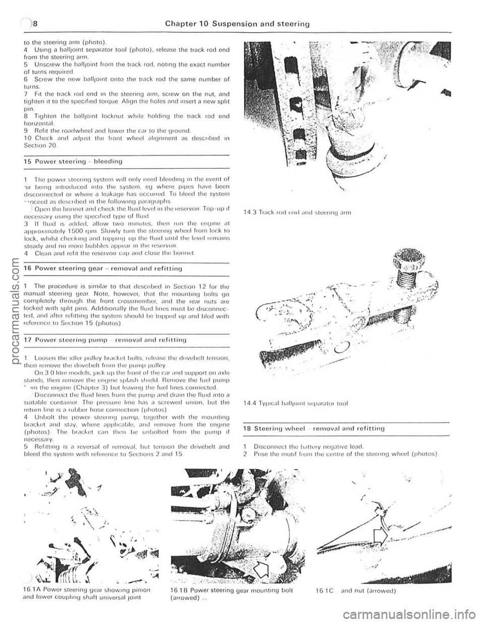
\0 the SI(lcring Mill (photo) 4 USlIlg" 1)[lIi)onH SCpilriltor tool (photo). reh:o,lS(l the ['ilek rod end from the Slc(!rino ""m 5 Unscrew the h,"'IOlilt hom the ['
The power ~1P.elln\J SysHllll WIll only need blc",rhnfj Ifl the even! of . .., hell1\J Il1tl<)(hu:ed ",to the system. cu whcn: IH llI:S h;IV() IW(}1l dlscoI1l1cc«:d or whel() J Ifl.lk"(Je has occlUfed To hleed the system ···ocp.ed ;'s (1<,~<:"I)Cd III 1(11) followlllU l),l';)\J,,1I)hs
I Open llH~ hO'Hl()1 ,111<1 cl\p.(:k the Il",d h:v el "llhe Il'Sl'IVi'" Top·llp.t llucess;IIY IIS"'!J (Il<) spe.:II,ed lype of 11(11<1 3 11 11."d IS added. allow two "'''HlWS. th"l1 lUll 11m I;I\U"W at apPI{)xIIllntnly 1500 rp'" Slowly \illll lhe st'!""Il(! wheel 1,0m lo,:k to lock. wlllisl r:l\.,,;klllH and WPP"'!I up Ih e Ihlld unlll th" l"v,,1 ",m;II11S
Stf),li1y ;1<\<1 no molC hubhl"s ilPP":U I II tlw I"S,,,V,,II
" elc ;,", and refn Ihe r"servoll cap ami close II,,, 1>0"",,1
16 Power steering gear rellloval and refittinu
The p'ocedure IS Sllml", to thilt descrd)<)d III Sc(:t lon 12 10' th" m,10u,,1 steeling gC,lf NOlO. how"ver. lhm tile 111011111(1)(1 1)I)Its (jo cOllipletely tl1(ouyh lhe front e,ossmflmhe,. "nd the II.),,, nil IS a,e
I()(;ked wllh sphl pillS. Add,llon"lly lhe lIuld IIIH)S rnu~;t Iw lhsc.onnec · l"d. and atln' ,uI,Um!J the system ~hollid he loppud III' ,lnd Illed wllh lui"",,,!:,, 10 $"(;tl{>n 15 (photos)
17 Power steerillU pump remov;ll "lid rcfil1 ill\J
Loo~"n tl", «II.." Iwlley 1",lck,,1 b"lts. ,el..,ase Ih" d"ve!Jclt lellSlon. Ihcn ,emOVe II", dllvelu:lt I,,)m the P"'''I' pulley Oil 3 0 101", IIIO
h,;lc.k(,t ~nd st;)y. wlw,e ;1j)1'11 <:;,I)I". ,!Ill! ","'ove f'DIII Ihe CII!) "le (photos). The "",d..,1 C;'rl lh"" 1m (lnl)nlt"d flOm Ihe pUlllp of nccess;"y, 5 RellltlllU IS .1 ,ev,,'~al 01 I..,moval. "ul l"'Il~lon Ihe lhlvehelt ~Ild "Iced Ihe sy~IC'" wllh lek'e'll:tJ to Sec;1I0ns 2 ,!Ild 15
"V',~, , .,' , -t .~/ ,.
~
' ---... . . ' .. ' , "
A-i·J<'~ r~ _ I' .' If! h \l:: fITI \~, . '''''
~
•• :. ' 10)",', / )
. .. 'I.· L../,
'": .. ':;' ., .... ---,.
. .. .
18 S teerinU wheel removnl nnd rIllittinu
1 Dlsconneci the lodlielY nCU~lIve le,,(1, 2 PIISC Ih" mOllf hUIll Ihe celn,,) o f Ihe stcclln(j whc,,1 (photos)
15.1 A Powef SICCIIIl(j (je,, ' showUlU pinlOrl and lowe, coupl",U ~h,,11 un,vcfsnl lo;nl 161 B Power steering ue", mountUlg bolt (,,"owed) 1 G 1 C "nd nul (""owed)
.' ---------------------------------procarmanuals.com