1974 FORD CAPRI wheel bolts
[x] Cancel search: wheel boltsPage 51 of 205

\.
50 C hapter 1 Engine
51 T llp pcts -removat
Remove the 1
5 2 Crnnksh
4 Wilhdraw Ih~ Wood'uH key hom the end of th(! CllInk5hah and pl,lC,(! " w'lh Ihe pulley. til(! holl alld its washer 5 The C'.1nk~h;)h p"lIey m;oy he ICliloved wilh Ihe eno,,,e III Ihe C:\I. hilt ,I 'S IIIsl tU!Ccss;o,y 10 ,emove Ihe ',ld'illO' :lI1d thc rh'vehelts
53 Flyw heel -remov[ll
P,even llhe flywhcel hum 101m",!) by FHlHllln\J Ihe lin!) !lcal ;ollain~1 ;In imp.ovised SIOI). 2 On nlodels willi nl;lnu:ol 1I;o"$""S5'01i. Icmove Ihe Clulch plessure 1)1;lle and disc :os described in Ch:op!Cr 5. 3 Rele.lse Ihe s,~ bolts secu.in!1 Ihe flywheel 10 Ihe CllInksh;oll .lnd lefl\OVC I,ve of Ihenl.
4 Whilc supporling Ihe tJywheel III pl;ll':e .• emove Ihc Sixlh hoi' ,'11d Iolt Ihe lIywheel otl c;o,elully. so 111:01 Ihe m;lllllg su.lilccs of flywheel [lild c.;onksh;oit ;o.e 1101 dllm,'ged
5 4 Sump -removal
W"h lhe '''1(1'''') oul fli the e,". CII~"'C Ihal Ihe sump has 1o('CIl d,amvd ;ond then lilln the engll1C ()VCI so tl1011 Ihe sump's U l)I)ClmOSI F" wOOr1CII bloc"s tn Slll)lmrl tim en!l'ne 'n Ih,s POSIIiOIl . 2 Remove 11m h()IIS seCUlln( J the oil Sump 10 Ihe CI.1nkColSe o1nd rClllOVO Ihe SUll1p_ 11 the sump IS stuck 10 the c r;ollkcasc . II should be reh;lIsctl hy 1"'SII1\1 olle SIde wllh 11 sClcw drover. 3 To !Cn,ovtl .Ile sump wllh Ihc CIIU"HJ Hl tloe eM. 11151 IcnlUVC Ihe
d'l)S llck :ond d'SCOIlII(!Ct Ihe hatlery 4 Remove Ihe luur holts ;ond lou. Ch,)S ;ond dCI.leh Ihe OIl splash
shIeld.
5 Pl;oce a Con'"lIlcr 01 at lellst 6lttre (106 JlIllI) cal,,-.elly heneath Ihe SUml). remove Ihe d,ain pl\l(l ;ond d,aln Iha sump. Reflilhe d.am plull and (11)hlen II 10 Ihe 10lqUO wrench seilIng gtven In the SIXlClflC;JIIons G Del:och the engme fubl)CI mounllngs, by lemovlng the" nuts an(1 w:oshe!s. 7 Romove the ciampinI) bolt hom the tal) ;oml bOIlOI11 endS 01 the Steellll!.) intellnediate sh(lil. rush Ihe lap end 0 1 Ihe shlilt upwollds unlll Ihe lowcr ell(1 Clin be dlsenga\led 8 PI
55 FrOllt cover -removlll
If Ihe engHle IS In the CM. II wllllnSI he necessaly 10 dlsc()nneC lthe l!allefY. drll'" 11m coolll1\) sys tem ;ond lel110lle Iho radiillor. 2 loosen the alternalol mounllrlg bOilS. SWlrlg the aitemalor downwilids .0w:Olds the cyltnder block and lemove Ihe drive belt
3 Remove the bolt Irom the cenlro of Ihe cooling Ian .. nd pull (
Ian and clutch assembly. 4 Remove Ihc boil an d wilsher from Ihe centre of the cran pulley .. nd I hen use ., claw puller 10 drilw Ihe I)ulley ofllhe sha nOI anempllO lelle, Ihe pulley ott. t)Ccause Ihis may .esull in dllm. t he Irani covcr.
5 Rcmove the si~ bolts secuung Ihe sump 1 0 Ihe honl cover an, t he cleven bolts securing Ihe I ront cover 10 the Cylllldcl block . G lIlt Ihe cover ott ;ond remove Ihe g;oskel.
5 6 Tillling gears -relllov;ol
1 Remove the honl cover 10 e xpose Ihe IImlnu ueo1/S 2 Removc Ihe bolt and washer sccu"I1IJ Ihe fat!Je gear I,
cn,nsIl1'll t. IhCIi pull.he geill ol! and Icmovc tho Woodllll! key. 3 Dlllw the ileal hOI11 Ihe cr;onk!;h:oh am! remove Ihe Wood'utl
57 Carllshaft -r erllov;ol
The camsh:olt nwy be rCUlovfld wllh the cll!JlIle 1<1 Ihe car •• lollowlng p!Cpol.aloIY wo,k IS co1med out. 2 0,,,,,. Ihe cootong syStelll nnd .emove Ihe .ad,mOl 3 Dlsconneci the ballery. 1 Remove Iho sp.1lk pili!! IC.1ds 1,om Ihe spalk 11lugs. 5 D,s':Ol
eCI the le;ods I,ull' Ihe :l lt'!11\.110r. remove Ihc allelllalo·
l i S (hivebell. G Undo "nd rem ovC tho screws S()CIIIII1U Ihe .0dcl covers and It Ihe rocke. covels and Iheir ilaskcls 7 Sincken lhe nulS secullnu the rocker ~"ns unlollhe locke' arm, he swung aside . 8 Remove the pushrods. idenlllylllg each one as .. IS lemoved. so 1 Ciln be rell1l ed in Ihe same position 9 Remove the cylmde. heads,
58 O il pump -r e m oval
Remove Ihe crill1kc:ose sump as ;olleady dcsc"hed 1 2 Remove Ihe boll aUJchmg the 011 scrcen 10 the Illalll 00111.119 (
/ /
Fig. 1.11 Oil pump o n tho 3.0 f itre efluill(l (Se c 58)
F
procarmanuals.com
Page 56 of 205

7
Chapter 1 Engine
Fig . 1.1 8 R ear oil sen I ilnd ildaptcr pliltc (Sec 84)
84 Renr oil se;1i ,,,,(I lIywheel - rc fitti"u
1 I'll the ()n!J"I(~ .r,," ,,(1"1'10' pla1<:1 and s(:clIre ,I wllh 'I S IIv(: holls. 2 Smenr en\J1ne (ld OlltO the CI,mkshah '''". Smear 0,1 on the lip 01 the sea l tlnd pos(( lon tlon ';".11 on th e cran hha ll. 3 Align the seil l c;""er holos wllh Ihose 011 the cylrnd(:, hlock . Insell the loul bolts and 11!lhlCll Ihem 10 the SpeCifIed 10lqUfl 4 F it the flywher.:l . or dllveplalc on au lOlllallC lwnsrnis sion Illodels.
InSerll h e six holl S ;",d u\llole rllhem 10 Ihe 10 lque w rench sell"'U Uiven in lhe Speclllcm'olls
8 5 Sump -rciiuill!)
En~",,, lh;ol Ill" ru,rI "'!) ',u.l,u :e s 01 hoth IllI.! Slimp a"d t h e c(,1nkcilsc ,lie cl ea" ,mol IIi,1I n", '.""I",!) SlIrJ ,u;e 01 the Sli mp IS not d'S lo lte d. 2 Apply IO" ,I,,,!! c"'''pollnd 1 0 the pOUltS wllel(~ Ihe l"llllll) cover ablilS lhu ,;yir r"lr" 1,Io ck .lIId where Ihe rea' 001 $u,,1 carr.(:r "dIOIllS II 3 Pln ce tloo \J,,~k"l '" fJo~.t.on, lIt tlo" SlIm l} ,'Ild IIlS(). 1 lhe r0Io1111il1l)
bolts ImUO I tl!lhl 4 PrO!lres~lvely 1I!llIt,," llw sump holt s 011 opposIte I'ilr ts lIllt,1 all 0 1
t
hem ,H" il l tl", ~ 1"":lllI"d IOlllUU , 5 FII ,1 now w;,~h", 10 Ihe ~Ul1lp II"'UI pili!) , IIlscrl lhe dl,lIll pllll) and
t ,uhlen ,t
8 6 Cylinder h e"ds re;rssernbly
L~y the cylrnd" r h",.\! on .IS s Ide. luhrrcnt e cvcry valve Uu ide with eng;l1(! oil. ,lilt! ,"~,,"t the valves 11110 the \Ju, dc Irom whIch lh ey wele remov(:d 2 To ,WOld d
lhero.s dilnlJC' oltl1<.: ~I""IU rcW""C' dillllil\)IIlU tllC villve SHlm 011 sen l
G Ahcr "lsert")!J tit" ~pllt collets. r eleilSo the spllny compressor (111(1
rcmove II 7 C hcc k th"t lh..: ~pl'l cull":IS hilve seilled properly and t
Fi g. 1.1 9 Tightening sequenc e for cylinde r head bolts on the 3.0 litre enuine (Sec 8 7)
a Repe"l liln pruccdwn orven III p;ua!Jrnphs 1 to 7 o n the (CmJlnlllU
v,llv"s
87 Cylinder heads - re fitt;nu
11 the tappels w ere rcmoved. luiJricnle lhe lilppets nnd I heu hores wnh enoine orl nnd insor t thOlll wilh lhc;, d Ished cnds uppermost Ensule lha l every tappet ,s rclltlcd Into lhe hore hom whIch II wns
t nkcl1
2 Mak e sure tha t Ihe rna t"'!1 surlaccs o f lhe cylinder block. cyl lndor henrJs ;Uld 1111,,1 Ill,lIlIlold ;lIe de;"l. then plnce new cyhndcr head \Ja~kets ove, the Wildes un thn cylrmh" block. Tho cyirnder head \I,,~k ~IS beilr thO malkln\! TOP f:nON T ilnd nced to h e pOSII,oned
cOII(:ct ly .
3 Low ul Ille cyl ""lcr he,1ds ov"r the" posl tlonrngst u(!s, Although t he cyhlld\~r headS ,"0 Id entlc;,I, they should h,lVe been Illtlrke d when remuved ilnd should be lehllUd III thcrr ()IIUinal positions t1 Inse rt the cyirndcf 11I)"d boilS f"'!I(:r t.!Jh l then tIghten lhelll prUglC SSlv(: ty OIl the olde, shown III r,U I l!J and III llle stnucs",s U iven
m the SpcelirC;lt'OnS
88 Rocker arms and cover
s -refiUing
Ensure Ihm "II Ihe puslllOlls ,lie ,nselwd I!ltO the" p'llpor placos ;II1
)olt S nntl lighten them t o the spec ,f led torque.
89 Valve clearnnees -checking nnd adjustment
R eier
to SeC!lon 3 5
90 Engine ancillaries -refitting
R eier 10 Sec tIon 46 and ref, t lhe I. ste d componenlS w,th refercnce
to th e Chaptels ind,cilte(f
procarmanuals.com
Page 135 of 205

1
134 Chapte r 8 Rea r axl e
FiO. 8.5 Discorlllccti!l9 the rcar sI"biliser Iwr (Sec 3)
7 U~"'!I u"ps (FlU 8 5) I)UU rile s1.1h,l,s(lI b.ll 10 lilt:! lCol. while unstocwIIlIJ the mOlllllnlU I)oIIS from the Ie;)' ;l~II!. flcl110vc the C!JIllI'S 8 W,lh the rC:II Ildc sUlt,lbly SUIlI>o.ICd. lIIlSCICW rhe nulS hom the hallom 01 the U-bolts i1rld reOlOlle rhe lowel S I)llrlU p l;lrcs .. ",t! 1115 .. 1<11015. 9 Wllh rhe help of an asslSlilnt. hft the rem a~lc over the "~
Chock Ihe front wheels then jack up the re,lr of the c~r ilnd support with onle stilnds. Remove the .ear wheel 2 Ilelea se the hilndb.nke and .emove Ihe brake drum.
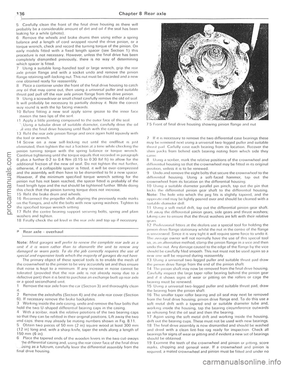
3 USIng a socket through the special holes in the drive lI.::tnge. unsc'ew the bollS secu.ing the b.::tckp late and bearing ,el.::tinor to tho a~le cilSln g (pholo). 11 Withdraw tho a~leshnft. together with the bearing. " it is tight due 10 tho oulor Ir
ig. 8
.6 RelHoving t h o Mdeshalt .e l'l ining hoits (Soc 4)
If
I
/1
II
I
\,
Fig 8 .7 U sing long bolls to ""ithdra"" tho a~leshaft (Sec 4)
cd
procarmanuals.com
Page 136 of 205

m
)
Chapter 8 Rear axle 135
Fig 8 .8 Drilling the beMing rf!t
5 AxlcshiJft homing -renewal
Noto: A SfJL'CI.1f 1001 IS "Hlliller! /0 n'III1:''''''[1 (,0111 lilt' axles/mIl (s,:c Fly 89) 1 Remove the ;,xlushalt as ,h:sG"hcd 1(' St;CIl0n 1 2 Usin\J all 8 mill (0.31 In) dldl, 1Il;,kc a hole III the he,Hlnt! ,etauun\1 119 . t
G Cleiln the l1xlcshnf1. be,non\) ,,,t;WlC' ,Hld "xle C.,1511l\) 7 Locl1le the loe1ll1ll9 HIWlIlel 011 the l1xleshl1lt. followed uy tho new uoa,ing wIth the 001 sel1l [l1CIll\) l1WilY ['om the l1~leshaft Hallge. 8 Slide on the new hea'lIl\) rcta"lIn\) '1119 and pr ess J fully 11\l111l1st tile hearing inner IWck. uSIng a slJItJIJle puller or J ICWlth oftuue. 9 Re fIt Ihe l1xleshalt wllh refe'ence to S ectIon <1
6 Axle reM cover relllov,,1 ilnd refitting
Chock the hont wheels then lilck up the re,l( o f the Cl1r il'l(l SOPPOI1 on axle stands.
2 Cl em1 the reM cover .Jnd surroundIng .Jre" (photo) 3 Remove the hllmlbr"ke relay le ver lind seco nd.Jry cable. or
transverse ,od (as ;;Jpplicilblc) with reletCnce to Ch"pter 9. <1 Place a suitable container helle~th the reM "x Ie to c~tch the oil as the rear cover is removed.
5 Undo and remove t he ten IJOlt s and sprinU washers lhilt securo the reill cover to the llIl,l l drive housillg LIlt aWilY th e re"r cover and its
\Jasko!. ~ Before refitting the ,oar cover Illilke sure thm the mating fJces ilre free of th() old Uaskct or 10nlting compound.
7 FIt a new uasket Jnd then the lea, cover and secure wIth the ten bolts and spring washers. The cover bolts protrude IntO the fillal drive hOUSor1U so it is important that a SUlwble oll·resist.Jr1t scaling
... __ ro*
Fig. 8.9 Usill(J the special Ford tool to removc the axlesllilfl henring (Sec 5)
r;olllpoulid IS SlIll:ilr() d onto lioe Ihro,'ds of each boll bef ore it IS [,twd. 8 TIUhwll tllr: cover secu,,"!.! holls 10 lhe spec,[,ed torque Wfl:IICh
se ttln\)
9 ReCOlillect
Iht! h,lndbr,l~e components with re ference to ChJp ter 9. 10 R efil l ti,e 1e;1I ,ule with the correct 9rJde 01 oil then lower the C,lr to
the UIOUIl(i
G
2 Axle reM cover
7
Pinion oil seal -re"cw,,1
This ope r,ltion may be performed WIth the rear axle in position or on
the benc h
2 Undo ~nd remove the two holts. sprinU Jlld plain washers that secure lhe centre bearing support to the under51(fe of the body (reler to
Chapter 7) 3 With a sc"ber 0' fde. Ill
propeller sha h to ttt() flool I I
J m
procarmanuals.com
Page 137 of 205

Chapter 8 Rear axle 136 )
5 C~rellJlly cle~n Ihe Ir Oll 1 01 the Im,ll d"ve housinU ~s there will Ilroll
P ReM axle -o verh;;lul
Note: Mosl ymilycs wtlf Ilft'h" 10 If.'IWW Iflt' comfllelC IC,ll ,Jxfc ,15 .1 111111 d II IS WOII! ,.II/IC' I/Ioll! 10 rf,SllliI",fc Ille UII/I 10 lel/t·w '''IV r/;/11I.Jycd 01 WOIII poll Is ro do tlw ,ob correclly Icquires Ifle usc 01 spccial <111(1 cxpellsive loofs willch tin' "'",u/lly of y"WY"'S do 1/01 h,lVl' The P"n1
,' . 2 Remove the a xlesh;;lhs (Sec lIon 4) "nd the;lxle ,e". covel (Secllon 6) . If rleceSS;;Jry remove lire !H" ke !liIckpl;,ws 3 WOlk,n!) inside IIlI! axle casUlU . undo .lnd .emove Ihe four bolts th" t hold Ihe IWO U'Shill>cd dlllerentl,ll be"rmg CilPS III the Cilsing. 4 W,lh a sc.iber. m
15 Froni I'll Im
",.IY I,,, ",move(1 Ih:xl uSlnU " ulllvers,,1 two·leuged puliCI and sui!
NOLI! : 1 hu h"le 11110 willch thc peu Irts IS shghlly "'I>c.ed. lind the I>pl''''.'I'! "",1 may he IrIJhLly peelH)d over ;'Iml should he r.:!e;rned with a ·.u,I.II,I" ,".11111;1". ,tr,ll 11 th'''!1 a ... "It IIlI;t.11 dllfl. "'i> out Ihe drllelenli"l p"uon Ue", slr"h. 1.011 .Iw.ly tlr" d,lh;u!Oltl;r1 pinian ue,us. sido {leMS "lid IhruSI was hers; IA"'!l':,"" 10 ell::ure Ih"t the th,usl washe.s ",e lell wllh Ihe ir relative
liP,"" 12 1'",1"~"If)f .. ,1 Il1te.s (It Ihe
procarmanuals.com
Page 146 of 205

) Chapter 9 Braking system 145
/ll.Iid reservoir tille , cap \0 help roduce any fluid loss. 4 Where a rigi d brake line is connec ted \0 the calipe r, comple tely unscrOw the union nUl . Where Iho flex ible hose is connected directly \0 Ihe caliper. loosen only .he union (lnd unscrew Ihc caliper f.om Ihe
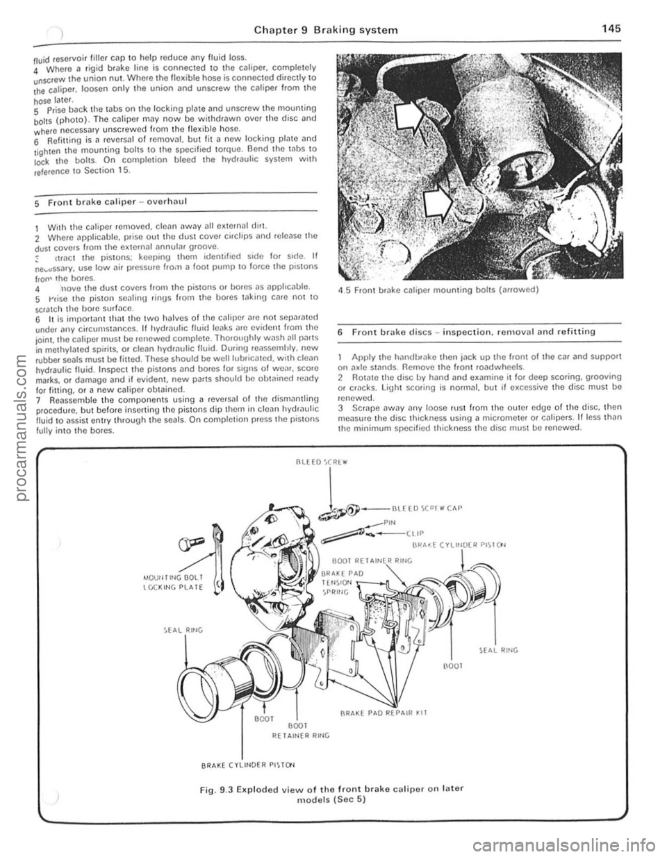
hose later. S Prise back the laus on the locking plale and unscrew Ihe mouming boilS (photo). The cJliper may now be wit hdrawn ove r th o disc and where neCessary unscrew ed from Ihc flex ible hose, 6 Refilling is a revCfsal of fernOv;!I, but lit a new locking plate and
l ighten the mouming bol ts \0 the specified torque. Bend the Inbs \0 Io<:k I he boils. On comple tion bleed the hydwulic system wit h
reference \ 0 Sec tion 15.
5 Front brake caliper -ovorlulU l
1 With the c~liper removed . cle~n away all external dlr1. 2 Where applicable, prise out the dust cover cirClips
IrOIl' lho bores. 4 nove tho dust covers Irom the pistons or bores as apphc
45 Front brake caliper mounting bolts (arrowed)
6 Front brake discs -in spection. re rnovnl and refitting
Apply the hilndlxake then jn ck up the hom of the car and support on :1xle st:1flds. Remove the Iront roadwheels . 2 Rotate the disc by hand and examine il lor deep scoring, grooving or cf1lcks. light scoring is normal, but if excessive the disc must be
renewed.
3 SCrJpe
--
1-""£0""""" ~Plf'l ~-____ ttIP
BI"'~( ".",~"" PI~I()'
4IOUf llltlGOOLI tCCKltlG PLATE
R( 1 Altl{R RltlG
BRAKE (VLIHOER PISTO'l
(l001
Fig. 9.3 EKp loded view of the front brake calipe( on fater models (Sec 5)
RING
., .,
,
procarmanuals.com
Page 147 of 205

Chapter 9 Braking system
4 Note that in order to m,lintOIll even braking both discs should he renewed ill the sal1 1 e lime
5 T o remove il dl~c. first remove the tHlb as described in Chllpter 10 . 6 Prise lip th(J locklllU I"hs. unscrew the fOlll bolts. and remove the disc from Ihe huh.
7 Clcilll the Illllirnu !ilces of the disc and hub then locale the diSC on the huh and allgel the holt holes.
8 InScrt new holt~. tOI){)ther w rth new locking plates. and tiuhten them to the specrfre(1 torque_ loc k b y bending the tabs. 9 Th e huh Illily now he ref Illed with reference to Chapter 10.
7 ReM hrake shoes -rt)rlewal
Check the front wheels th!:n lilck up the rem of the CM lind support on ,1~le stands. Rel(,a5e Ihe handbr,lke lind femove the reM roadwh~~els
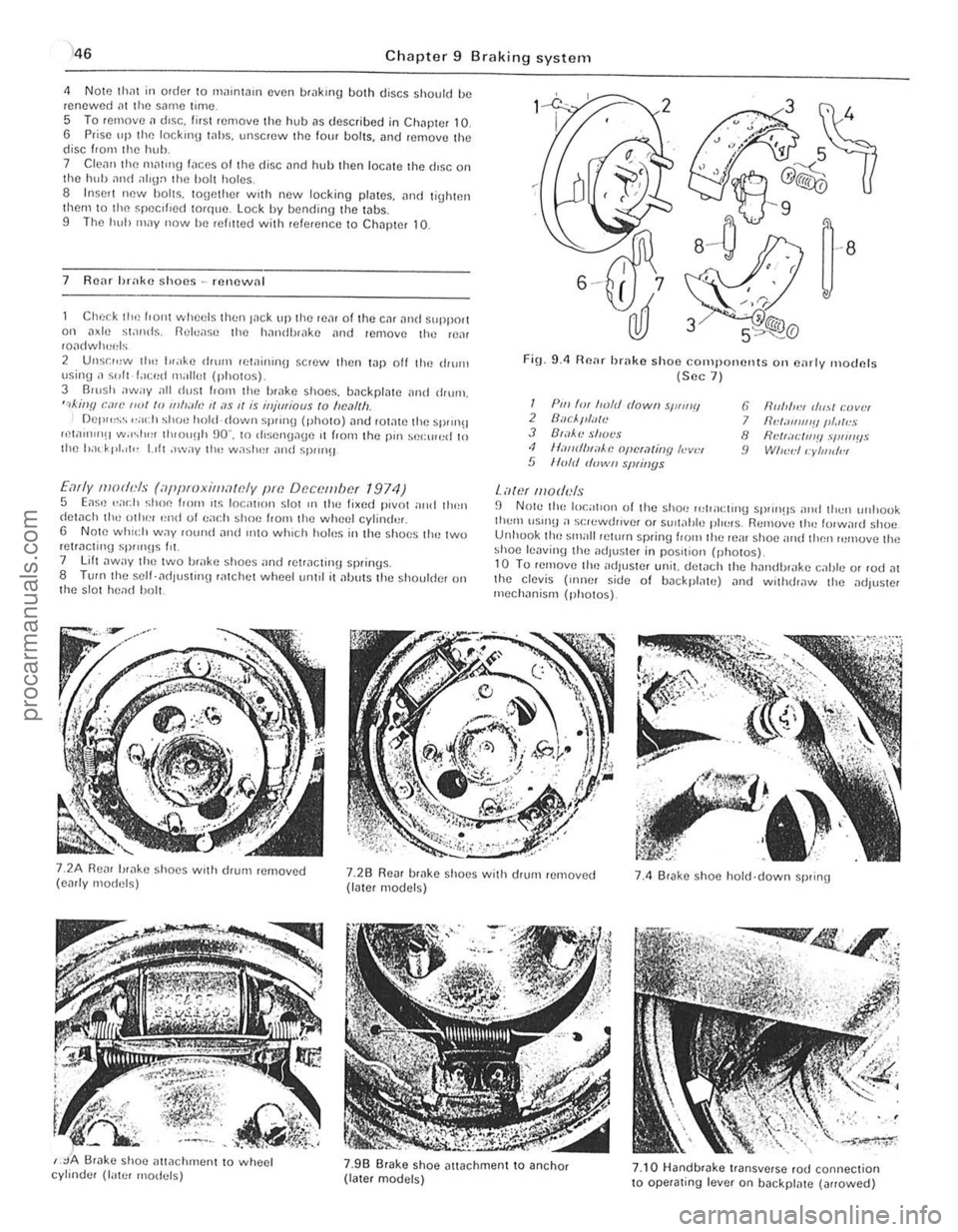
2 Unsr",w th" I"ake drum lewinrnu scrow then t.1p off the ,IIurn \Jsing ;I ~"It f.lced milliet (photos) 3 Barsh away all dust I.orll the brilke shoos, backplate ilnd drum, ",killfl can' ""I /0 11111""., II ;I S 1/ is iHjmiaus to "e,11Ih Del""~~ ,,;och shoe hold-down sprrng (photo) ,lnt! rOt,lte the sprrn!! ",w"nIlH w.r~I"" th,ou!lh 90" , to rhsengage ,t from the pm sel:rr",d 10 Ihe had' pt. 'I" 1.,11 ,"wily 1Ill! w;'shel and spm}!J
Early moth'ls (iippmxilllawly pm Df!c()tllbcf 1974) 5 Eas,) .. ad} shoe loom ,t~ loc;rllol1 slor III the lixed pivot nrrd tllen detach th,-othe! '~nd 01 ea(.11 shoe f,om the wheel cylind'lr, 6 Note whld, W.1Y fOwul and IIltO which holus in the s hoes tlH~ two retracting sP""Hs Ill. 7 lift ,lway t ho two brake shoes "nd retracting springs. 8 TUf(lthe self- ad lust'ng ratchot wheetum,1 it alJuts the shoulder on t he s lot head bolt.
FiO_ 9.4 Renr brake shoo components Oil e,lrly moclnfs (Sec 7 )
I Pili 'm froft! dowII sWIIIII 2 Buc/."liTlt! J B',l~'l! shot's <1 II,-IIIrflHiiAe opcra/jllY h-v", 5 lIo/d d"wII slNil/ys
Lawf lII oduls
6 fir"",,:, (/",,1 r:lJvlH 7 IId;III1I1'!IIII.llr!S 8 flNr;Il:IIl'!! .,'I,"IIIIS 9 WI",,:II:yllJldl!l
fJ N Ole the local,on of the shoe 1"lpacl,no sprrll!ls nrld thell unllook tlwm \lSUl!l a s(;lewrh,vef or SUil;!tJle plo~"s. Remuv,) th" lorw,lrd shoe Unhuok tho small pelurn spring loom the reill shoe and then rumuve the shoe lenvinlJ the adJus!Cr in pos,tiol} (ph o tos)_ 10 Tu remove tim adjuster unit. del
,
j
procarmanuals.com
Page 152 of 205

-
)
Chapter 9 Braking system
,,-
")_'J ,
: ~~ 11111JIII/IIIJ II /I /III Ii hIIllllIlIlIllllIlll 11111#111111 III! -------
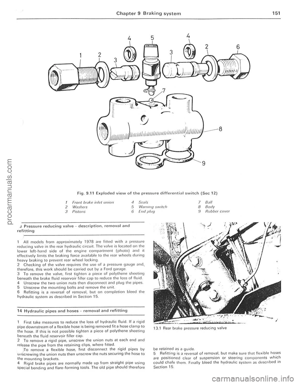
8
9
Fig. 9.11 Exploded view o f Iho pressure d ifferenti
J Pressure reducing vulve -description. remalln' nnd refitting
<1 SCi/Is 5 W,If/ll//y $wl(ch (j [lid ilIIIY
All models from ~pproxirniltely 1978 me lilted with il pressure ,educing valve in the rC~f hydraulic Cifelli!. The IInlve is IOCillCd on the lower Icft- hJrHJ side of the engine compn((mcnt (phOIO) ,mel 11 effectively limIts the hrakin\1 force DV
5 Unscrew the mounting bolts ,md remove the unit.
6 Refitting is a reversal of removal, but on completion bleed the
hydraulic system as descrihed in Section 15.
1 4
Hydraulic pipes and hoses -removal and refittin g
7 8.1/1 8 Body 9 R(lb/w( cover
First wke meilsures to reduce the loss 01 hydraulic fluid. If ~ rig id
pipe downstream of a fle~ible hose is being removed fit ~ hose clamp to
the hose . If this is not possible tighten a piece 01 polythene sheetinu
beneath th e livid reservoi r filler cap. 13
.1
Rear brake pressure reducing valve
2 To femove a figid pipe, unscrew the union nutS;]1 each cnd and release the pipe from the retaining ctrps. wh(Jre /riled.
be retained as a gUide.
151
)TO remove 11 fle~ible hose, lirst disconnec t the rigid pipes IN u"screwing the union nuts then unscrew the nuts securing the hose to
the 1l10unting brackets .
4 RiUid brake pipes arc normally made up from straight pipe using special bending <.rnd flare· forming lools. The old pipe should therefore 5
Refitt ing
is J revNsal o f removal, but make sure thJtlle~ible hoses
arc positioned clear of suspension or steering cOlilpo rwnts which
could chafe them. Finally bleed the hydrauhc system as deSCribed in Section 15.
••
procarmanuals.com