1974 FORD CAPRI oil level
[x] Cancel search: oil levelPage 17 of 205

" ,
'6 Routine maintenance
)
Every 250 miles (400 lUll) or weekly -whichever comes first
Check the engine 011 level and lOp up " OCCCSSJry (Chapler 1) Check and adlus t lhe IYIC pressures (Chilplcr 10) Clean the windscreen and windows C lean the hcadlamps
Every 6000 miles (10000 km) o r six Illonlhs - whichever comes fir s t
£II[1ille (Clwpter 1) Change engllle 011 and IIher
Cleiln oil flilm c"p Chcck 10 1 ,IllY fluid leaka!)e ,n enUme CO'llp:lnUlCIl1
Cooling syslem (Clwptet 2) Check cool:'lnt level
Fuel syslem (Clmpler 3) Check idh"U mi~lUle (cmiJUiello1 IllUdels onlv) al I"SI se.v,ce ollIe, overhaul C heck idllllg sj)ee d
Ignition sys/Cm (C/I,Wler 4) Clean ,1nd re!)"p Sl)".k plu!)s (.:on!nC ' breilkCl Illudels olllv) Cle an and check d'Shibu\o. C"I). '010'. HT lealls mId co.1 (COllWct
bleaker modcls only) Check elwell angle (cOntact b.e"ke. mo
Bri/king sys/Cm (Ch,1pter 9) Check selva
Che ck hydraulic flu id h,vel
Ch(: ck p"ds :'Illd sho(:s lor wear Check h.ake hllcs and hoses
Suspension .wel stvi'ring (Chi/pICr 10) Check tyres 10' w ear and dam:lge Check steering COmp{lIlCnlS l o r w e:l l "lid d.1nlilue
Bodywork. .111d fittings (Clwptef 11) C lu .. >ek se"t belts fa. we .... damage :lnd secwity
Elvc(ric.11 systcm (Ch,7jJ(ef 12 ) Check Ope.iltoon 01 "Uhts Check wilsher flUId levels Check b.1ltery eleclrolvle lev el
Every 12000 miles (20000 kill) or 12 mOll1hs - whichever comes first
III .1(/(lIlioll 10 Ihe 6000 m/le sciler/Ille
Engine (Ch.1f)ter 1) Check and adlUSI valve clearanc es
r"' .......... ~.~-.... ._ •• -.... __ .... . 3lii1&l •
Cooling system (Chapter 2) Check condition "net tension of 1111011)<1101 dflvehelt
Fllel sys tem (Chapter 3) Tighlcn inlel IIHlnl lold boits/nuts Check vacuum hoses Check e~hiluSI syst em Check ll1r ctonne. temperature cOllllol (,I applicable) Renew fuclllllC ' (fuel injec tion models only)
Ignilion system (Chapler 4) lubricate th e dis'flbulOf (conUlel br eake r models only) Renew the coninCt hu,akcr points (II nppllcJblc) Renew the spMk plugs
Transmission (Chapter 6) Check ool/th"d level Lulmc;ue automatIC 1.,'Insmlss,on IInk:'lue
Rcar axle (C/MplCt 8) Check 011 level
Bli/king system (Chaplet 9) Check v,lcuun' hose
llliJllc:'l1C Ihe handhlake Imk,loe
Suspensioll {//j(J swelill!J (C".1plt~( 10) Check condItIon and hlllSlon o f POWI.II ~I!'tllllli dllvthtl1 (II .1l1pllcal,
Check MlspenSlon 101 we;" ;111(1 d;1Il1.1!)e
Bodywork ,1I)d fillings (Clwpler 11) Check opera lion of all locks Check secu.ity 01 dOOf check sl.aps
LlIl)fIcalC locks. door c heck S\','P5 :'Ind fuel fdler cap flap
Check underbody pr olCctive coalm!)
Electrical system (Chapter 12) Check Opcra1l0n of all eleC111!:al IIcm5
Evcry 2<1 000 llIiles (40000 kill) or 2 yc;u s -\Nhichever comes firsl
III ,1(/111/'011 10 the 12000 111"'1 $d'~'f/u/e
[nyino (CIWpICf 1) f!ell'!W crankC:l $e e""5510l1 v;llve
Cooling syslofll (Clwptor 2) Renew COO!:1II1
Fllel SYS(CIII (Ch, '/pliJr 3) Renew"" II Ih!r elemenl
TrallsmissiOIl (ClwjJWr 6) AdjUSI aulom;1\IC trall5nll5SIOll h,ake b;'IIld
Every 36000 miles (60000 kill) o r 3 yenrs - whichever comes first
III .1(/{/I('01l 10 Illc JJIl'VlOUS schc(/ulcs (",lIc" JJJIJ"ci,bfc)
Brakillg system (Clwpter 9) Renew hyd,auhc flUId
procarmanuals.com
Page 28 of 205

)
) Chapter 1 Engine 27
oint t ighten II ~ further 3/4 l urn ~ Remove the t,l ler C,ll> all the left· hand side of the engine and I,ll the g ine with th e correct quantity and grade 01 od (photo), ;n RemOve the OIllcllcl dipstIc k and wipe it clenn. th en fe -insert'! and emove it Jg
(1.76 p int). 10 CICJfl the 0,11,1101 CilP then refit il .
Check and adjust valve cle
hgMel) inlet manifold bolts 12 Remove the ,111 chamiler and \'oh\on the Inlet 111.11"lold hnlls ({J the spec ified lOrque WIth Icfcll!IlCe t o Ch~ptl!r 3 On compl"I")1I ,(:111 Ihe
JII chnmbcI
R enew (fie crankcase ellli,~sion valve 13 pulithe v(1lvl.' (1Pl(I'hose 1'0111 tlw leM 0 1 Ihe "ohl·l1(1nll locker caver
(photo). 14 [1.clc;lse tile cl'll ill1<1 ",movc the v(1lve foorn the h ose 15 Fit the new valve.n levr:rse ordel
3 Major operations possible with eng inc in car
Thc fol lowrng ma lo r operat,ons Cilrl he C;1
,
(It) Rl.'tttOV,ll ollnf ,ellllmg of IIII.' 1".'·(Ofls ilfld cOrlfleelmy rods (,) Rcnewal 01 tI", c ,i/nkslliplt 11(1,,1 Sl'it! rtI IIIIII"y C(lVCI
4 Major operalions requirillg erlgirlo rO!lloval
T he followlllg IHaJOI opernl'OIlS ,,,.IV I", Cill!ICli out ilfl'" 1t'l\1o,",ll of tir e englllC:
(<1) Rcmuvi" iJllr! Id,lllIIY 01 If." ,.,.ttt~Sfti"l .,11(1 II>,1ftl 11,-,tlIIIYS (IJ) !1ellclV,11 ollfw o,wksft,dl II'." .~,.",
5 Methods of engine removal
Althol!OIr It ,~; flo~~lllle to .. ,1)1,,\·,· tI .. , "WIlli': .:Illd U"iU!'vX
o Ellgino rcmovill
II IS t',,-,,.'IIII.-,1 If! h,v" <1 fl
28 E[lO"lc 011 levI;[ d'pstlck ma,kll1gs 2 13 Removing the Cfankc<1se cnHSSIOIl v<1lve
62 Ea'th cable Oil the alte'''''lOl adl"slIllt:l1t u,,,ckel (
Page 60 of 205

)
'tz
Chapter 2 Cooting system 59
1 I VISCOUS (IPlVC I,m coupling (I,~mpc,alu,e sensitIve 1VIle shown) 2.5 Tuppill\l -lIplhc COlllilll1 h,vel in the c~J)alls,on \;lI\k 27 Checkin U the drive-belt IClls,on (28 hire CIlUulC)
2 Routino Illaintcnanco
Altho ,n1C, ... "ls SPOC""]!! utlhe Rouhnc M .. "UcnanCf! SOChOr! on Ihe 110111 01 the m;uu,a1 c;lrIy oul the lol1oWl!ljl p.occduoes
Check cnoling syslcm lor /c,1k.~ 1 In spe cl Iht! coolin!! sysh),l) hose s 'llcludlll!) the ,adIOiIO' :,"<1 Iwate. hoses for damage. detcriOlllll0n i1nd sccullly If Ihelt) is I'Irly IOulle;1I'01] of swelling 01 p
COf/ec t tension If .equir e d .
9 Run the enuine f o r severlll minutes Ihen rec hec k t he lension.
Renew,1/Jtilreeze 10 O.am i1nd flush Ihe CO(lhng System as descrlhed in Sections 3 and 4 . 11 F,II the coollllg system With Ihe correct solullon of watel and amlf,ccle as desc"hed in SeClions 5 and 6 .
3
Cooling sysl e m -drai"inU
If pOSSIble. ensu,e thilt the engine IS cold belo.t! d.al"i"lJ Ihe cool ant. 10 aVOid the fisk of scalding.
2 Remove Ihe .adlatOf or expanSIon tank IIlIe. cap. If the eflUlnc IS hot. Ih ls must be done vl;lry caul,ously, because a sudden release 0 1
Fig. 2.3 Clltawa y view o f Iho expan sio n tlln k showin g tho plastic lovel indicator -tH rowed (Sec 2)
P'".'·S5U'0 CilIl ,esull II. the cool(lnl !.>oIling i1nd blOWing Oul. On ,1 hot enUlIle. plilce iI cluth ove, the caf} and lurn il ve. y uently. '0 release tim p,ess\lIe slowly. 3 flel110ve the SplilSh shield frOI11 b enomh the ra(II;IIOf. of i1pplrcilble
" Unless !he coolilnt IS beinu discarded and thc ca. 's over (I slilt illJle
d'illl1. ,,'"ce a deiln IWO i1nd a half gallon Conl;1ine. underneath the ,adlaIOl. !) Rel110ve the radlatOl bOllom hose lind allow the coo'al11 10 drili" . 6 If the SyStel1'IS to be completely d,ained. rcmove the cyhnde. block d.;1I1' pluU and draIn oul Iho .emainlng coolant hom tho engine . ThiS d'illf' plug IS locilted all the s,de of the cyl inder block to Ihe rear of the oiliolicr. 7 On 1I10deis wilh all eXJ}ilnSlon tank 'emove the rad.alO' cap as well
4 Cooling systom -ftushing
In IUlIe. !he cooling syStel11 Will lose ils efficiency because o f a bu,ld'lIp 01 .uSI and sedunen t in the radiator. To clean the .adliltol. .emove thc IllIer Cill) i1nd 'he bOllom hose ilnd !lush Ihe radialo" by inse.llng a hose in Iho f,lle. car> neck i1nd funninu Wille. th.ough fOf about tr.m I11mules . 2 If Ihere is a Ilea vy aCCUmuliltlOn 01 sediment. it is betler to .eve.se
flu sh Ihe .adl~tor. by connecting the water supply 10 Ih o boltom of the rilclmof alld allowinu II 10 flow oul of the tOIl. Speclnl hose adapters arc avai lable to enahle thIS to be done w ith the rild.ator In I)OSllion. but It is p,efe.able '0 removc the lad,ato. and tum il upside down.
3 Remove t he thernlos,a, (Section 8) then .eve.se lIush Ihe engine wi,h a W1l1e. hose u n lll clean waler flows from the .ndlat Of bottom h ose connectIon.
procarmanuals.com
Page 65 of 205

64 Chapter 2 Cooting system
FiO_ 2.6 Rernovino tho viscous drivn '"n (Sec'1)
A 8 ,,,,,',1/1..·(/ ""f' lock/WI (LH /lorr.;,,') c Mudd"," SIIIIJ!III.'/
1 2 F"n hub bC1lr illg (3.0 litre engine) _ renew .. ,t
Remove
th e drivel>el t (Section 10) then unholt th e 1,111 and pulley. Where il v,scous drive 1,111 ,s j,ued. reler t o Sect ion 1 1. but where ,1 st .. m d;ud Ian is I.Uo
7 F,t;r new a~lr.'I1S'OIl "Iug 10 Ih e 5h
"', '
-.'. c
'
13 3 Disconncchng the wiring hom the l(,rllp .. ",lh "C " .. "tic sellt!.:: . WI't
13 TClllporll\"ro !.F'lIgo sonder ullit -rCr1lov(l1 (lnd refilting
Th ... ICIU IIC'J\U'C UauUc scndc. UII '\'S IOCillcd all the ou\le elbow ,II the f,ont 01 t he cnglllC. 2 H(llc r 10 S "C 110n 3 .. nd d';lllllhc coolm9 system s"H 'Clcrllly 10 bWl!! I he level hclow the auilel elbow 3 Disconnect the w irmS) from the unit (photo)
14 EHpimsion liHlk·· .ernOllill .. nd Icfiu ing
Rohlf \0 Sec tIon 3 "nd d'i"" the coolm!1 system suH,c'Cll1ly 10 hun\] the IOllel billow lhu ""honor la p hose. 2 Unscrew the cross ·hcnd rI10urliing screws ,lfl(t 1I1I the lank from t ht: lIIi1cket (photo).
3 D,sconeet the hoses .. m d remove the e~p;ms'on wnk (photos) 4 RellwnU IS iI reyer s,,' 01 re moy"l. but rel,n th e coohng system as oescr ibeu 'n Section 5
142 Removing th e e~pansion ta nk mounting soews 14.3A Disconnecting the side hose ... 14.36 ... and bottom suppl y hose flom lhe
c~pansion t"nk
procarmanuals.com
Page 67 of 205

)
,
i
I II
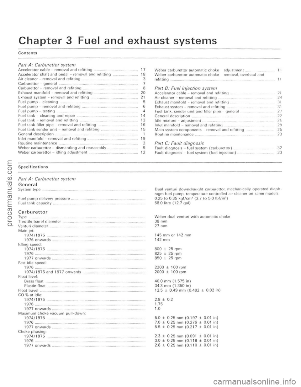
Chapter 3 Fuel and exhaust systems
Contents
Pari A: C,UbufCIIQr system AccchmllOf cable -removal .1n( rerilling , ........... , ...... . Accclm
PMf A: Cilfborettor system
Gctwrctl System 'Y lloC
Fuel pump delivery l)reSS\lrc .
Fuc l I,ln k c,lpnc,'Y .
Cilrhurcttor lytle Tluol1le baf!el dranwtcr
Vcnlull d"ll'ICICI
Mainjct: 1 !I71\/1975 1976 onwards Idlong speed: 1971\/1975 1976 .............. .. 1977onwilfd5 FilSI idle speed: 1976 1974/1975 ilnd HI77 onwilr(ls
Floal leveL: 6111SS lIoal
PlaStic float
Floill Iravel ...
CO %
111 idle: 197<1/1975 1976 1977 oowards ......... ........ , .................... . Maximum choke vacuum p ull down. 1974/1975 .......... ....... .. 1976 1977 onwards ............... . Choke phasing: 1974/1975 1976 .......... .. 1977 onwards,
17 18 3 7 8 20 21 5 6 4 14 13
16
15
1 19 ,
9 12
Weber calburellor
Exh,luSt system .. lemoval ,1nd rnf,ttin!1 Fuel l:lnk. sCIld el utUt and follel l"floC !!fmc.,,1 Gene.;,1 descflpt,on
Irlle nuxture • ,1d/l' Slmenl ..
Inle t man,fold .• emoval and 'ef,nn,!]
Ma,n systcm compo nents .emoval and rd,ll'n!) nouline m.1jnlcn,lnce .
P.1r( C: F.1l1ff di,1gnosis Fintlt d,n!]l1osis .. fuel syslem (cadJll,ello,) Faull d'agnosis -fuel system (fuel injeCI,on) ,
11
"
:12 33
Dual vcnlu.i downcfoa"llhl carh,",cl1or. m~IHI"'Ci,lIv Or.cHnlcd (hap'" .agm luel pump. tempcrilh rrc cOllI/oiled air clenne, on sallHl "'0111:15 02510 0.35 kgl/cm' (3.7 1 0 50 1I,l/ln') 580 Il1re (I2 7 1)011)
Weber (Iunl venturi wilh autorn;rt,c choke 3801111 27 nun
1450101 or 1<12 mill 142 mm
800 J. 25 rpm 825 1. 25 'pm 850 l 25 rpm
noo ,., 100 rpm 2000 ± 100 rpm
40.0 mm (1.575 in)
3 4 .3 mm (1.350 in) 12.5 1. 0 .49 mOl (0.492 L 0 .02 in)
2.8:l. 0 .2 1.75 10
5 .0 1 0 .25 nun (0.197 7.0 J . 0 .25 mm (0.276 5.5 :t 0 .25 mill (0.217
2.3 ± 0.25 mm (0091
, 0,01 , 001 , 0.01
± 0 .01
3 .0 :t. 0 .25 nun (0 118 ± 0.01 2 .8 :l: O .25mm{0.110 J. 0 .01
in)
in)
,n)
in)
in)
III)
procarmanuals.com
Page 71 of 205

70 Chapter 3 Fucl and exhaust systems
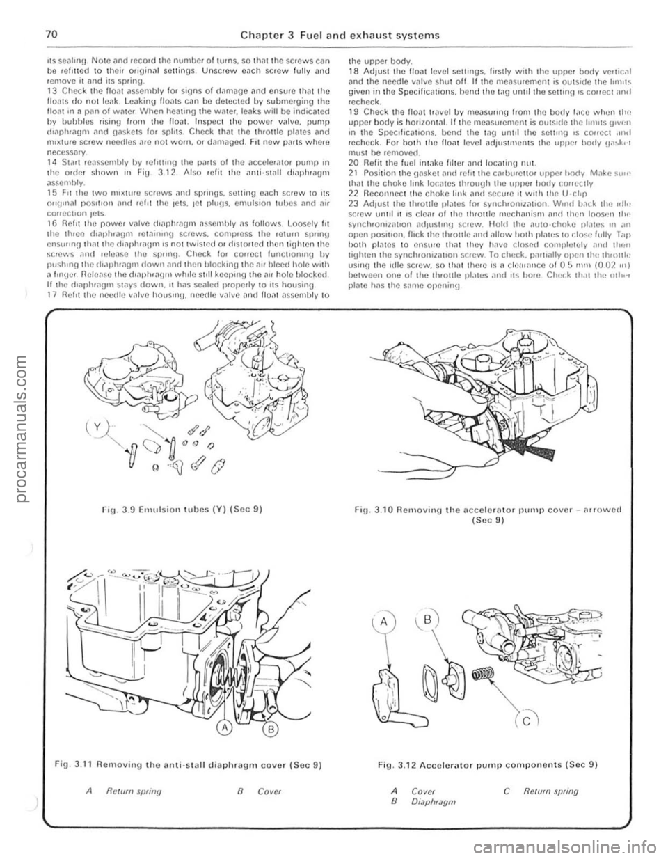
liS seatmu Note ,1nd reco.d the number of lurns, so th,11 the screws can be relltted 10 their orjuin~' settings . Unscrew cilch screw fully and remove it and its SPfing . 13 Che<:k the lIoat
Fig. 3 .9 Emulsion t u bes (V) (Sec 9)
Fig, 3.11 Removin!J tho IIlIli'Slilll dillphragm cover (Soc 9)
Refum sWing 8 Cover
the upper body. 18 Adjuslthe flo." level settings, fi,slly w;l h the upper body verlical .md I he needle villve s hut off lithe meilsurerneot is outsIde Ihe IInlllS given in the SpecifiC
Fig. 3.10 Relllovingllie IIccelcrillor pump cover -(lrrowcd (Sec 9)
..
Fig. 3.12 Accelerator pump components (Sec 9)
A B Covcr Diapl/mom c RC/(lfll swing
procarmanuals.com
Page 72 of 205

) Chapter 3 Fuel and exhaust systems
FiU _ 3.13 Components to he checked (Sec 9)
A
8
C/u':(:A fur wP.olf alJd (/illlli'f/I.l Clwck '(If .~/I"lIitJfJ
C CI)(xk for hd,ill{J {) Check (Of spfrlling
10 Weller cnrhurettor ""tom,lIie choke - rcmov,]L overhaul
and refitlinu
1 DlsconlH!~1 Ihe i)illicry nC\j
le"sselllhly. 11 Ik"ssemhle the choke meCh'1I11SI11. 12 Relit ll1e v"CUUIll til"phl1'lI)lIl alld hOUSII1,). enslllinu th"t lhe (hilphl,l()fIl IS lIolt before lile housing IS fllted. 13 Ensure thm the O-IIllg is correctly locmed in the choke housinU then reCOllnect the lower choke I",k Position the assembly and secure il WIth the thr ee sClews . ensure thnt the upper choke link loc"tes
cOlrectly tluouUh the c"rlJlJretlOf body 111 RecOllllec t the upper choke Imk to the choke Sp"l(tie. 15 Check the V"CUUIll pull· down
Note: lile pfOccc/
.l.I. .... , •• ,. ••. • .. .• . ,,~ ......... , •• , •• .;..,.: .•• ' •.•••• 1 . ;."
.,.', .,1,,/. 1,,' .. 1 . .. . , 1.,.: .. 1,.1.1,.1 .•. : ...
J
Fig. 3.1 4 F loat level adjustment t
.------
./ /' (
Fig.
/
3 .16 Automatic c hoke h ousing alignment (Sec 10)
A Rich c B Normal scl/lllg
marks
71
procarmanuals.com
Page 74 of 205

Chapter 3 Fuel and exhaust systems 73
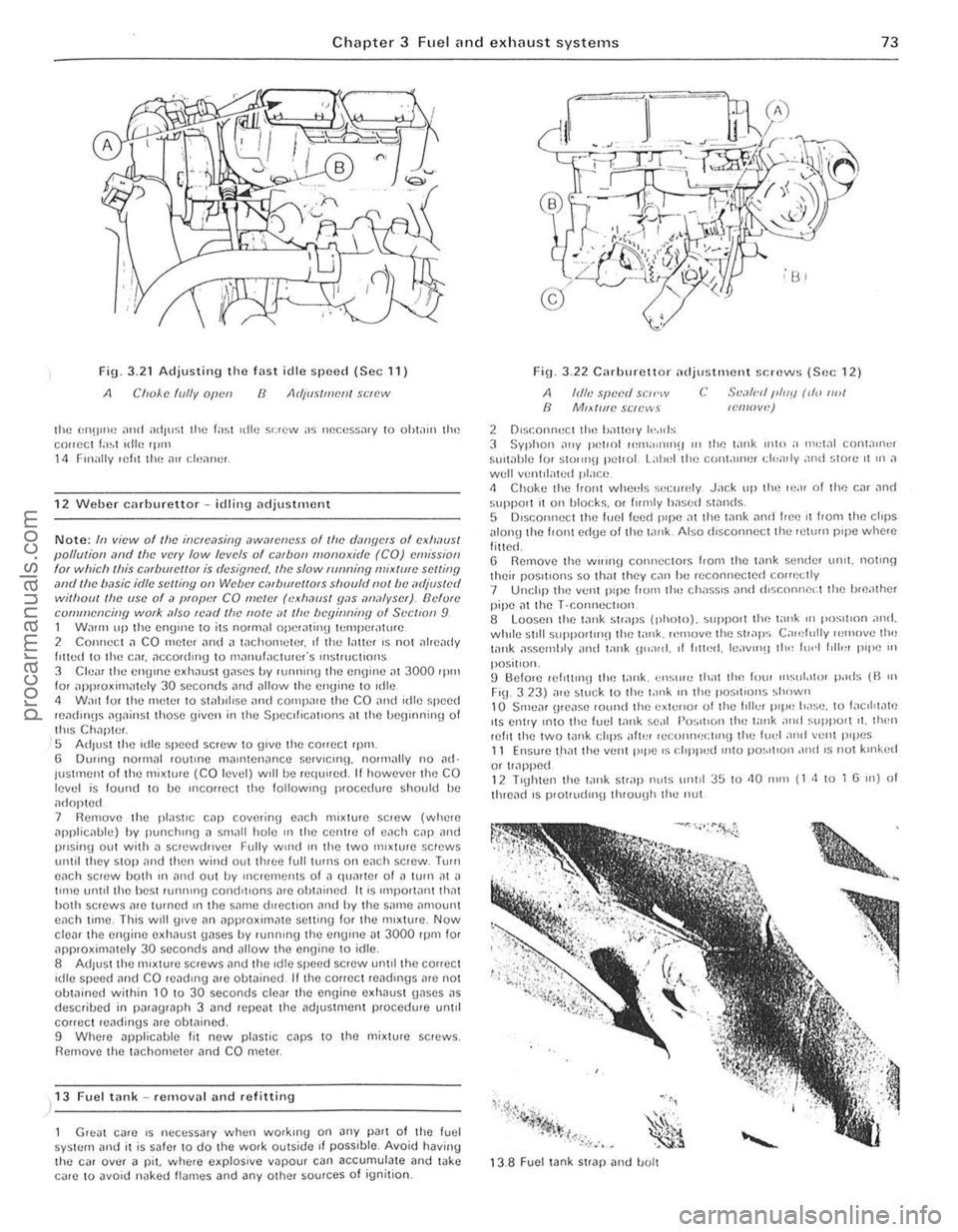
Fig 3.21 Adjusting the fast idle speed (Sec 11)
A Clloke f(llly Olwn ()
the 1:1l!)1I1" alld ;HI)"~;1 lhe lasl ,die s<:rew as llecess;uy 10 ohlain lhe COlleCI la~l I(llf~ 'Ilill 11 Finally felll lhe ,\(I cif,.1ne,.
1 2 Weber carburettor ~ id lilllJ ndjustment
N ote: III view of lfoe illcfem;illg ,1WmeIJeSS ollile d,lI/flefS of exh.lflsl pol/ulioll olml Ihe vefY low levels of cmbol! //Ionuxirle (CO) emission fOI which Ihis e,,,burel/o, is dcsiW!N/. IIIe: slow fUnlling mix/ute: se:l/ill9 ,wd tin' b,lsie idle svlling all WCbt'f e,ltborcl/OfS shoufllllu/lw "djus/cd Wililoll! OW (ISO of a {!fop!"!, CO flfv/ef (c·Xll,lOS! fI"s iflf'lfyser). Bdum CUfluHencillY work ,1150 f(;o1(/ /he flO/t' .11 til<: IW9innilly of Sl'CltOn 9 1 Walm LIp lh(l (ll1gU)(l 10 ilS nounal operalinu If:l1lpCrailH(l 2 COlIIlCCl .1 CO nleler ilnd " lolchol1l(llel. ,I lhe Iilller ,s nOl aire
IUSlrnent of lho mixture (CO levol) w,lIb(l requll(ld. It howevel the CO levcl is lound to be II1COHCCt thc 10110willII p locedwe should be ,ulnp!Cd 7 Rcmove lhe plast,c C
corr(lCl readings me ohwined. 9 Whe,e applicable f it new plas tic cnps 10 the mixture sc,ews. Remove th(l taChOmeler .1nd CO meter.
)13 Fuel tilnk ~ removill .lIld re fittin g
Gn;at c
2 O,sr.onnuct tho !Jallf)ry I,·"ds
c S,.',l/,·" /J/IIY rd,) ,wI lemow.')
3 Syphon o1"y petlOl Ii,,,,a"u!)!) III Ihl"! t,lnk min a 1",,1<11 conwu'"r sUlt
~.* ..... ·0 ~'.~',":L: :~ .. ~" :".~ r~r· .. '.~ . . ' . -
.... ', . ~ , . .
iil~);-< .~:a
1 3 .8 F uel tank StrllP lInd 1!OIt
procarmanuals.com