1974 FORD CAPRI oil level
[x] Cancel search: oil levelPage 120 of 205

) Chapter 6 Manual gearbox and automatic transmission 119
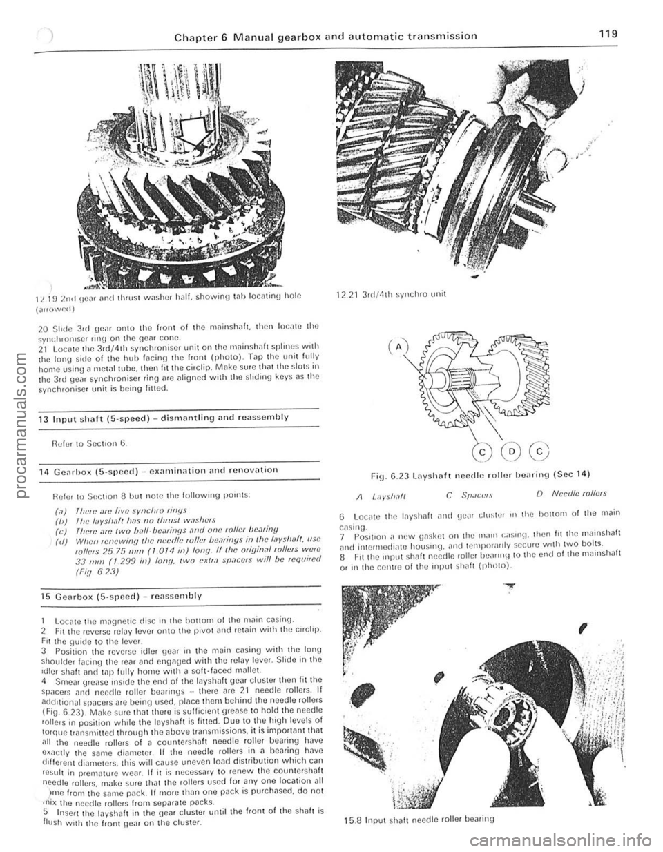
11. 1~) 2nd (Ie", [Inti thrust w,1shcf h.1l1. showioO t .. llloctltinu hole
(",,()w~d)
20 Slide 3ul \jC,lf 01110 the f,aiH 01 the mninsh
13 Input sh(lf( (S·speed) -dismantling Dnd reassembly
!'ld!;! to Section 6
11 GCil,ho)l ([i·spced) -C)lamin,lIion [In(1 rcnov[ltioll
Ref or 10501:[ '0 118 hut now the lollowlng pOllltS :
(,1)
111<:,,) ,1fI! five sYllcll,v rillYs (h) /IlL' I"yshlft lI[1s 110 IIIlIIsl w,lsllt"s (e) (lielL',1ro IWO ball-/)cmiIJYs ,lrId olle ,01lcI hCMiny (d) Wile" ,cnewi"y Ihc IIL'cr/lL' ,01lcI /)(1,1/ill[lS ill I!lc I,Jyslml/, (ISO wllels 25 75 111111 (1 OTt! ill) fony. IIlhc Oligin,ll ,ollers W{!lC 33 111/11 (T 299 ill) lony, two exll,l space's will be requi,ed
(Fiy 623)
15 Gcarbox (5'SI}Cc(l) -rC
Fit the \juidc to the leve r 3 Posit ion the reverse idler \Je~r in the m~in cDsill\j with the Ion,) shoulder facing the reill and en{lllued with thc ,eiDy Icver. Slide ill thc Idler shalt lInci t
)me from t he SMne l"JilCk It more than one pDck is purchased, do not ,ni x lho needlc rol lers from sepilrate p~cks. 5 Insert the layshJlI in the gear cluster unlil the front of Ihe shah is flush With the frunt \Ie~r on lhe cluster.
1221 3 r(I/41h syl1chro unit
Fig 6.23 Layshaft necdle roll.)/ he
G Loc,.tc the lilyshah iln!! gCilr ell/stP' III tho hOllom of the .11il;n
caslnu_ 7 Pos.1I0n ,. n(.'w \Jaskot on the Ill;nll (;;05"'11. Ihen hi the mllinshah ilnt! inlCrll1ed"l\C houslIlg. and IClllpor;I"ly secu.e w,th twO bolts. 8 Fit the mll"t Shilh needte roller heilrrn\J to the end 01 lhe mainshJlt
or In the centle 01 lho input Shilh (photo).
.....
,
~
; , .. '-; . '. ~, .
,
15.8 Input sh
i 1 ,1
I
procarmanuals.com
Page 122 of 205

) Chapter 6 Manual gearbox and automatic transmissio n
121
"
i
...,
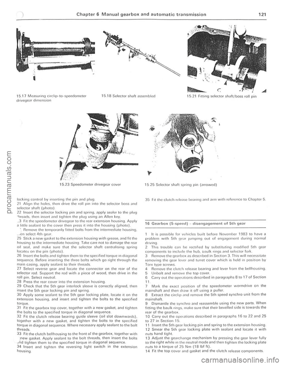
1 5. 17 MC~Sll"nu corchp· 10·SPCI1(lOIllClcr drivcgc,l' dImension 1 5 .1 8 Sc lcCl0f Sholl! t1sscmlJ lcct 1521 FIlling selector sh1lft/boss fall pin
15.23 Speedome ter dJlvcgcn, cove.
IOCkmg cOI1l,ol hy Inserl;"y the 1)111 ;lnd 1>lu9 2 1 Ahgn the holes. then (lillie Ihe roll pin il1lo the sc lcCIOf boss ;111\1 SI~ICC1Of s h
main c .. sing ... pply se
29 Check that the 5th gea. interlock slceve is corrcctly .11ognoo. then 'nscrt thc Sth geil' locking pin and spring.
30 Appl y some scalallt to the 5th geilr locking plate. 10Cilte It on thO extensio n housing. an d inselt nnd t igh ten th e bolts to I h e specIfIed torque. 31 Fit the Ueilrbo~ top covcr. together WIth a new gas\(et. and lighten
the boilS to t he sf1eclf.ed tOfQue in diagonal sequence. 32 F u the clulC h relCilSe bearing guide sleeve (oil slot dow nwllfd s). together with a new gilsket. and lighlen th o boi lS to the specillt~d torque in d;ilgon;11 sequence. Where neceSS;1ry apply seal,.nt to the bolt threads_ 33 Fitthe clutch bell housing to the Iron t 0: the gearhox. together woth new gaske t. Apply sealant to the bolt threads. thcn inse n the boilS .~d tigh ten them to Ihe SIXlcllled 10rQue in diagonal sequence. 34 Inscrt and trgh le n the .ev(usinl.l Ioght switch in Ihe ex tensio n housing
1525 Selec tor sh aft spring pin (arrowed)
35 FIt the clutch reLease l"l'lIIng and a.1Il wuh .efercnce 10 Chnl)\ el 5.
16 G e(lr box (5-spee{l) -d isellg i:lgem enl of 5th gear
I I
is possI ble 'or vducles hu,l t bclo.e NovcmiJer 1983 to have i:l p.oblem WIth 5th ne". Illillplllg Ollt of cnuanClllcn t during normal
(hlv lnu
2 ThiS 1I0uhle Cilll he rcc tl',cd hy suhstitutinu nlod,hc
3 Rem ove Ihe gearbo_ "s de$("bed in SectIon 3. This wrll nCCCSSlla te lemov ing the ge(l' Icvcr "nd lu"C I cove. whIch is held In ,)OSltlo n by TOOK typc sClews . 4 Removo the clutch Hlleilse bearing and tevcl 110m the bclthousing . 5 Unbolt ami lemovc the lOP covel. 6 C"ory out the opel,1t'0"S dcsc llbed in par "graphs 8 10 1" 01 Seclion
" 7 M"r\( Ihe ex.1Ct IIOS""o n of t he speedometcl wormdrive on the milinshil lt (lnd then draw it off using a pulter .
8 Extr"ct the ci. et,p "nd H)move the 5 th sp(lcd sync hro unil/rom Ihe
mJinsh"lt. 9 Dismanlle the synr.hro "nd reasscmble using the new p" rts, When I Itting t he b"ulk lings. m"ko sure that theil bevelle( 1 side is tOwa.ds the
re,,' o f Iho ge",box. 10 Caffy out the ope,,,,,ons desCfibed in jh"lfilgraphs 16 to 22 and 25 1027 in Section 15. 11 Inser t the 5 th ge
procarmanuals.com
Page 123 of 205

, 22 Chapter 6 Manual gearbox and automatic tran smissio n
17 Fllult dingllosis -IlH IIlU
Weak or in effec tive synch romesh
Jumps out of gem
Excessive noise
Exces~ivo difficliity III enonU ing (]0,11
P ART 2: AUTOMATIC TRANSMISS IO N
18 Gen eral description
Thc aulOma llC l,an~nHss'on ,;rkl:~ lhe JlI"Ct~ uf the clutch and Hcmhox. wh,ch ,"c. of cow se . mounte(1 heh,nd lhe enu;ne . The unil has a 1"'{lO nluminl"'" content which helps to .elluc" liS
overall weinhl and 11 IS o f compact dimenSions. All 0,1 coole. 's filled ,IS
Reilson (s )
Sy nchronising cones worn, spilt Of dmnaU ed O~ulk rin g sy nch romes h dogs worn, or dmnagcr!
Broken gcarc h,lnUC fOfk rod spring Selector fo rk rod !IIOOye h.ldly worn
Inen!!cc! 9(,1(10 of oil in gc,llhox 0' 0,1 level 100 low Bu sh or ncc(tie roller hC
l;'lync:u 1hru st W;'\ShCfS w or n ililowing excessive cndplilV (folll,spC
Sliln da.d .. nd ensules cooler OI)(lI.lI1Qn of the \.,lnSUlISSlon lind!)! l.a>l." lowinU ;lnd sunlla. conrll1i0l15 . A VaClIl,Hll conncctlon 10 lhe IIII~I manifold p,ovldes smoO lh cr anrl morc conSI$1r.1l1 clownstlll,S IIndc. load than IS the case Wilh IIn,lS nOl !IlcOlI)Or.11U1IJ lh,s f,,(:Illly The sysle m cotlllJltses lWO tIl.lin com(lonenrs.
(.1) A /"ree e/c'mcnl "v,/lokinc/ic IOUIIIII I:Ollvcrler cOII/,lmy 1:;'I'.1h1(.' o f /orqu c 1II1I!lIplicii /iorr ;, 1 .1/1 irr"mldv Villl;,hle r.1/1O (h) A /unluC/Sln'cd respOlIsiv~ .md IWdwlllrI:illlv IIIIL'f.1lCr! cp'· qL"fie f/c.1rbox COIIII}liSIilf/ pl.wel.l/V m:.lISII/S /IIovidmy tlllf:C forw.l/d 1.1/ios "llff OIlC Icvcrsc ril/'O
Fig . 6.24 C utllw ay view of th e a utomatic transmission (Sec 18)
1 GovelllUi ,'ssemblv 6 rop/leve/sc clu/e h 10 FlOn/ SCIVO 2 GOVlIIJI OI IIlIb 7 FIOIII blilkc bil/Jd /I Valve botlV 3 Olle ·w/lV cfalclt 8 rorquc convenor 1 2 V/lcuum diaplu/lym 4 IlCill bfiJ~C baml 9 Hvdraufic pump 1 J Re/ll servo 6 Forwlllfl cia/eli
procarmanuals.com
Page 124 of 205

Chapter 6 Manual gearbox and automatic transmission 123
When towing a vehic le wIth automl11ic uansmission it is impoltllllt to observe the precautIons gIven til ,he 'Jading and Towing' se<:,ion at the Iront 01 the manual. Due to the complexity of the au'oma',c tran smission unit. If performance IS not up 10 s tandard, or overhaul is necessary, it IS impera tive that this be left to the locallllain agents who will have the special equipment for fault diagnosis and rectiflcallon. The content of the following sections is thereforc confined to supplying gener", Informl11ion 1'Ind any service information and ins t.uc tion tha i cnn be used by the owner.
19 Routine Illilinte,wno
At the i!lle.vnls SI)CClfiecllll Iho ROllllne Milintennnce seCIlOll in the I.onl 01 th e Illanllal cnllY Oul Ihe follOWIng p'ocp.dwe
Luuricow selector link'1[}() , Applv the h;rrldh.,lke th(:n J,lck \lp the front of Ihc Cill ,'lid Support
,n nxle Slnnds
2 Orlthe Irnkn!JCs at cndl end 01 Ihe genrsh ,h rml on the Icfl·hnnd "le 01 Ihe Iransnll~s,on lowel the cnr \0 Iho wound,
Check /mn.Wllissioll fluid level 4 Elrlll!! the engIne and trnnsnllSSlon to nOllllal ope.IlIUl!IIp.llIperillllfe
and I)alk tho vehlchl on le vel grOllnd 5 Wi,h Ihe engIne idllll(l. move tht: 1.,lnsnllSj"on St:leclt>r lev!]r through ill! pOSlllons 1!lIee lImes. Ihen onuaue '1" ,11111 wall for ;rt lea~t one minute. 6 With ,he engine 51111 idling, wllhd.ilW Ihe lr.1nSnllSSIOll d,psllck.
Wipe it dean, reinsert II, wilhd •• 1W 11 for Ihe second !line nnd read off the levol. 7 Two tv pes 01 automatic transnllssion fluid a.e nvarlilblc (sec SpccifiCiltions 10' tv,>c numbe.s) .1nd It is ImpO,I,ln , Ihilt IheV 'lIe nOI mixed. The colour 01 the dipstick. 10' flUId level checklllg denotes which fluid tvpe to use , 8 If a tlr1nsnllssion requlII"U 1,1ter tvpe fluid IS I'lled 10 " to'
adjus'or screw n lew h,fIlS . 13 Tlghlolllhe adJuslo, sOcw to 14 Nm (10 Ihl II) IISIilU a SUItable lo,que wrcnch From Ih,s poSlllon slaCken the adJusle r screw bv exact Iv I'll \Urns (pre·1983 models) or 2 Iwns ( 1983 and late,
model), Ihen tighten Ihe locknut Wllhoul diSlUrblllg Ihe pOsition of Ihe adjuster sc,ow .
14 R econnec t the downshift cable and lowe' Ihe car 10 Ihe ground.
20 Automalic transmission -removal (HId refining
If l)Osslble, ,aise the car on a hOlsl o. place it over an inspectIon pit. Alternatively, it WIll ho necessary 10 Jack up Ihe car to obtain the Illaximum possible amount of wOlking room undernealh. 2 Place a large d.ain pan benealh the transmiss.on sump (011 pan)
Ihen. working horll the ,car, loosen the a!laching boilS and allow ,he lIuld to drain. nemove all thO bohs excep t tho two I.onl ones to draIn as mIlch fluid as pOSSIble, th on temporarilV .efit Iwo bolls at th e re,1I 10 hold it in place . 3 Remove tho Slilrte. moto. as desc.ibed in Chapter 12 . • jWhero apphcable, rernove the access cover Dnd ad3pto, plale bolts,
Ie the engine untrl the to.qu e converter drain plug is visible, then
unsc.ew Iho plug and d.ain Iho Ihud Into a suit3ble con winer. Refl! and l'Uh ten Iho plug.
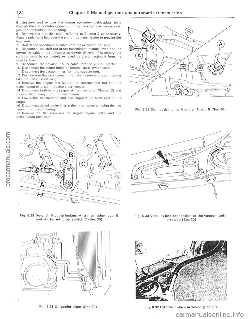
Fig. 6 .25 Checkill{J tho au tomatic transmission lIuid lovel (Soc 19)
Fig. 6.2 6 FrQ,1 bn'ko band adjustment (Sec 19)
A Arllf/SICI sc/t'w a Locknut
C Downslu/t Icvel D Downs/u/t c.lblc
Fig. 6.27 Torquo convorter to driveplato boll -arrowod (Sec 20)
'I
.' i
!
,
{ ,
I , .::
.1 , I, , i:
i 'i; ; I
:1
procarmanuals.com
Page 125 of 205

Chapter 6 Manual gearbo x and auto m atic transmission
5 Unsc rew and remove the tolque conve rter·to·driv eplme b ol ts
t h rough the stader mot o r openrng. turning the engine ,1S neces sary to position the holts rn the opening.
6 Rem ove the propel ler s h alt. reI erring 1 0 Chap te r 7 as necess,u y.
Place a po ly thene bag over the end of t he transmiss io n to preven t dirt Irom ente ring. 7 Detach the sp eedome te r cable from I he extension housing .
8 D iscon nec t the shIft rod althe trans miss ion manual lever. an d the downshift c
selec to r level.
D D isconnect the downshift ouler cable hom the support bracket. 10 D,SCOI1l10Ct th e StMter rnhlbilOr (noullal Start) switch leads. II Disconnoctthe vacuum lines from the vacuunl unll. 1 2 POSItion a Irolley lac k bcne
Fig. 6 .2 8 C onnecting d ips A ,m d shift ro d B (SIlC 20)
-=<
~:=~~3
-: _~e~~-=--'
Fig . 6.30 V ilCUUI11 line connection to the vilcuum unit arrowed (Sec 20)
.... ,' ,',.<.
~
"i'i.
~' ..
F ig . 6.32 Oil fil ler tube - arrowed (Sec 20)
procarmanuals.com
Page 126 of 205

Chapter 6 Manual gearbox and automatic transmission 125
18 Carefully ~ove the lrilnsmission reilrwards ilnd downwmds, and
away from the car. Make sur e that lhe torque conver ter rema ins fully in
the transmission. 19 Refilling is the reverse of remova l but ensure that the torque converter drain plug is In line wIth the hole in the driveplate . To check
that the torque converter is positively engaged. measure the distance A between the converter housing to engine mJting fJce and the end of the $llIb ShilfL This should be al leilsl 10 mm (0.4 in) (Fig. 633). Adjust the selector cilble i1nd inhlbilOr switch i1S deSCribed later ill this Chapter. Reftll the 1riln smission unit with lhe specified flu,d before StDrlll1g the ennine i1nd check lhe level i1S describe(f in Section 19.
21 Selecto r mechililism -removnl. overhnlll ilud refitting
Apply the hnndbr,lke then Inek up the front of the car ilntl suppo'1
on ilxle stands. 2 Insi(fe the cm. prose off th e selector lever escutcheon. ,md wothrhaw
!he Illumillnt,on 1ll0U1l1l1l\J from the selec tor lever Oeneilth the CM. remove the Spr
r(
®---i
A
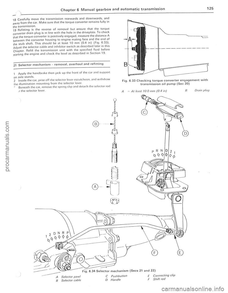
6 .33 Checking torque converter engagement with trnnsmission oil pump (Sec 20)
Alle,1S1 100111111 (0.4 ill) 8 O(.1ill (lluy
:-----
--
6 .34 Selector mechanism (Secs 2 1 and 22)
A SclcclOf pawl B SClccrof cabie
C Pusllbu/loll
o Natld/c
f Connccting clip F Shill (od
.'
. 1 , ;
I
procarmanuals.com
Page 134 of 205

1 Chapter 8 Rear axle 133
Fig. 8 .1 CrOSS-Sl!ction o f cnrlv rCilr ;1xlo (Sec 1)
A Fixed /ellglh SIJ.1C(!f B Pinion slum
2 Routino mnintcnoncc
C Dd1clCII1.11 S/II"'$
At lhe uHerv"ls specIfIed 111 the HOlltmc M.111l1cn;mc c SCCllon III the 110111 0 1 the mnnu;1I c""y oul the following p,uccdw(!.
Check fcar axle oil level 1 Jilek lIlllhc IvaI of the Cil! ;uHf suPPOtl on axle ~I"nds T o C!lSI'''') li1,'l Ihe Cilr is lellel ;,150 I
3 R e
posi tioned lIancnlh the sid(Hllemhe.s . Cho ck thc tronl wheels and rcmove the .ear wheelS . 2 Mark thc p.ol>elle. sh;J1! ilnd .eil'
t'ansverse ,od from the .ea. (Ide wl,h refalCnce 10 Chal >!el 9
5 CI
COUAPS'8ll -----i--i!~e"'.!i SPACH'
,
Fig. 6 .2 Cross·sc ction of I"ter rear Ilxle (See 1)
Fig. 6.3 Removing the rear ax le fillo r 1)lug (Sec 2)
Fig. 8.4 Flexible brake hose connection to the .ear axlearrowed (Sec 3 )
procarmanuals.com
Page 135 of 205

1
134 Chapte r 8 Rea r axl e
FiO. 8.5 Discorlllccti!l9 the rcar sI"biliser Iwr (Sec 3)
7 U~"'!I u"ps (FlU 8 5) I)UU rile s1.1h,l,s(lI b.ll 10 lilt:! lCol. while unstocwIIlIJ the mOlllllnlU I)oIIS from the Ie;)' ;l~II!. flcl110vc the C!JIllI'S 8 W,lh the rC:II Ildc sUlt,lbly SUIlI>o.ICd. lIIlSCICW rhe nulS hom the hallom 01 the U-bolts i1rld reOlOlle rhe lowel S I)llrlU p l;lrcs .. ",t! 1115 .. 1<11015. 9 Wllh rhe help of an asslSlilnt. hft the rem a~lc over the "~
Chock Ihe front wheels then jack up the re,lr of the c~r ilnd support with onle stilnds. Remove the .ear wheel 2 Ilelea se the hilndb.nke and .emove Ihe brake drum.
3 USIng a socket through the special holes in the drive lI.::tnge. unsc'ew the bollS secu.ing the b.::tckp late and bearing ,el.::tinor to tho a~le cilSln g (pholo). 11 Withdraw tho a~leshnft. together with the bearing. " it is tight due 10 tho oulor Ir
ig. 8
.6 RelHoving t h o Mdeshalt .e l'l ining hoits (Soc 4)
If
I
/1
II
I
\,
Fig 8 .7 U sing long bolls to ""ithdra"" tho a~leshaft (Sec 4)
cd
procarmanuals.com