1974 FORD CAPRI oil level
[x] Cancel search: oil levelPage 79 of 205

,
. ,
I , ~. !
78 Chapter 3 FlIer and exhaust systems
TIlls system, when comp1lrcd with conventlon,lI c.Jrhwctlo, ~rrilngemen1s.
tI'(lllPS
A FI/ef Milk Fuef Plllllf! F/lel .?CCIIIIW/<1IOI Fuel filler F/lel ,IISltihular ,w(/ millime con/rol l11ralllc MIlllll/ce/Of "',1/1'115 AI( ch.ll11/"1(
B W
The fuel pump IS 0 1 eh,CIIICtllly operated. ,aile. cell Iyp" A .",SS (IIC rchd ..,:,1..,0 'S mco,p[)I;oh~(1 III the pwnp 10 preY",l! f:XCOSSlvn
p"'SSUIC la"ld III) '" tho event of ,1 ,,)Sl"Ctlon III th e pipelollf!s The fuel ,I(:c\llllula lor ha~ 'wo lunf.luItlS. (t) In 4'ill1I,)(:I1 llll! IIIII,,;,'U)!l 0 1 lhe luclllow. HHlu.:.iI ,ml hy Ihe I)\I"'P ;IIIf' (II) 10 11I;""t,"" Iud I"'"'~''''' ,,1";1 .h" .:o,!.m" h;os Iom,n sw"dn,,' "If TillS p.r.v"rlls .• v; 'po", IIH:1o; .lo.:vel"I'III!1 w,th t:'Hlf.O:'I""nt 100' ~t,'
6
9
The iI" sen~or 1)1"le is locilled in 'he main nIl Stlealll be.ween the iI'r clr:wller ,1nd the Ih'Ol\Io bullerfly. Du'ing idling. the ~irflow hits Ihe sensor plate which in tu.n '
1 Flle/lall/(
"
Mu;/ulc CUIIIIOI ,mif 6 IIIIOlfic pla/c assembly 10 S/;II/ villve 2 Fuel PIIII/I' 5., Fucl (Iistllbutor 7 Inicc/or valvc /I 'hell1JOlimc sw,lch 3 Fuel i'CC/IIIIUI"tul 50 Alf SCIISOI 8 WiJllII·Up regula/or 4 Fuel '"10:1
"'
Plcssule regtllillQI 9 AU~IIt"aIY air device
·.i
<+
procarmanuals.com
Page 92 of 205

Monsurin g plug gnp . gaugo ;;:;;;-;;;"",,',,"," ignition sysICm spccilicalions) should have a sliUht 'drag' when slid between the olocuuch~s. Adjust {[liP if necessary
N orm al. r, dcpo~il~.liUlolly coaled corc nose. increasing by around 0.00 1 in (0.025 mm) pc, 1000 miles (1600 km). Plugs ideally suited to en\j ine. "nd engine in good
condition
Oil fouting. Wet. oily dr~pOl;its. cal,se eventually misfirc. Fllult : wmn bores/ilision 'ingSOf valve guidcs: sometimes OCC"'!! (temj.lO'Hrilyl d .. ring lunning-in
poriOd. Plug~ C()I1 IJ() H! u~ecl "ftc. thorouUh cleaning
-," ..
. \\'
in Electrode demoge. ;;;;,:;;;;;;;:;;;~;~;';::;;i ;;,,, ",,;; h;,
bumed, glazed appearance. Fa ult: pre')gnohon Check: as 101 'Overheating' bllt may be more sovero. Discard plugs ar1d rornedy fault belorc piston or v31vc d~",age occurs
.'
.. ", . ~,'''':c." ~~:~~~~~~::i, Adjusting plug gap. Tlu, plug gap is, 03rth electrode inwards, or oulwards, as I correct clearance is uillaim!d. NOlO II,,! use 01 tho COlfcct tool
spark ami I I' Chock: cMhulOllor , • sellings, 1I0al level ,lIld iot siles; c hoke (lJlOla lion .mel cltlanli n()ss 01 ai, fillel. Plugs can bo rcusod
vlJlue, iunitiun limill H. I"clu t;lillle I1Itillu (tOO lowl
i Split cor o noso (mny npllollI i 8 crBck). Damage is
sel f.evide nt, bUI cruc ks will only showalter cloaning. Faul t: preignition 01 wrOIl!) !)ap settin!) technique. Check : ignition liming,
cooling SYStCIl1. 1",,1 O C t;"" .. r alin!) (too low) and fuel mixlure lton woak) . Discilld "Iu!)s. ",Clllv laul t immediately
procarmanuals.com
Page 98 of 205

Chapter 5
Contents
CIUICh il$scmhty '"SIJoCcl'Qn . Clu\(;11 assembly 'Urn!!ll!) Clutch llsscmhly lemOY," C lutc h cilhle .efluwal._
Clutch
Clutch !Jedal rClllovnl illld ,cflltl"U
Specifictions
Genera l Type ..... Clutch (lise (hamClcr lining tlnckncss Clutch pedal hcc "
Gene.al description
,
5 3 1 8
All manu:!1 transmission madllis covered by this manual nrc lilted Wilh a singlo dl3phrilgll SpllJlg clutch. The unit COlllt)riscs il steel cover which is dowelled and bolted to the tear lace of the lIywheci ilnd conla i.lS the pressure plnte. diaphragm spring and fulCrum .ings . The clutc h " iClio n disc is
ee to slice along the splineJ gearllox
Inpu t Shillt and is held in posi t,on between the flywheel and the pressure plate by the pressure of the pressure plate spring , Friction linIng materiill is riveled 10 the d,sc and II has a spring cushioned hull to absorb transmission shocks and to help ensure a smoo th take oft. The circular diaphrilUm spring is mounted on shoulder pins ilnd
'Ield in place in the cover b.,. two fulcrum rings . The spring is also held ,0 th e pressure platc by three spling steel clips which are rive ted in
posi tion .
The
clu tC h ,s aCluated b.,. a cable controlled b.,. the clulCh pedal.
Clutch '0Ie,150 bCilfl"U -remova' and wl,u,"g Filult (ioilU"OS'S -clutch Generill descllptlon . noutlilc rn,untenanco .
SlIlgle (Iry plate. dlill)hragm sprong. cilhle ·ope.ated 241,3 rnm (95 Ill) 381 nun (0 15 In) 27.01 40mm (1.OG:i 0 .16,n)
No. Ib l It 16 to 20 12 10 15
G 9 1 2
The clutch release mechanism consists 01 a .elease leve. and a bearing which conwcts the lelease Imgers on the pressure plilte assembl.,.. The eHect of an.,. wear of the friction ma terial in the clutch is adjuSled out b.,. means 01 a cable adjuster at the lowel end 01 the cable where it
passes through the bell housing .
Dep.ess lng the clutch pedal actuates the clutch release leve. b.,. means of the cable . The lelease level pushes the lelease bearing
forward to bear against thO release l ingels so moving the centre of the diaphf()gm sprong within the annular rings which act as fulcrum points.
A s th e centrO of thO spring is pushed in. the outside of the Spling is pushed OUI. so Illoving Ihe pressure plme backward and disengaging the p.essu.e plate flom the /tielion disc . When the Clutch pedJI is Icleased. the diaptllaglll spring torces the plessule plate into contac t w ith the frictIon linings on the d,sc and at the saIne t,me pushes it a flactlon 01 an InCh fOlward on I\S splines . The
disc is now fuml.,. sandwic h ed between the plcsswe plnte Dnd the
flywheel. so the d.ive IS laken up.
procarmanuals.com
Page 102 of 205
![FORD CAPRI 1974 Workshop Manual Chapter 5 Clutch
7 2B .. and unhuok Ih" Illller C<lhlr:
6 Wu,k,n\) rn 1111] <:n\)1I1O Gornp"ln",nl pull Ihe ,;alJle Ihouu!)h Ihe
h,Jlkhea d ,n
1l1 Icmuve II trom Ihe Gil 7 Fit the new cahle 1 FORD CAPRI 1974 Workshop Manual Chapter 5 Clutch
7 2B .. and unhuok Ih" Illller C<lhlr:
6 Wu,k,n\) rn 1111] <:n\)1I1O Gornp"ln",nl pull Ihe ,;alJle Ihouu!)h Ihe
h,Jlkhea d ,n
1l1 Icmuve II trom Ihe Gil 7 Fit the new cahle 1](/manual-img/11/56932/w960_56932-101.png)
Chapter 5 Clutch
7 2B .. and unhuok Ih" Illller C
h,Jlkhea d ,n
1l1 Icmuve II trom Ihe Gil' 7 Fit the new cahle 1I;;lnu " levels,, 1 of Ihe lemoval p,ucr.:du,e. Ihen adlust the ped
stcerinu colunlfl 2 Bemove the h:lt hand sp"n\J clip
d'SCOIHleCi Ihr.: cal,l"
B"!1luvlJ ti,,, <:Iuld, pell,,1 plvull"'Sh. E~;,,""'e Ih" 1',,(1;,1 ,Hld hush lu' w,-,ar ,!Ild r! necess
!) Fault dia\)llusis -clutch
Sympto m
Juddcr when laklnu up drive
ClulCh slq)S
Noise when dep,cs$UI\J clutch ped,,1
)
NOIse when ",I"as"'u clutch ped,,1
7 3 R~llII)Vln~J the ~ ,'hh, IrOIll Ihc h"tlhllu ~.n\J
FiU . 5. 4 Removinn lir e "hnch pe{!;!1 (Sec 8)
l1easun(s)
L,u,,,,, '" wr:r,n ""\1"'" ""JUnt'n~l$ (l"ld, d, sc ,;ool,I",,,,. \I'·d w,th 0'1. or 10" ··gs WOlll
Ciu1t: h c"I,l u ~1,~k""J ()I tr"ytd I'"ul ly ple~,>ure pl,He .1,>~e",IJI\'
Clu tc h d,sc stIC~"'\J Oil "'put slr,,1t spl ,o':>
Clul, ·" cirl,I"
I!'o~,," F
WOIII or (lly rul~as,) "~''''"U F
Fau lly Il,u s,>ure pl.lle n,>,>uonbly H,oku", clulCh (j'St; Cl,,>",O,,,og ~PllIlU~
101
,
! '
. , .,
, , I
,
procarmanuals.com
Page 105 of 205

104 Chapter 6 Manual g earbox and autom ati c transmission )
PART 1, MANUAL GEARBOX
Gener"l description
The nl
At the "It,,"v
J.1ck up th,! C;lr amI SUPpO'{ on a xle s!;lIlds. m;lklll\j sure lh"lll 'S levI,1 Alt""l.ltlvely PO~III()n Ihe Cill over .111 "lsfH:r.IIUIl I"l 01 on lamps
) US"'~J ,I s\III, II,le SqLl,lIU key. un~r:",w IllI< hiler pili" f'O'l1 Ilw Idt h;1I1d ~I(h, of Ih(, oe"rI)Ox (pholo) Not" Ihm Oil Ihc lo"r-sp<:ed 11".101)0 the hll", ph,O IS 101:
\Jearhoxes . ,11l(1 f,ve·speed ge.1rhoxes m.1nufactlltud ,,(w, M"y 191;1S (!wlld code FIl) the 011 should be level with (]I a milx"num of 5 0 111111 (02 Ill) helow Ihe iJottOIll edne of the ph)~J hole. I: or ('ve-speed !1(;"'IJ()XI!~ m;lIlufactured liP t o Ap,,1 1984 (Iwlld co(ie EG) Ihe 011 "'list I,,, I"v'" W ill, 11,,; bOllom of Ihe plUH hoi" On I,ve· speed Ilca,hox cs "h"nda<:tu,,,,II,(,twe,)Il M"y 198<1 ,IIld 1\.11111 1985 (Iall sulf,x (,n(iIlHI II'
E) the o'("ltI~1 h" ""'w""" 1 0 0 ""d 150 """ (0 <1 alld 0 G 'n) 1,,;low 110" I)()UDl Il "d~I'! of Ihe I'lu~1 hoi,!
G WI",,,! "'";"s~.,,y top "I' l h " lev,,! with II", ~1'(!<:I(oed !jI;I(),., 0 1 001 (phulo)
" n,,(ot and "!Ih,,,n Ihn fill", plu!) Ihen lowe, Ihe "II to lloe ~)lolllHf
-;;e.1l'lJox -rmll()val ancl .efiuinu
If the IJ"ilrl,ox IS to he 'emov"d from Ih e Cill wllhcHJI romovlIIU Ihe ""II"l(J, Ih" !1'''"j,UX IS rumov,!d Irom heneallo lloe car Jnd il (,IIUe wound cle.11
Fig. 6,1 four-spoed \Joarhox (Sec 1)
Fi\J. 6,2 Five-speed !Jcarhox (Sec 1)
I.e , ..
-~
t 25 W II I !
t A • I I I 15 I
7 (11) no I I ~
~-
" I /
~ 10\,
· ... 1--=" ...
Fig. 6 .3 Wire dimensions for IlHlking a geilrhox oil level dipstick (Sec 2)
All dUllet/SIOIIS J/l IIUn A File lIole/n's
:; .
.. ~ .. -,.' . • <
! ,,;
'r '
,j/
' I
live-speed 25 TopP lng'up the gearbox oil 3 ,4 A On the lIve -spee d UOilfhox remove the pack,n g
procarmanuals.com
Page 107 of 205

·06 Chapter 6 Manual gearbox and automatic transmiss io n
disengilge the gearbox inpu t Shill! hom ,ho clutch p,Iot bearing ,111(1 clu tc h friction disc. I, is imporlanllhal,hc engine and transmi ssion <'lre kept in lino while this is being done. 14 When the gearbox shaft is cleDr of the clutch, remove th e
tran smissio n assembly from bCn(!illh the car.
15 When refiuing, ensure 1il1 the clut ch pilot h earing in the end althe tfilnksha h is ill plilce Jncl is scrviceDble. Tic the clutch lever 10 the clutch housing, 1 0 pr(!venllhe release le.rertrolll slipping out while the ,Wnsmission assembly is being lined. 16 Smear some molybdenum-based grease OntO the end and splines 0' the gearbox input s!mh lind refit the gearbox by reversing the fcmovili p.ocedure. 17 II is impO.IMll when offering up the {jOMOO)(. th,lt il is e~
slightly until the splines enter Do not iluempltO lo.ce the tfilllsmisslOn
ontO thO enlJlnO ThiS Illay (i
'8 Ahe •• el,uinn has been completed. chuck the 011 level Ifl t he .r
Romoye the lou. bolts hom the 1011 cove. 01 the t.ansm.sslon c~t()"sion housin!J ilnd f.om the lri"'snHs~ir)Ol eo'S<' Ilcmovflthc \:oye. s.
t.1king c
R emoYo the .eyerse idle , shah by sc.ewing a suitable bolt into Ihe end of Iho shah and then leye.ing the Sh;'lit Out uSing Iw o open ·ended spanne.s. Fi\)
.
6.6 Removing the seleclor 10lk rolillins (Sec 4)
A CIfC/'11
Fin. 6 .7 Revorso gear interlock nnd light swil c h (Sec 11)
A Ravelse liyh, switch 8 Swing C Plf/ngcr
o h!/ellocl< ball E Sc,ew IJlug
Rct.1ininy bolt F
5 M
thud gear lotwald lly lel/erinu the,n gently wrth a p
their condition. Smear all Pi/ItS wilh tr3nsmission 011 befo.e fitting .
9 Reassemble the synchroniser sleeve and hub so that the nlafks on thorn align . Inse.t the sliding keys and 1IIIhe shdrn\) key sp"ngs so Ihat Ihei. open ends afe stagge.ed re lat ive 10 each other
procarmanuals.com
Page 110 of 205

Chapter 6 M anual gearbo x and autom atic transmission 109
Fig. 6.10 Rcvcrsu [JC>lrill[J '"cill[J fo rwMd s (Scc 5)
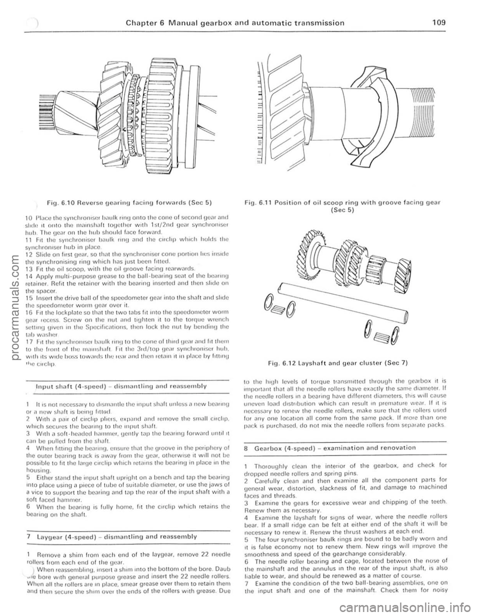
10 l'I:IClllhl} syllchlonl~!"!! t,,1nlk "n[J onlO Ihe COl It! 01 second !Je,'. ,1n(1 511110 11 onl0 I he Ill:H(\sili,l t tOIJlHiler wltil h t/2nd lIe,,, wnclHOlliStH iluh. Thn \In", on Ilw huh should Iilcn 100war d. 11 Fit Ihe sync hronise, lJ;oulk WI(I >llld the c"clop ""Iudl holds th n
sV"ch'Olllser hub in ,)I;lCC 12 Slide on hisl Ulli". so th>ltthe sync hronise. conI.' pO"'Oll 10,,5 ins ide the synch'Onlsing .i"U which ha s lust ~en f'IlC(1. 13 Fit thc oil scoop. wilh the all [JIOOVC lilCinU .e;lfwa.ds. 14 Apply !11ulii-pu'l)oSC [Jrf:ilse to thc billl·hciI.il1!J seilt 01 the ilc,,,,"U rctaine •. flellt the lelllinCf with the be>lll"g insCrtll(1 >llId Ihell slldll on lhe sr)acer. 15 Insetlthe d.ive hall 01 rh e speedo meler geM inl0 rhe sh"lt >lnd shue the spcedomete. wo.1lI ueM over i\. 1 6 1: ,1 I h e loc kpl>lte so thm the twO wbs ht II1tO rhe speedolllelC. wOlin \lCi" I(.'C'"SS Soew all t he not alld tl{.lhlen II to the to.que wICnch
SCllln!) !/,vun III the SI)()Clhcallotls. Ihen lock Ihe IIUt hy bendi"" th C
I"IJ w;osh!"!! 11 Fit lhu synchltJIu~r iJ,IlIlk 1II'!110 thll COliC 01 thUd !Jea. ;lIId lit them to Ihu 1,0'11 01 Ihu I"al,,~,h,,1t ,"It the 3.d/wp !W~. sYlldllOliiSC' huh.
With Its Wide ho~s IOWiUd~ Ihe le,u illid (illlil leWII) I( III pl;lce hy IIlllll!)
"'e t.:llchp
11I1)ut shaft (4·slleed) -dism 'Hlllillg and reasscmbly
It IS
not nccessa.y to (los",,,,lIlc Ihe Input sh
7 lilY!Joa r (4·speed) _ dis milnlling and reassembly
R e
move iI shim Irol11 cilc h end of t he layUMr. ,elllove 22 needle
rolle.s hom each enu of tha \JC
ig .
6.1 1 Position o f oil scoop ring with groove facing gcar (Sec 5)
Fi ". 6. 12lDyshDIt and !Je>lr cluste r (Sec 7)
10 Ihe h'!Jh levels of corque lfanSllulled th.ough the gealbo~ " IS ,mllo.tilnt Ih;)t all the needle rolle.s have exac lly Ihe s,1me dlamele. II Ihe n eed le .ollers ,n iI be,ulng have dlffe.ent (liamelc,s. thiS Will cause
t HIeve" IOile! dls urbu!ion which call .e sul t In prelll;)lu.e we
ThO.oughly cleall the inle"Or of the gearbox. and check lor d.oppcd needle . olle.s ilnd spr ing pins.
2 Ca.elully clean ilnd thcn e xamine all the component pa.ts fOf gene,al wea •. d,stOltion, slilckncss of f it . and damage to IlIac hi ned
I"ces and th.ead s. 3 E~alllllle the gea,s for e xccsslve wear and chipping of the teeth. Renew them as necessa.y .
smOOlhness
procarmanuals.com
Page 112 of 205

Chapter 6 Manual gearbox and automatic transmiss ion 111
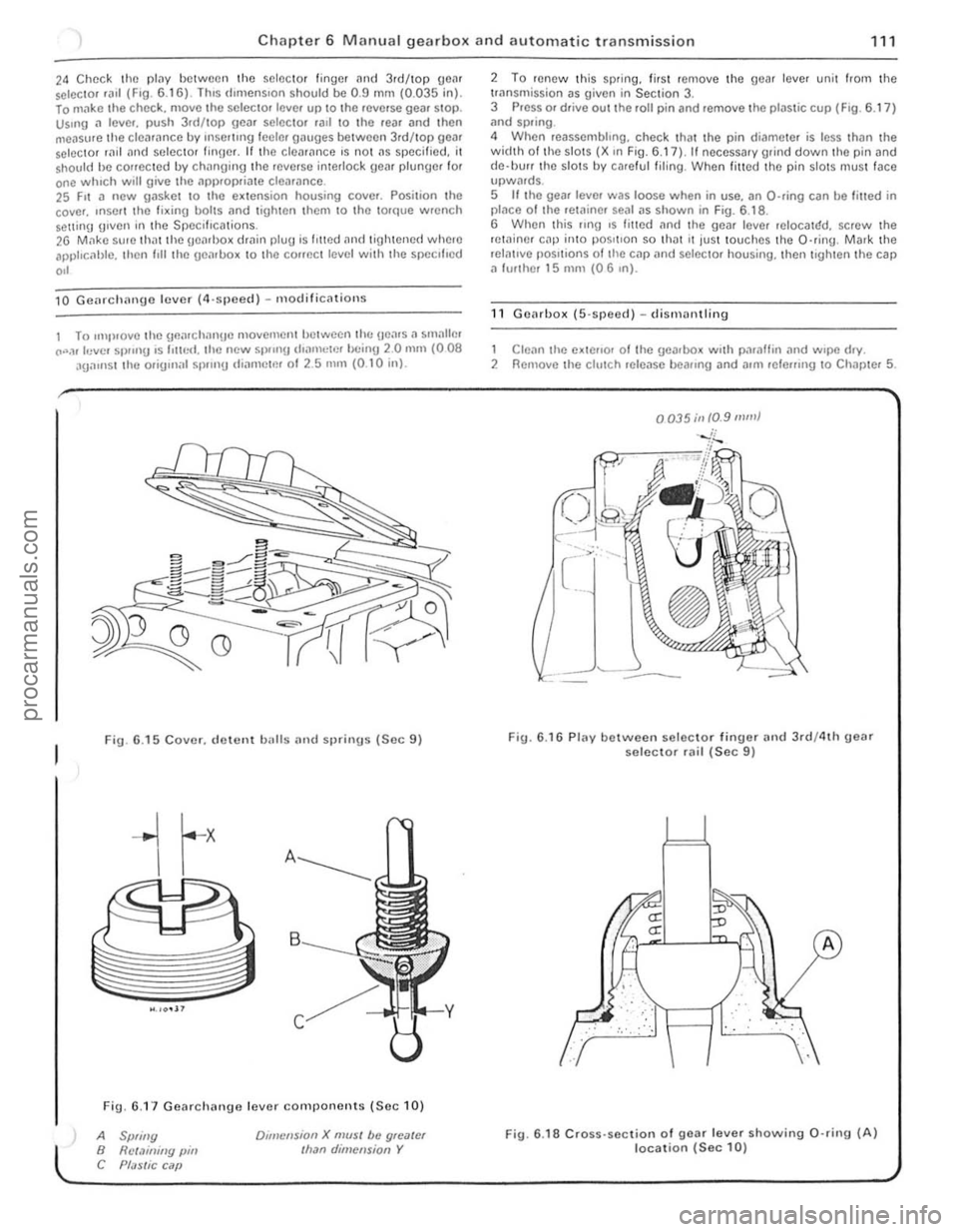
24 Chec k the plilY between the selector finger and 3.d/top geM selC{;lOr .a,1 (F,O. 6 .1 6) . lh,s d,mens,on shou ld be 0.9 mm (0.035 in). lo m"ke t he chec k. move the selec to. leve. up to the .everse gea. SlOp. Us.ng a lever. push 3.d/top gear selector .all \0 the rear and then
measure th e clea .ance by rnsel1lng leeler gauges betwee n 3rd/top gear selector rild "nd seleClOr finger. If th e cleM,mce 's no t ns specified. it shou ld he conecled by chnnging lhe .everse interlock geM plunger for one whIch will give the ,'PI).opria te clearance. 25 F,t a new gasket 10 the e~lension housing cover. Posilion the
cove •. ,nSOI I the fi~ing bolts nnd lighten Ihem 10 Ihe torque wrench Solt1inlJ g,ven in the Specifications. 26 M,1kc su, e th atthe geMl>o~ dmin plug is I,tted and tigh tened where apphc, 1hlc. then I,ll the uenlbo~ 10 the COffect level with the specl l'ed
,,'
10 Gcnrchnnge lever (4,sjleccl ) - m odificnlions
1 To ,mp,ovelhe \]flnr ch nngc movemcntlJctwecn lh(: Hea.s. , smallm CO".,r levcl Sl)!"'g ,s 1'lIr,<:I. the new 51)/,nU d,amclr'!' bc inU 20 mill (008 aga,nst the orig,n;r l sp.,n!) IIiarllctm 01 2.5 nUll (0 .1 0 inl.
Fig. 6 .15 Cover. d ewnt balls and sprinus (Sec 9)
Fig. 6.1 7 Gearchange lever components (Se c 10)
A Spliny B Rct.1illiny pin C Pf;JSlic C ilP
Dlillcnsion X mUSI be gloater Ilran dimension Y
2 To renew Ihis sp.ing. lir sl remove the gear lever unit from the trnnsmission as given in Section 3. 3 Press or drive out the roll pin and remove the plastic cup (F ig . 6.17 ) ;rnd spring .
4 When reassembhng. check that the pin di('!meter is less thiln the width 01 th e slots (X ,n Fig. 6.17), II necessary grind down the pin and
d e·llUrr the slots by ca.e ful filing . When filled the pin slotS mus t face upwMds. 5 If the gear leve. was loose when in use. an O-ring can be filled in placo o f Ihe retainer sOill as shown in Fig. 6.1 8 .
6 When this flng ,s fmed an(I the gear leve. reIOCalr:!d. screw the retainer cap inlO pos,tlon so th ilt It jus t touches th e O·ring . Mark the relntlve pOSitions of tile cap
1 Clean the e~tello. 01 Ihe gearbox w.th paraffin .,nd w.pe d.y. 2 Remove the clutch release beallng and allli lele",ng 10 Chapter 5.
0035;11 10.9 mill}
Fig. 6.16 Plav between selec to r finuer and 3rd/4th geM selector rail (Sec 9)
.. : . :,'. :", .
fLJ
··· ..
A
Fig. 6 .18 Cross· section of gear lever showing 0 ·rin9 (A) location (Sec 10)
i
i
procarmanuals.com