1974 FORD CAPRI brake fluid
[x] Cancel search: brake fluidPage 124 of 205

Chapter 6 Manual gearbox and automatic transmission 123
When towing a vehic le wIth automl11ic uansmission it is impoltllllt to observe the precautIons gIven til ,he 'Jading and Towing' se<:,ion at the Iront 01 the manual. Due to the complexity of the au'oma',c tran smission unit. If performance IS not up 10 s tandard, or overhaul is necessary, it IS impera tive that this be left to the locallllain agents who will have the special equipment for fault diagnosis and rectiflcallon. The content of the following sections is thereforc confined to supplying gener", Informl11ion 1'Ind any service information and ins t.uc tion tha i cnn be used by the owner.
19 Routine Illilinte,wno
At the i!lle.vnls SI)CClfiecllll Iho ROllllne Milintennnce seCIlOll in the I.onl 01 th e Illanllal cnllY Oul Ihe follOWIng p'ocp.dwe
Luuricow selector link'1[}() , Applv the h;rrldh.,lke th(:n J,lck \lp the front of Ihc Cill ,'lid Support
,n nxle Slnnds
2 Orlthe Irnkn!JCs at cndl end 01 Ihe genrsh ,h rml on the Icfl·hnnd "le 01 Ihe Iransnll~s,on lowel the cnr \0 Iho wound,
Check /mn.Wllissioll fluid level 4 Elrlll!! the engIne and trnnsnllSSlon to nOllllal ope.IlIUl!IIp.llIperillllfe
and I)alk tho vehlchl on le vel grOllnd 5 Wi,h Ihe engIne idllll(l. move tht: 1.,lnsnllSj"on St:leclt>r lev!]r through ill! pOSlllons 1!lIee lImes. Ihen onuaue '1" ,11111 wall for ;rt lea~t one minute. 6 With ,he engine 51111 idling, wllhd.ilW Ihe lr.1nSnllSSIOll d,psllck.
Wipe it dean, reinsert II, wilhd •• 1W 11 for Ihe second !line nnd read off the levol. 7 Two tv pes 01 automatic transnllssion fluid a.e nvarlilblc (sec SpccifiCiltions 10' tv,>c numbe.s) .1nd It is ImpO,I,ln , Ihilt IheV 'lIe nOI mixed. The colour 01 the dipstick. 10' flUId level checklllg denotes which fluid tvpe to use , 8 If a tlr1nsnllssion requlII"U 1,1ter tvpe fluid IS I'lled 10 " to'
adjus'or screw n lew h,fIlS . 13 Tlghlolllhe adJuslo, sOcw to 14 Nm (10 Ihl II) IISIilU a SUItable lo,que wrcnch From Ih,s poSlllon slaCken the adJusle r screw bv exact Iv I'll \Urns (pre·1983 models) or 2 Iwns ( 1983 and late,
model), Ihen tighten Ihe locknut Wllhoul diSlUrblllg Ihe pOsition of Ihe adjuster sc,ow .
14 R econnec t the downshift cable and lowe' Ihe car 10 Ihe ground.
20 Automalic transmission -removal (HId refining
If l)Osslble, ,aise the car on a hOlsl o. place it over an inspectIon pit. Alternatively, it WIll ho necessary 10 Jack up Ihe car to obtain the Illaximum possible amount of wOlking room undernealh. 2 Place a large d.ain pan benealh the transmiss.on sump (011 pan)
Ihen. working horll the ,car, loosen the a!laching boilS and allow ,he lIuld to drain. nemove all thO bohs excep t tho two I.onl ones to draIn as mIlch fluid as pOSSIble, th on temporarilV .efit Iwo bolls at th e re,1I 10 hold it in place . 3 Remove tho Slilrte. moto. as desc.ibed in Chapter 12 . • jWhero apphcable, rernove the access cover Dnd ad3pto, plale bolts,
Ie the engine untrl the to.qu e converter drain plug is visible, then
unsc.ew Iho plug and d.ain Iho Ihud Into a suit3ble con winer. Refl! and l'Uh ten Iho plug.
Fig. 6 .25 Checkill{J tho au tomatic transmission lIuid lovel (Soc 19)
Fig. 6.2 6 FrQ,1 bn'ko band adjustment (Sec 19)
A Arllf/SICI sc/t'w a Locknut
C Downslu/t Icvel D Downs/u/t c.lblc
Fig. 6.27 Torquo convorter to driveplato boll -arrowod (Sec 20)
'I
.' i
!
,
{ ,
I , .::
.1 , I, , i:
i 'i; ; I
:1
procarmanuals.com
Page 143 of 205

Chapter 9 Braking system
Fault rflnunosis -hrnking sys tem Foothrnk.c I)(!dnl -removal .1nd refluing From m ake caliper -overhau l .. Front blake cillipCf -removal ;1nd 'Cl,UUl\1 .... ______ ._ .................... . Front brake discs -inspection, ,enlov,,1 and rcl,!\in(J Front disc pilds -renewal , ....... _ ...... .. General description ..... .... ........ . ............ . H andb
Syste m type
I=rOl1t brakes ~c tt,ickncss :
Now ....................................... .
Min rmum.
Oisc fun ·out (ma~inlum including hub).
Mini'l1ulll disc pad lining Ihickness
Re ar brakes MInimum bfake shoe lining thickness.
Torque w re nch settings Caliper ....... ................. ................................... . Brake disc .................... . Backpl"te ........................... .................... .......... ................ .... .. .. .......... . Hydraulic unions. Bleed screw (ma~) .... Aecuf>Cfaling valve 'Clainel (Gi,ling)
Gonoral description
23
16
5 ,
G 3 1 18 20 19 14 15
Oisc brakes aro f;tted 10 Iho front wheels and drum brakes to the lea. wheels. Tho cable or cablo and rod opelilled handbrake oper:11es independently on the real wheels. A vacuum sorvo unit is fiued
" "tween the mastel cytinde. and loolbrake pedal to provide assistance 'en the pedal is depressed.
T he hy,aulic circui t is split frOnt and rear. Undel normal conditions
M,lSIC' cylinder -ove.hilul Milsle. cylinder -removill ilnd .e liuing . P.eSStue d,ffcrenliill swit c h -desoiplion .• e m ov,,1 and .el,ning P,essure ,educing valve · description. relllovill ilnd .er,llonu
Reil' i),lGkplilte · ,emov"r ilnu refining Hei!( i)r"ke shoes -renewal ....... .................. .............. . . Routine m"intenance ........ . ................. .
SlOp·lilmp switch - removal. re/rUlng and ildJustmcflI . Vilcuum servo unil _ description . Vncuum servo unil -rcrnovnl nod rcfiUing Wheel cylindcr -rcmovnl. ove.haul and ref'lIing
11 10 12 13 ,
7 2 17 21 22 8
Dlml hyd'i1ulic cif cuit. snlol Ironl i1nd rCilr WIth IlreSSU,e reducing v:llve in reil r ci.cui t on Iiller models. DISC I,onl brilkes i1nd self·ndjust illu rca .
(!rum brilkes. all wilh servo aSSIstance. Calrle or c.,blc .1nd rod operated handbrake on rear l)f"k es
12 .7 mm (0.5 in) 11.4 rnm (0.45 in) 009 nlln (0.0035 in) 3 .0 mm (0.118 in)
1.5 mm (0.059 in)
Nm 471068 41 1046 271031 71010 10 491062
Ibl It 351050 301034 20 to 23 5 to 7 7 36 to 46
both ci.cuilS operale in unison. howeve •. in the event of faIlure o f one circui t Ihe lemaining ci.cui l will p
Page 144 of 205

) Chapter 9 Braking syste m 143
2
Fig. 9.1 DU
2 ROlltine maintenance
Al III<, u,h!lvals speClficed in the Routine M
2.4 ;-.-
uejJ.es~ the rubue' membrJne to check the fluid low level
Warning IrUht
3 To top up the fluid unscrew the fill er cap whrle holding the c,lhle connector sWtionar y. and add brake lIuid ns necessJr y. R efit the cnp on completion. 4 When checking the brnk e fluid level it is n good practice to also check the low level wnrning light With the hnndbwke rele
Re leuse the hilndb'
Fig. 9.2 Handbr a ke lin k ag e lubrication points (arro\Ncd) on early models (Sec 2)
I .
i
! j..
1:
, ,
procarmanuals.com
Page 145 of 205

144 Chapter 9 Braking systom
9 II there Dre no inspec tion holes, remove the wheels and drums In inspect the linings . 10 Where any lining is less Ih,111 the nllnimufll thickness, renew Ihp. complete SCI 01 re,ll b,~ke shoes. 11 Refi ' the drums lind wheels as necessary then lowe. tho em \0 thl) 9lOund.
Ch eck operation of servo lIoil 12 Visually inspCCllhe vaCUUll1 hose IClIding hom the inlet mlllllfolll Of air box 10 the servo unit fOf dc\c,iOf1l1lon and security. 13 Wit h the engine Slopped. dCI).es s the bra ke pedal several ,imes to dissipate t he VOC U\Ull hoUl the sorvo Imit. 14 Depress the b'i1kc 11Cdll1 wilh moderate pressure then Sin' I the
cnU illC . As the V
R/mew fhe /)rilke I/Ilid 21 lJIucd Ihe hyd.; ."loc sySle m as d"scllherl III Seelloll 15 ilUOwnl! II",
Ihe new h ,,,k\) Ih"d to COnlph: lely 1,lIlhe C:"CUtt he"I!1 bled . 22 AI Ihe sanl\) I"ne rcn,uve Ihe 'Ci" ",ake \I'lOn,s alld check tho wlu,,,1
cylonclers 10' leak"IJe.
3 Front disc pl1ds - renewal
Apply t
he handbr
I .
. ~ .. " ,) •. :Y.
2 RemOV(l Ihe hont wheels.
3 It Ihe fhnd level in the maste' cylondel reservoir is high. when the pistons l1re moved into thei, respecI,ve bo,es to accommodate new pi1ds. thO leyel could rise sulticienlly fo, Iho fluid 10 oyerflow. Place ilhsoruent clOlh .1round the reSe,yO". o. syphon a Imlo Ituid oul. so 1)'Cven tUlg Pil"ltwOlk
<1 F rollt brake caliper _ rcmoy'll iltld refitting
1 nemove the f,on! disc pads i1S tie sc"lJc(/ in Section 3. 2 1111 'S Itll,,,,d,,(1 10 lit ncw Ci1tiper pistoll s "nd/o, seals. dep,ess the tH.1k'J Iwel,,1 10 hlUlU the pistons i"to COI11i1ct with thO (fisc and
'-.. ~
, .
3 .9B Fitting the tenS ion springs
.--.::.:.:; .
....... . ~,'
灲潣慲浡湵慬献捯m
Page 146 of 205

) Chapter 9 Braking system 145
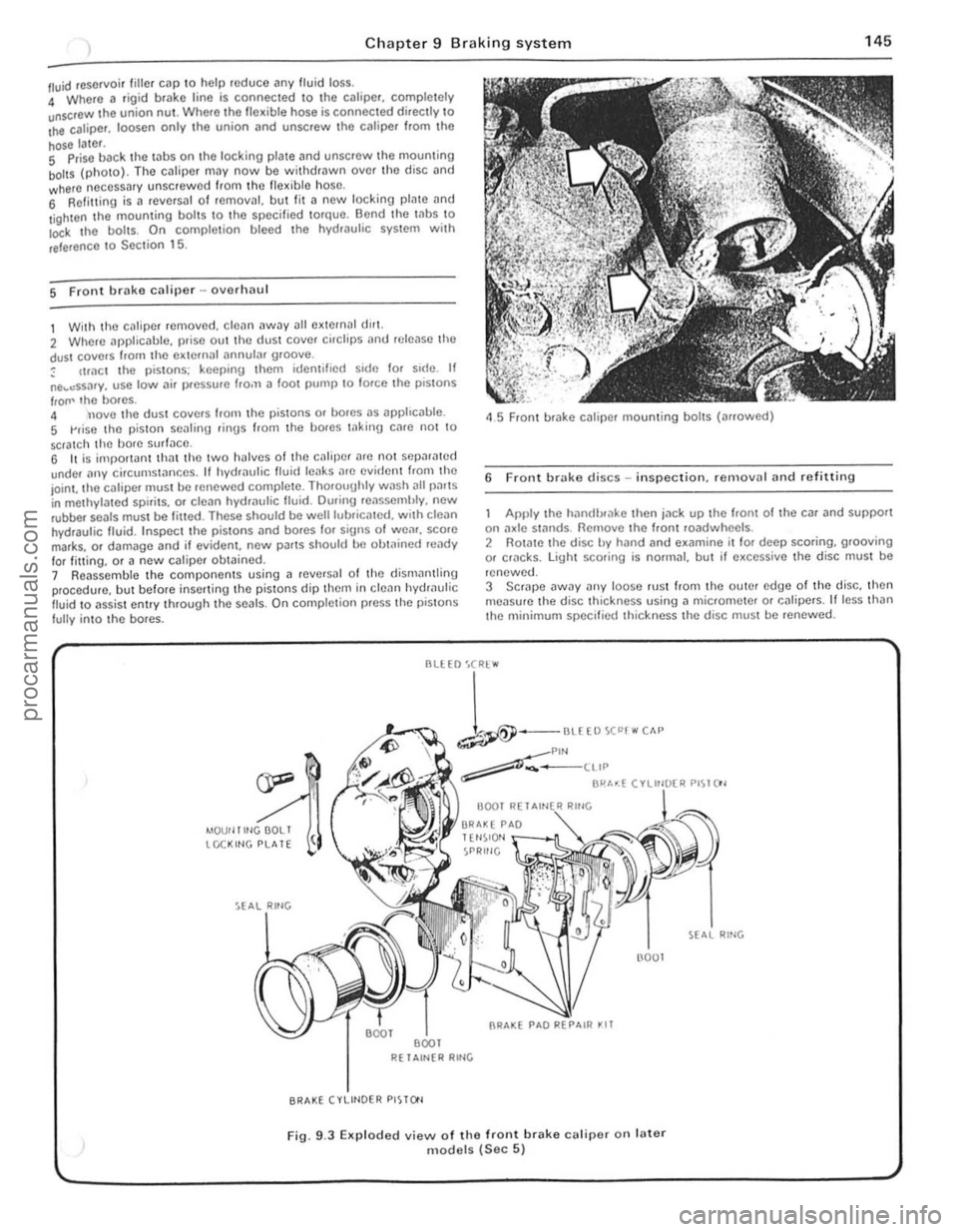
/ll.Iid reservoir tille , cap \0 help roduce any fluid loss. 4 Where a rigi d brake line is connec ted \0 the calipe r, comple tely unscrOw the union nUl . Where Iho flex ible hose is connected directly \0 Ihe caliper. loosen only .he union (lnd unscrew Ihc caliper f.om Ihe
hose later. S Prise back the laus on the locking plale and unscrew Ihe mouming boilS (photo). The cJliper may now be wit hdrawn ove r th o disc and where neCessary unscrew ed from Ihc flex ible hose, 6 Refilling is a revCfsal of fernOv;!I, but lit a new locking plate and
l ighten the mouming bol ts \0 the specified torque. Bend the Inbs \0 Io<:k I he boils. On comple tion bleed the hydwulic system wit h
reference \ 0 Sec tion 15.
5 Front brake caliper -ovorlulU l
1 With the c~liper removed . cle~n away all external dlr1. 2 Where applicable, prise out the dust cover cirClips
IrOIl' lho bores. 4 nove tho dust covers Irom the pistons or bores as apphc
45 Front brake caliper mounting bolts (arrowed)
6 Front brake discs -in spection. re rnovnl and refitting
Apply the hilndlxake then jn ck up the hom of the car and support on :1xle st:1flds. Remove the Iront roadwheels . 2 Rotate the disc by hand and examine il lor deep scoring, grooving or cf1lcks. light scoring is normal, but if excessive the disc must be
renewed.
3 SCrJpe
--
1-""£0""""" ~Plf'l ~-____ ttIP
BI"'~( ".",~"" PI~I()'
4IOUf llltlGOOLI tCCKltlG PLATE
R( 1 Altl{R RltlG
BRAKE (VLIHOER PISTO'l
(l001
Fig. 9.3 EKp loded view of the front brake calipe( on fater models (Sec 5)
RING
., .,
,
procarmanuals.com
Page 148 of 205

Chapter 9 Braking system 147
Br;'lke IlIlInU
Wheel Adjustment
"m
cylinder --·-·_.L
-::'~~:.J/
I
'j
~
l
~
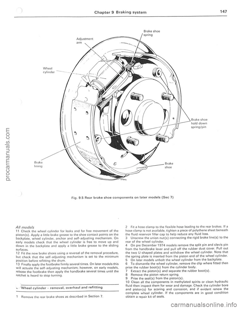
• shoe hold down spring/pin
Br.lke shoe
Fig. 9
.5 Rear brake shoe components on later m odels (Sec 7)
All models 11 Check the wheel cylinder lor leaks and lor Ioee moyemen t of the
piston(s). Apply a hule brake urease to Ihe shoe contac t points on the
backpla te. wheel cylinde r, anchOr and sell-adjusting mechanism. On
early models check th
but check that the self-.. djusting mechanism is set to the minimum
posi tion belore refilling the drum .
13 Finilily apply lhe loo tbrake firmly several times. On later models this will actua1e the self-adjus ting mechanism; however. on e
Wheel cylinder _ remo yal. oyerhaul and re fitting
Remove lhe rear urake shoes as described in Section 7.
2 Fit a hose clalllp to the fle~ible hose leading to the reaf br .. kes. If a hose ci
5 On I.ller models unbolt the wheel cylinde r from the backplate .
6 To dismantle thO wheel cylinder, remoye the clip where fitted then
prise the rubber boo t(s) from the cylinder body.
7 Extr.lct the piston( s)
9 Prise the seal(s) from the piston(s) , 10 Clean all thO compo nents in methylated spirits or clean hydraulic fluid then inspec t them for wea r and damage. Check the cylinder bote and piston{s) 10f scoring and corrosion. and il eviden t renew the
complete w heol cylinder. If the components are in good condition
ob tain a repair kit 01 seals.
i.
i I
II
j
I ;
procarmanuals.com
Page 150 of 205

1 Chapter 9 Braki ng system 1 49
,1 M aste r cylinder -overhaul
With tho m
recuperating valvo. Oepress Ihe primll'y piston during Ihis procedure. 5 Exl.;'!ct Ihe primary and secondary pistons. IOgether wi,h their associated components. noting Ihe order of lemOlln l. H nccessary top Ihe master cylinder on a block of wood or use air pressure from il foot pUIllP through the inlel porlS. G Separate rhe primmy ,10d secondary l)is10 11S irani lha intermediilte
sprinu . Uso tho !inUe.s 10 remove tile Ulilnd seDI from the primil'Y
r""' lon .
The secondil'y piSlon assembly should ho sOfh"ated by lilting the u"mblo leaf ove , Ihe shouldered cnd 01 tho viston . Using the lingo,s.
rr 'wo the se
9 Dotach lhe villve space ,. tilking c
master cylinder on a block of wood or use air pressure from a 1001 pump through tho inlet ports. 12 Prise the seals from the pistons, nOling which way round they are lilled. then il necessary remove tho springs and seals. The prima ry
pis ton spring is retained by a screw.
Both types 13 Clean all tho components in melhylated spirits or brake fluid then
inspec t them for wear and damage. Check the cylinder bore and pistons for scorinu and corrosion. and if eviden t renew the complete nI
1
2~
3~
13
1
2
3
4 5 6
7 8
R
22
21
Fig. 9
.8 Exploded view 01 the Girlin g master cylinder (Sec 11)
Filler cap 9 Seal 16 Secondary piston
Seal 10 MaSler cylinder body 17 Seal
Seal !Clainer
11 WiJslrer 18 Rell11i1er
Fluid reservoi r 12 Reservoir relaining screw 19 Spring
Seal
1 3 Seal 20 Spring fl/Miner
Relainer
14 Primary piSlon 21 Valve
Primary fCCllpCfaling valve
15 Spring 22 Seal
Circlip
10
!
" 1 ,
1
I
!
!
I ,
J
,[
1
I
I
; .
!I ' i ;.
procarmanuals.com
Page 152 of 205

-
)
Chapter 9 Braking system
,,-
")_'J ,
: ~~ 11111JIII/IIIJ II /I /III Ii hIIllllIlIlIllllIlll 11111#111111 III! -------
8
9
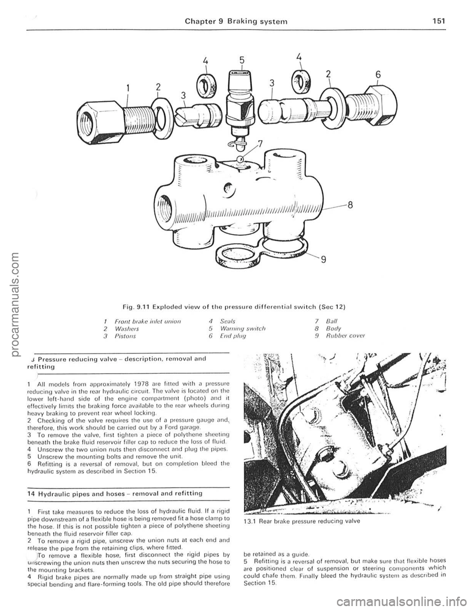
Fig. 9.11 Exploded view o f Iho pressure d ifferenti
J Pressure reducing vulve -description. remalln' nnd refitting
<1 SCi/Is 5 W,If/ll//y $wl(ch (j [lid ilIIIY
All models from ~pproxirniltely 1978 me lilted with il pressure ,educing valve in the rC~f hydraulic Cifelli!. The IInlve is IOCillCd on the lower Icft- hJrHJ side of the engine compn((mcnt (phOIO) ,mel 11 effectively limIts the hrakin\1 force DV
5 Unscrew the mounting bolts ,md remove the unit.
6 Refitting is a reversal of removal, but on completion bleed the
hydraulic system as descrihed in Section 15.
1 4
Hydraulic pipes and hoses -removal and refittin g
7 8.1/1 8 Body 9 R(lb/w( cover
First wke meilsures to reduce the loss 01 hydraulic fluid. If ~ rig id
pipe downstream of a fle~ible hose is being removed fit ~ hose clamp to
the hose . If this is not possible tighten a piece 01 polythene sheetinu
beneath th e livid reservoi r filler cap. 13
.1
Rear brake pressure reducing valve
2 To femove a figid pipe, unscrew the union nutS;]1 each cnd and release the pipe from the retaining ctrps. wh(Jre /riled.
be retained as a gUide.
151
)TO remove 11 fle~ible hose, lirst disconnec t the rigid pipes IN u"screwing the union nuts then unscrew the nuts securing the hose to
the 1l10unting brackets .
4 RiUid brake pipes arc normally made up from straight pipe using special bending <.rnd flare· forming lools. The old pipe should therefore 5
Refitt ing
is J revNsal o f removal, but make sure thJtlle~ible hoses
arc positioned clear of suspension or steering cOlilpo rwnts which
could chafe them. Finally bleed the hydrauhc system as deSCribed in Section 15.
••
procarmanuals.com