Page 170 of 252

DIFFERENTIAL
REAR
AXLE
AND
REAR
SUSPENSION
165
2
Check
wheel
bearmgs
for
damage
or
noise
Replace
them
If
defective
3
Be
sure
to
use
new
011
seals
and
lockwashers
4
FIt
beanng
cup
and
grease
seal
to
cage
Tap
WIth
a
brass
hammer
while
fittIng
FIll
grease
seal
IIp
With
wheel
beanng
grease
after
fittmg
5
Install
brake
diSC
and
beanng
cage
on
axle
Fit
bearmg
cone
With
brass
bar
6
Tighten
lock
nut
Place
faced
Side
of
nut
to
washer
SIde
so
that
washer
IS
not
damaged
Torque
lock
nut
to
10S
to
145
ft
lb
15
to
20
kg
m
7
Match
washer
IIp
With
groove
m
nut
tIghten
nut
and
bend
washer
carefully
to
prevent
hp
damage
S
Use
a
brass
bar
to
fit
011
seal
to
tube
end
When
fitted
apply
grease
to
the
hp
Be
careful
not
to
deform
seal
or
damage
hp
9
Completely
fill
bearmg
With
grease
10
Install
shaft
AdJust
aXial
clearance
With
shIms
See
Figure
37
Clearance
should
be
0
012
to
0
035
m
0
3
to
09mm
Standard
shIm
thickness
IS
0
059
m
1
5mm
@
11
Install
other
shaft
AdJust
aXlal
clearance
With
shIm
Clearance
should
be
0
OOOS
to
0
0059
m
002
to
0
15mm
12
Install
bolts
and
torque
to
26
to
34
ft
lb
3
6
to
4
7
kg
m
REAR
SUSPENSION
PICK
UP
The
rear
suspension
IS
a
banJO
type
ngId
suspensIOn
With
parallel
semI
elhpnc
leaf
spnngs
Front
and
rear
ends
of
the
springs
are
secured
on
the
frame
with
rubber
bushmgs
Shock
absorbers
are
mstalled
on
the
cross
mem
ber
from
the
spnng
lower
pad
Figure
38
next
page
IS
an
exploded
dIagram
of
the
rear
sus
pensIOn
Rear
Suspension
Assembly
Removal
Pick
up
1
Jack
up
rear
of
vehicle
and
support
It
With
stands
Remove
wheels
2
Refer
to
Figure
39
DIsconnect
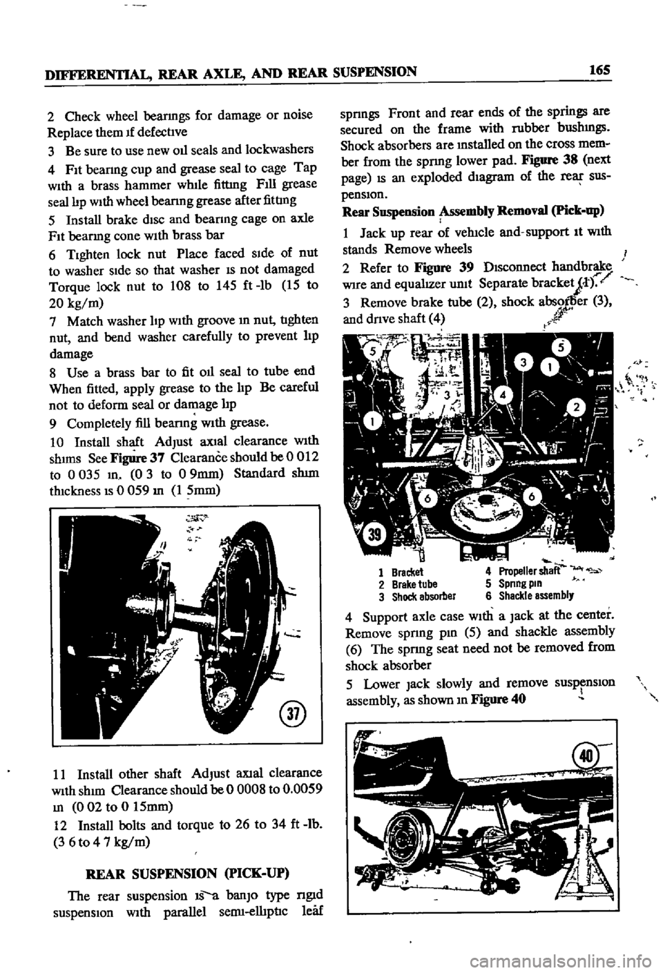
handbrake
Wire
and
equalIZer
unit
Separate
bracketJt
r
3
Remove
brake
tube
2
shock
absorller
3
and
dnve
shaft
4
r
r
0
it
1
Bracket
4
Propeller
shaft
2
Brake
tube
5
Spnng
pm
3
Shock
absorber
6
Shackle
assembly
4
Support
axle
case
With
a
Jack
at
the
center
Remove
spnng
pm
5
aJId
shackle
assembly
6
The
sprmg
seat
need
not
be
removed
from
shock
absorber
5
Lower
Jack
slowly
and
remove
susp
nslOn
assembly
as
shown
m
Figure
40
Page 172 of 252

DIFFERENTIAL
REAR
AXLE
AND
REAR
SUSPENSION
167
REAR
SUSPENSION
pICK
UP
Rear
Suspension
Inspection
nnd
Repair
Pick
up
1
Check
spnngs
for
cracks
breaks
and
general
conditIon
Replace
as
reqwred
If
a
spnng
on
one
Side
IS
replaced
also
replace
the
other
one
2
Check
U
bolts
for
bends
stripped
threads
and
general
conditIon
Replace
as
reqUIred
3
Check
rubber
bumpers
and
bushings
for
cracks
wear
and
general
condll1on
Replace
if
defecl1ve
4
Check
shock
absorbers
for
leaks
or
other
damage
Replace
as
required
Rear
Suspension
Installation
Pick
up
1
Replace
the
rear
suspension
components
m
the
reverse
order
of
removal
2
When
msta11mg
rubber
bushmgs
coat
them
hghtly
With
a
soap
solution
3
Torque
parts
as
follows
Shackle
Pin
Spnng
Pm
U
Bolt
Secunng
Nut
Shock
Absorber
Upper
Nut
Shock
Absorber
Lower
Nut
Dnve
Shalt
Secunng
Bolt
83
to
94
It
Ib
11
5
to
13
kg
m
83
to
94
It
Ib
115
to
13
kg
m
61
to
72
ItAb
85
to
10
kg
m
26
to
31
It
Ib
36
t04
3
kg
m
10
to
12
ft
Ib
1
4
to
1
6
kg
m
18
to
22
ft
Ib
25
to
30
kg
m
NOTE
Retighten
bolts
and
nuts
that
hold
bushmgs
after
vehicle
has
been
removed
from
Jack
and
stands
Page 198 of 252

BRAKES
193
Front
Disc
Brake
Piston
Seal
Replacement
If
oil
leakage
is
detected
around
the
piston
seal
It
should
be
replaced
as
follows
I
Rinse
the
cyhnder
bore
With
brake
flwd
In
sert
new
seal
into
the
groove
taking
care
not
to
damage
It
Attach
the
wiper
seal
Lubricate
cylinder
bore
lightly
With
brake
fluid
2
Clean
the
piston
Inspect
the
pISton
for
scor
ing
or
other
damage
before
inserting
It
Make
sure
that
the
relieved
portion
of
the
pISton
faces
the
pivot
pin
Prevent
tilting
of
the
piston
when
It
IS
mserted
mto
the
cyhnder
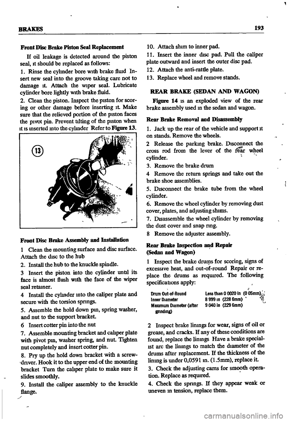
Refer
to
Figure
13
@
4
Front
Disc
Brake
Assembly
and
Installation
I
Clean
the
mounting
surface
and
disc
surface
Attach
the
disc
to
the
hub
2
Install
the
hub
to
the
knuckle
spindle
3
Insert
the
piston
into
the
cylinder
untIl
its
face
is
almost
flush
With
the
face
of
the
wiper
seal
retamer
4
Install
the
cyhnder
mto
the
caliper
plate
and
secure
with
the
torsion
spnngs
5
Assemble
the
hold
down
pm
spring
washer
and
nut
to
the
support
bracket
6
Insert
cotter
pin
into
the
nut
7
Assemble
mounting
bracket
and
calJper
plate
with
pivot
pm
washer
spring
and
nut
Tighten
nut
completely
and
insert
cotter
pin
8
Pry
up
the
hold
down
bracket
with
a
screw
dnver
Hook
it
to
the
upper
end
of
the
mounting
bracket
Turn
the
cal1per
plate
to
make
sure
it
slides
smoothly
9
Install
the
caliper
assembly
to
the
knuckle
flange
10
Attach
shun
to
inner
pad
I
I
Insert
the
inner
dIsc
pad
Pull
the
caliper
plate
outward
and
insert
the
outer
disc
pad
12
Attach
the
anti
rattle
plate
13
Replace
wheel
and
remove
stands
REAR
BRAKE
SEDAN
AND
WAGON
Figure
14
IS
an
exploded
view
of
the
rear
brake
assembly
used
m
the
sedan
and
wagon
Rear
Brake
Removal
and
Disassembly
1
Jack
up
the
rear
of
the
vehicle
and
support
It
on
stands
Remove
the
wheels
2
Release
the
parkIng
brake
DISConnect
the
cross
rod
from
the
lever
of
the
ie
wheel
cylinder
3
Remove
the
brake
drum
4
Remove
the
return
springs
and
take
out
the
brake
shoe
assemblies
5
Disconnect
the
brake
tube
from
the
wheel
cylinder
6
Remove
the
wheel
cylinder
by
removing
dust
cover
plates
and
adJusting
shIms
7
DISassemble
the
wheel
cylinder
by
removing
the
dust
cover
and
snap
nng
8
Remove
the
adJuster
assembly
Rear
Brake
Inspection
d
Repair
Sedan
and
Wagon
I
Inspect
the
brake
druf
1s
for
scoring
signs
of
excessive
heat
and
out
of
round
Repair
or
re
place
the
drums
as
reqUIred
The
following
specificatIons
apply
Drum
Out
of
Round
Inner
Olameter
MaXImum
Diameter
after
IlI1ndmg
Less
than
0
0020
In
0
05mm
8
999
m
228
6mm
1
9040
In
229
6mm
2
Inspect
brake
limngs
for
wear
signs
of
oil
or
grease
and
cracks
If
any
of
these
conditions
are
found
replace
the
linmgs
Have
a
brake
special
ISt
arc
the
limngs
to
match
the
diameter
of
the
drums
after
replacement
If
the
thickness
of
the
limng
is
under
0
0591
m
1
5mm
replace
it
3
Check
the
adjusting
cams
for
smooth
opera
tion
Replace
as
reqUIred
4
Check
the
spnngs
If
they
appear
weak
or
uneven
m
tension
replace
them