1968 DATSUN 510 ECU
[x] Cancel search: ECUPage 115 of 252
110
CHAPTER
NINE
Points
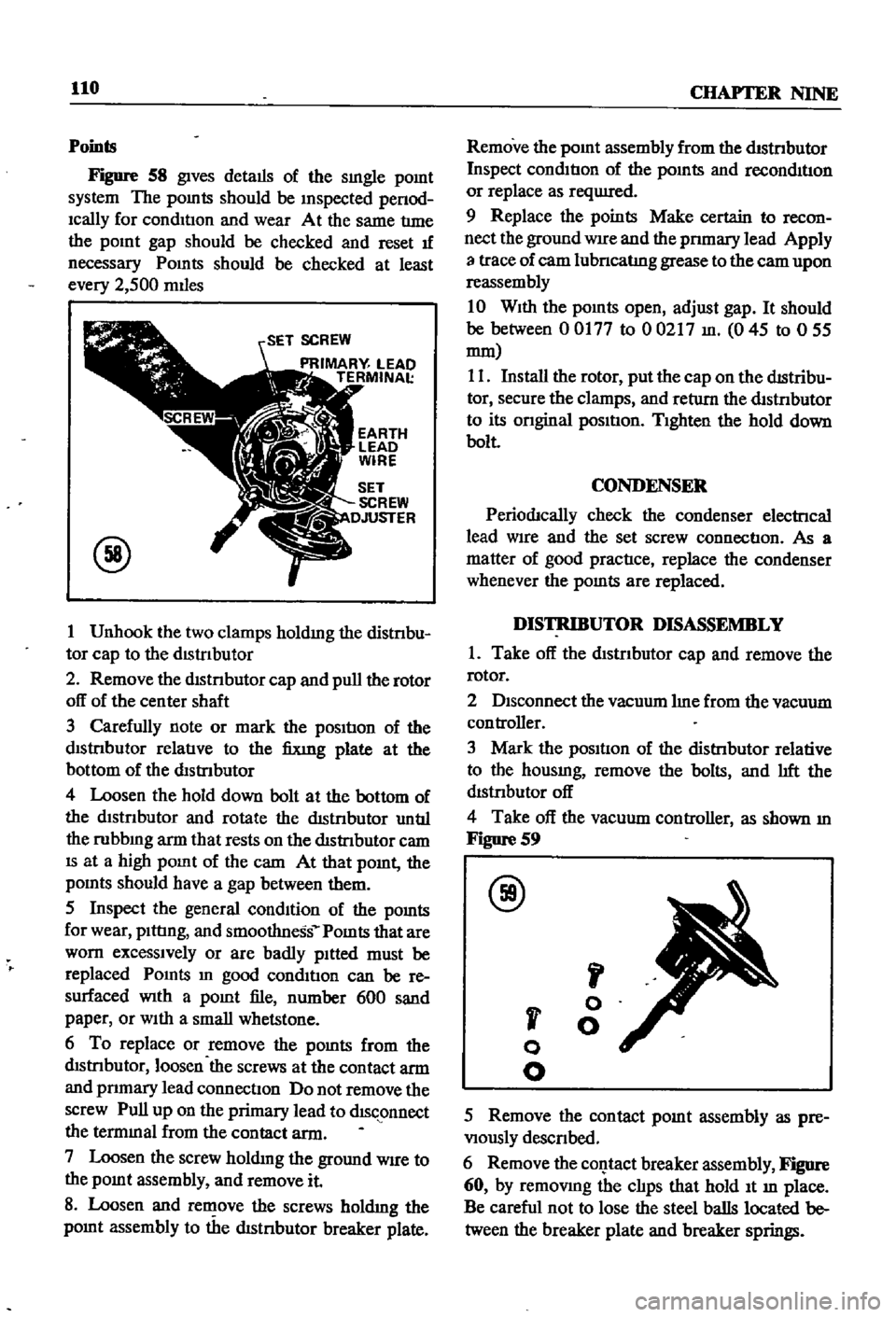
Figure
S8
gives
details
of
the
sIngle
pomt
system
The
pomts
should
be
Inspected
penod
Ically
for
condItIon
and
wear
At
the
same
tlme
the
pOInt
gap
should
be
checked
and
reset
1f
necessary
Pomts
should
be
checked
at
least
every
2
500
mIles
SET
SCREW
PRIMARY
LEAD
TERMINAl
@
1
Unhook
the
two
clamps
holdmg
the
distnbu
tor
cap
to
the
dIStrIbutor
2
Remove
the
dlstnbutor
cap
and
pull
the
rotor
off
of
the
center
shaft
3
Carefully
note
or
mark
the
pOSItIon
of
the
dIStrIbutor
relatIve
to
the
fixmg
plate
at
the
bottom
of
the
distrIbutor
4
Loosen
the
hold
down
bolt
at
the
bottom
of
the
dlstnbutor
and
rotate
the
dIStnbutor
untIl
the
rubbmg
arm
that
rests
on
the
dIStrIbutor
cam
IS
at
a
high
pomt
of
the
cam
At
that
pomt
the
pomts
should
have
a
gap
between
them
5
Inspect
the
general
condItion
of
the
pomts
for
wear
pIttIng
and
smoot1mess
Pomts
that
are
worn
excessIvely
or
are
badly
pItted
must
be
replaced
Pomts
In
good
condItIon
can
be
re
surfaced
With
a
pOInt
file
number
600
sand
paper
or
WIth
a
small
whetstone
6
To
replace
or
remove
the
pomts
from
the
dIStrIbutor
loosen
the
screws
at
the
contact
arm
and
pnmary
lead
connectIOn
Do
not
remove
the
screw
Pull
up
on
the
primary
lead
to
dISc
onnect
the
termmal
from
the
contact
arm
7
Loosen
the
screw
holdmg
the
ground
WIre
to
the
pOInt
assembly
and
remove
it
S
Loosen
and
rell
ove
the
screws
holdIng
the
pomt
assembly
to
the
dIStnbutor
breaker
plate
Remove
the
pOInt
assembly
from
the
dIStrIbutor
Inspect
condItIon
of
the
pOInts
and
reconditIon
or
replace
as
reqUIred
9
Replace
the
points
Make
certain
to
recon
nect
the
ground
WIre
and
the
pnmary
lead
Apply
3
trace
of
cam
lubncatlng
grease
to
the
cam
upon
reassembly
10
WIth
the
pOInts
open
adjust
gap
It
should
be
between
00177
to
00217
In
045
to
055
mm
11
Install
the
rotor
put
the
cap
on
the
dIStribu
tor
secure
the
clamps
and
return
the
dtstrIbutor
to
its
onginal
pOSItIon
TIghten
the
hold
down
bolt
CONDENSER
PeriodJcally
check
the
condenser
electrIcal
lead
wire
and
the
set
screw
connectIon
As
a
matter
of
good
practIce
replace
the
condenser
whenever
the
pomts
are
replaced
DISTRIBUTOR
DISASSEMBLY
1
Take
off
the
dIstrIbutor
cap
and
remove
the
rotor
2
DIsconnect
the
vacuum
me
from
the
vacuum
con
troller
3
Mark
the
pOSItIon
of
the
distrIbutor
relative
to
the
housmg
remove
the
bolts
and
lIft
the
dIstrIbutor
off
4
Take
off
the
vacuum
controller
as
shown
m
F1gDre
S9
@
J
I
v
o
o
o
o
5
Remove
the
contact
pOInt
assembly
as
pre
VIously
descnbed
6
Remove
the
c01Jtact
breaker
assembly
Figure
60
by
remOVIng
the
clIps
that
hold
It
m
place
Be
careful
not
to
lose
the
steel
balls
located
be
tween
the
breaker
plate
and
breaker
springs
Page 127 of 252
122
CHAPTER
TEN
1
Start
the
engIne
and
bnng
It
up
to
normal
operatIng
temperature
2
Inspect
all
hoses
and
connectIons
for
leaks
and
detenoratIon
Shut
off
the
engme
Replace
any
defectIve
hoses
3
Remove
the
hose
attached
to
the
check
valve
4
VIsually
Inspect
the
posItIon
of
the
valve
plate
InsIde
the
valve
body
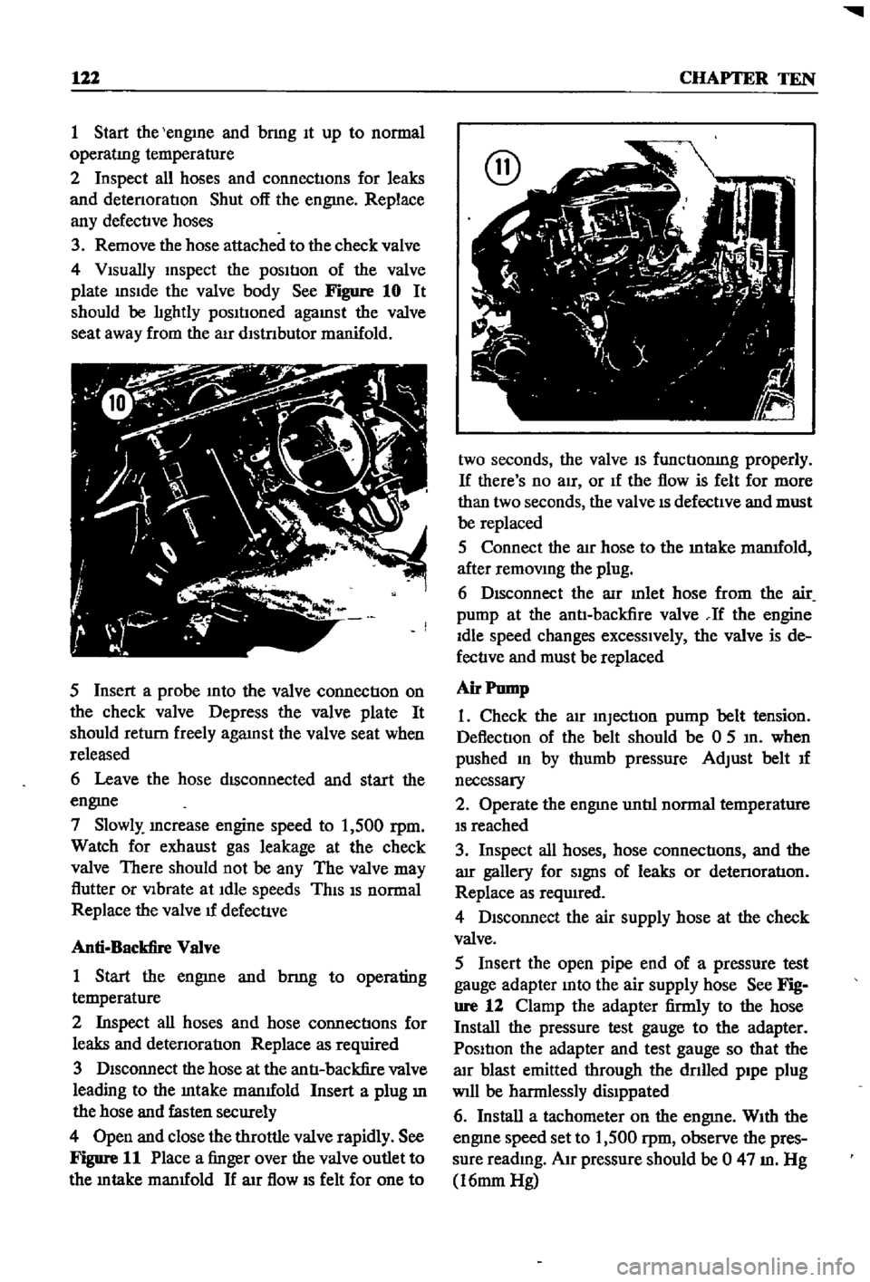
See
Figure
10
It
should
be
lIghtly
posItIoned
agaInst
the
valve
seat
away
from
the
aIr
dlstnbutor
manifold
5
Insert
a
probe
Into
the
valve
connectIon
on
the
check
valve
Depress
the
valve
plate
It
should
return
freely
agaInst
the
valve
seat
when
released
6
Leave
the
hose
dISconnected
and
start
the
engme
7
Slowly
Increase
engine
speed
to
1
500
rpm
Watch
for
exhaust
gas
leakage
at
the
check
valve
There
should
not
be
any
The
valve
may
flutter
or
VIbrate
at
Idle
speeds
ThIS
IS
normal
Replace
the
valve
u
defecuve
Anti
Backfire
Valve
1
Start
the
engme
and
bnng
to
operating
temperature
2
Inspect
all
hoses
and
hose
connectIons
for
leaks
and
detenoratIon
Replace
as
required
3
DIsconnect
the
hose
at
the
antI
backfire
valve
leading
to
the
Intake
manuold
Insert
a
plug
ill
the
hose
and
fasten
securely
4
Open
and
close
the
throttle
valve
rapidly
See
Figure
11
Place
a
finger
over
the
valve
outlet
to
the
m
take
manuold
If
arr
flow
IS
felt
for
one
to
two
seconds
the
valve
IS
functIonIng
properly
If
there
s
no
aIr
or
If
the
flow
is
felt
for
more
than
two
seconds
the
valve
IS
defectIve
and
must
be
replaced
5
Connect
the
alr
hose
to
the
mtake
manuold
after
remOVIng
the
plug
6
DIsconnect
the
aIr
mlet
hose
from
the
air
pump
at
the
antI
backfire
valve
If
the
engine
Idle
speed
changes
excessIvely
the
valve
is
de
fectIve
and
must
be
replaced
Air
Pump
1
Check
the
atr
InjectIon
pump
belt
tension
DeflectIon
of
the
belt
should
be
0
5
In
when
pushed
In
by
thumb
pressure
Adjust
belt
u
necessary
2
Operate
the
engme
untIl
normal
temperature
IS
reached
3
Inspect
all
hoses
hose
connectIons
and
the
arr
gallery
for
SIgnS
of
leaks
or
detenoratIon
Replace
as
required
4
DIsconnect
the
air
supply
hose
at
the
check
valve
5
Insert
the
open
pipe
end
of
a
pressure
test
gauge
adapter
Into
the
air
supply
hose
See
Fig
ure
12
Clamp
the
adapter
firmly
to
the
hose
Install
the
pressure
test
gauge
to
the
adapter
PosItIon
the
adapter
and
test
gauge
so
that
the
alr
blast
emitted
through
the
dnlled
pipe
plug
Will
be
harmlessly
dislppated
6
Install
a
tachometer
on
the
engme
WIth
the
engIne
speed
set
to
1
500
rpm
observe
the
pres
sure
readmg
AIr
pressure
should
be
0
47
m
Hg
16mm
Hg
Page 139 of 252
134
CHAPTER
ELEVEN
CLUTCH
SERVICE
DATA
AND
SPECIF1CATIONS
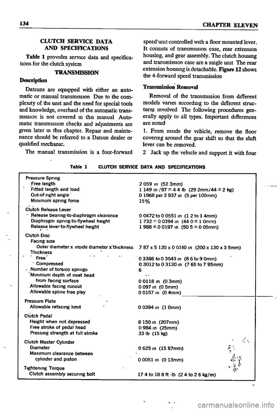
Table
1
proVIdes
serVIce
data
and
specifica
tIons
for
the
clutch
system
TRANSMISSION
Description
Datsuns
are
eqUIpped
with
either
an
auto
matic
or
manual
transrmSSIOn
Due
to
the
com
pleXity
of
the
unIt
and
the
need
for
special
tools
and
knowledge
overhaul
of
the
automatic
trans
mISSIon
is
not
covered
In
thIS
manual
Auto
matIc
transmISSIOn
checks
and
adjustments
are
given
later
m
thIS
chapter
Reparr
and
mainte
nance
should
be
referred
to
a
Datsun
dealer
or
qualIfied
mechamc
The
manual
transmission
is
a
four
forward
Table
1
speed
unlt
controlled
With
a
floor
mounted
lever
It
consIsts
of
transrmSSIOn
case
rear
extensIOn
housing
and
gear
assembly
The
clutch
housmg
and
transmissIOn
case
are
a
sIngle
unIt
The
rear
extension
housmg
is
detachable
Figure
12
shows
the
4
forward
speed
transmission
Transmission
Removal
Removal
of
the
transmIssion
from
dIfferent
models
Varles
accordmg
to
the
dIfferent
struc
ture
Involved
The
following
procedures
gen
erally
apply
to
all
types
Important
dIfferences
are
noted
1
Prom
InsIde
the
vehicle
remove
the
floor
covenng
around
the
gear
shift
so
that
the
shIft
lever
can
be
removed
2
Jack
up
the
vehIcle
and
support
it
with
four
CLUTCH
SERVICE
DATA
AND
SPECIFICATIONS
Pressure
Spring
Free
length
Fitted
length
and
load
Out
of
rlght
angle
MInimum
sprmg
force
Clutch
Release
Lever
Release
bearlng
to
dlaphragm
clearance
Diaphragm
sprlng
to
flywheel
height
Release
lever
to
flywheel
height
Clutch
DISC
FaCing
size
Outer
dIameter
x
inSide
diameter
x
thlckness
Thickness
Free
Compressed
Number
of
tOrslO
1
springs
Minimum
depth
of
rivet
head
from
faCing
surface
Allowable
facmg
runout
Allowable
spline
free
play
Pressure
Plate
Allowable
refacmg
limit
Clutch
Pedal
Height
when
not
depressed
Free
stroke
of
pedal
head
Pressmg
strength
at
full
stroke
Clutch
Master
Cylinder
Diameter
MaXimum
clearance
between
cylinder
and
pIston
Tightening
Torque
Clutch
assembly
securing
bolt
2
059
In
52
3mm
1
149
In
197
4
4
Ib
29
2mm
44
2
kg
o
1968
per
3
937
In
5
per
100mm
15
00472
to
0
0551
In
1
2
to
1
4mm
1732
0
0394
m
44
O
1
Omm
1
988
0
0197
In
505
0
05mm
787
X
5
120
x
0
0140
In
200
x
130
x
3
5mm
o
3386
to
0
3543
m
8
6
to
9
Omm
03012
to
0
3130
m
765
to
7
95mm
6
00118
In
03mm
o
097
In
0
5mm
00157
m
04mm
o
0394
In
1
Omm
8
150
m
207mm
o
984
m
25mm
33
Ib
15
kg
0625
m
15
87mm
00051
m
0
13mm
J
i
r
174
to
188ft
Ib
24
to
2
6
kg
m
Page 144 of 252
CLUTCH
TRANSMISSION
AND
DRIVESHAFI
139
@
1
Re
erse
gear
2
Re
erse
shaft
3
Reverse
gear
4
Snep
nng
5
Thrust
washer
6
Reverse
gear
needle
beanng
7
Counter
gear
8
Counter
shaft
9
Counter
spacer
10
Needle
bearing
assembly
11
Thrust
washer
12
Thrust
washer
J
f
I
I
I
I
I
I
I
I
I
I
J
I
I
i
I
f
4
rm
9
13
MaIO
dnve
gear
14
MaIO
dn
e
beanng
15
MaIO
drl
e
spacer
16
MelO
drl
e
snap
ring
17
MaIO
shaft
18
steel
ball
19
Thrust
washer
20
MaIO
shaft
needle
bearing
21
Meln
shaft
bushlOg
22
MaIO
shaft
flm
gear
23
Baulk
nng
24
Sh
ftlOg
Insert
25
Spread
sprlOg
9
1
Remove
the
drain
plug
and
dram
the
trans
rmSSlon
gear
011
Into
a
SUItable
container
2
Remove
the
dust
cover
and
release
the
re
tainer
spring
securing
the
Withdrawal
lever
Re
move
the
lever
and
release
bearing
from
the
clutch
housmg
3
Remove
the
pIn
securing
the
strikmg
rod
to
the
control
lever
and
remove
the
control
lever
4
Remove
five
front
cover
securing
bolts
and
the
front
cover
i
j
5
Remove
14
hex
bolts
and
washers
from
bot
tom
cover
Remove
bottcifu
cover
from
trans
I
I
I
I
I
I
i
i
J
34
34
26
Synchronize
hub
27
CoupllOg
slee
e
28
MaIO
shaft
needle
beanng
29
Second
gear
assembly
30
MaIO
shaft
needle
beanng
31
Third
speed
gear
32
Baulk
nng
33
ShlftlOg
IOsert
34
Spread
spring
35
Synchro
hub
36
Slee
e
coupllOg
37
Snep
nng
38
MaIO
shaft
pilot
beanng
39
Main
shaft
bearing
40
MaIO
shaft
snap
ring
41
Re
erse
maIO
gear
and
hub
set
42
Rwerse
hub
maIO
shaft
43
Speedometer
gear
44
Steel
ball
45
MaIO
sheft
loc
l
washer
46
MaIO
shaft
nut
28
iy
25
25
21
rmssion
case
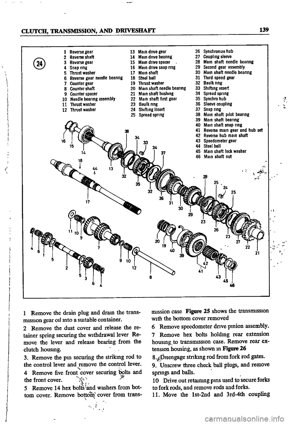
Figure
25
shows
the
tranSmISSIon
With
the
bottom
cover
removed
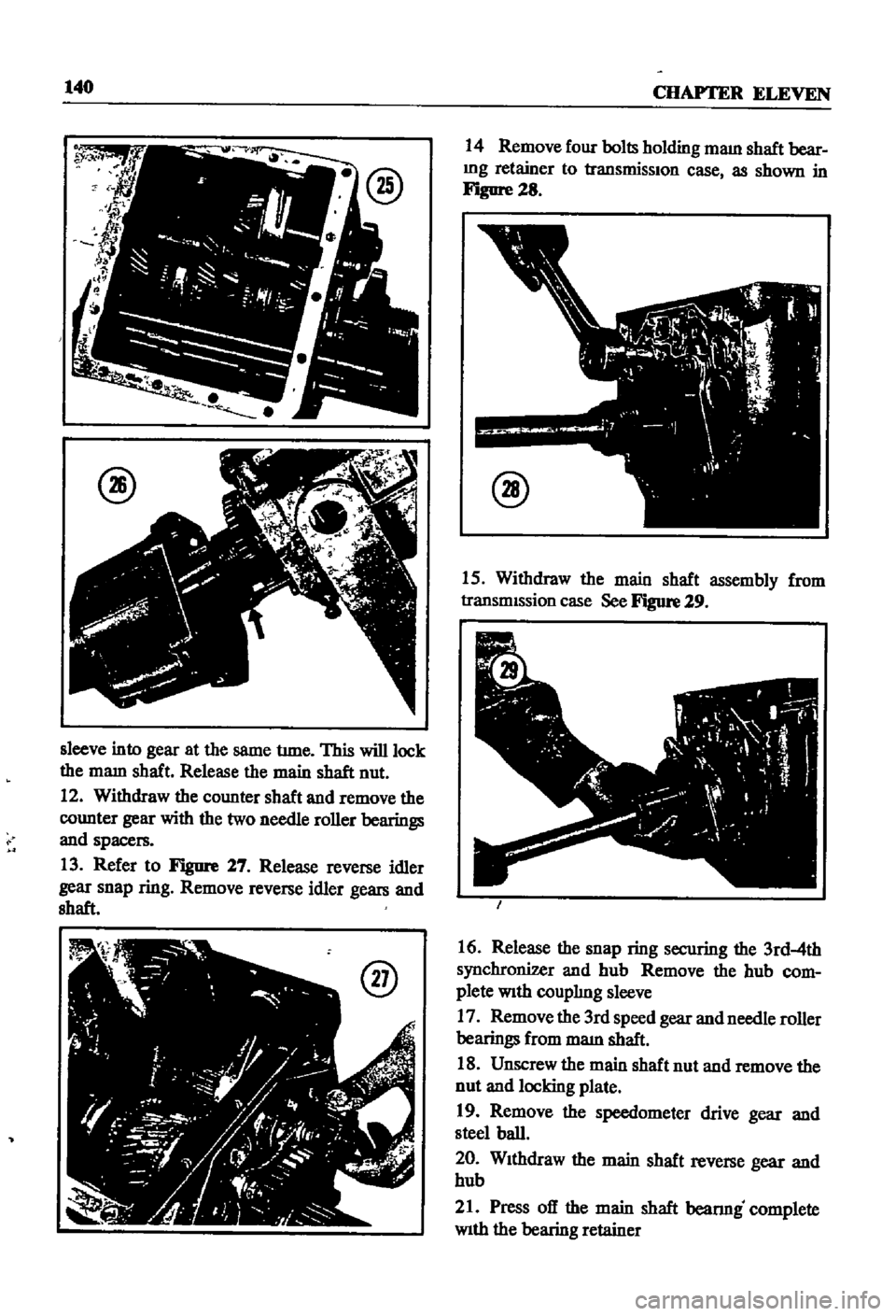
6
Remove
speedometer
dnve
pmion
assembly
7
Remove
hex
bolts
holdmg
rear
extension
housmg
to
transmISSIon
case
Remove
rear
ex
tenSIon
housing
as
shown
m
Figure
26
8
fDlsengage
stnkmg
rod
from
fork
rod
gates
9
Unscrew
three
check
ball
plugs
and
remove
sprmgs
and
balls
10
Drive
out
retatnmg
pms
used
to
secure
forks
to
fork
rods
and
remove
rods
and
forks
11
Move
the
1st
2nd
and
3rd
4th
coupling
Page 145 of 252
140
CHAPTER
ELEVEN
@
sleeve
into
gear
at
the
same
tune
This
will
lock
the
mam
shaft
Release
the
main
shaft
nut
12
Withdraw
the
counter
shaft
and
remove
the
counter
gear
with
the
two
needle
roller
bearings
and
spacers
13
Refer
to
Figure
27
Release
reverse
idler
gear
snap
ring
Remove
reverse
idler
gears
and
shaft
@
14
Remove
four
bolts
holding
maIn
shaft
bear
Ing
retainer
to
transmissIOn
case
as
shown
in
Figure
28
@
15
Withdraw
the
main
shaft
assembly
from
transmIssion
case
See
Figure
29
16
Release
the
snap
ring
securing
the
3rd
4th
synchronizer
and
hub
Remove
the
hub
com
plete
With
couplIng
sleeve
17
Remove
the
300
speed
gear
and
needle
roller
bearings
from
maIn
shaft
18
Unscrew
the
main
shaft
nut
and
remove
the
nut
and
locking
plate
19
Remove
the
speedometer
drive
gear
and
steel
ball
20
WIthdraw
the
main
shaft
reverse
gear
and
hub
21
Press
off
the
main
shaft
bearmg
complete
With
the
bearing
retainer
Page 160 of 252
DIFFERENTIAL
REAR
AXLE
AND
REAR
SUSPENSION
155
i
I
I
I
REAR
SUSPENSION
ARM
SEDAN
Rear
Suspension
Arm
Removal
Sedan
1
Jack
up
the
rear
of
the
vehIcle
and
support
It
on
stands
2
Remove
wheel
and
brake
drum
3
DIsconnect
dnve
shaft
from
axle
shaft
4
Remove
handbrake
cable
from
lever
attached
to
wheel
cylInder
5
Plug
brake
tube
to
prevent
loss
of
brake
flwd
6
Remove
wheel
beanng
lock
nut
rear
axle
shaft
wheel
beanngs
and
OIl
seal
Remove
rear
brake
assembly
from
suspensIOn
arm
7
Place
Jack
under
suspenSIon
arm
remove
shock
absorber
from
lower
bracket
lower
Jack
gradually
remove
coll
spnng
spnng
seat
and
bumper
assembly
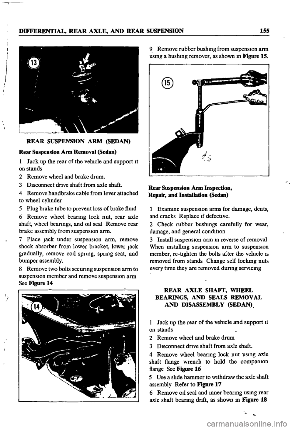
8
Remove
two
bolts
secunng
suspensIOn
arm
to
suspensIOn
member
and
remove
suspensIOn
arm
See
Figure
14
9
Remove
rubber
bushmg
from
suspensIon
arm
usmg
a
bushmg
remover
as
shown
In
Figure
15
@
Rear
SllSpension
Arm
Inspection
Repair
and
Installation
Sedan
1
Examme
suspensIOn
arms
for
damage
dents
and
cracks
Replace
tf
defectIve
2
Check
rubber
bushmgs
carefully
for
wear
damage
and
general
condItIon
3
Install
suspensIOn
arm
m
reverse
of
removal
When
Installmg
suspensIOn
arm
to
suspensIOn
member
re
tIghten
the
bolts
after
the
vehIcle
IS
removed
from
stands
Change
self
lockmg
nuts
every
tIme
they
are
removed
dunng
semcmg
REAR
AXLE
SHAFf
WHEEL
BEARINGS
AND
SEALS
REMOVAL
AND
DISASSEMBLY
SEDAN
1
Jack
up
the
rear
of
the
vehIcle
and
support
It
on
stands
2
Remove
wheel
and
brake
drum
3
DIsconnect
dnve
shaft
from
axle
shaft
4
Remove
wheel
bearmg
lock
nut
usmg
axle
shaft
flange
wrench
to
hold
the
companIOn
flange
See
Figure
16
5
Use
a
slIde
hammer
to
Withdraw
the
axle
shaft
assembly
Refer
to
Figure
17
6
Remove
011
seal
and
Inner
bearmg
usmg
rear
axle
shaft
bearmg
dnft
as
shown
In
Figure
18
Page 167 of 252

162
CHAPTER
TWELVE
14
Coat
the
front
bracket
pm
and
bushmg
and
shackle
pm
and
bushing
With
a
soap
solution
pnor
to
assembly
15
The
front
pm
secunng
nut
and
shock
ab
sorber
lower
end
securmg
nut
should
be
re
tightened
after
the
vehicle
is
sittmg
on
the
ground
16
Make
certaJn
the
shackle
bushmg
flange
is
clamped
evenly
on
both
Sides
SHOCK
ABSORBER
REMOVAL
INSPECTION
AND
INSTALLATION
WAGON
1
Jack
up
the
center
of
the
rear
axle
and
sup
port
th
e
axle
housmg
With
stands
2
Reinove
the
lower
end
of
the
rear
shock
absorber
from
spring
seat
3
Loosen
the
four
bolts
secunng
the
upper
bracket
to
body
Remove
shock
absorber
and
upper
bracket
4
Check
shock
absorber
for
leaks
and
cracks
Check
the
shaft
for
straighmess
Replace
1f
defective
5
Inspect
rubber
bushmgs
for
damage
cracks
and
general
condition
Replace
1f
defective
6
Install
the
shock
absorber
by
reversing
the
procedure
used
durmg
removal
DIFFERENTIAL
pICK
UP
The
dlfferenl1al
carner
IS
made
up
of
alum
mum
alloy
and
uses
a
hyp01d
bevel
gear
Proper
lubncatIon
IS
essenl1al
Check
and
replemsh
the
lubncant
every
3
000
mlles
Drain
and
refill
every
30
000
inlles
Figure
30
IS
a
cross
sectional
View
of
the
pick
up
dIfferential
Difterential
Removal
Pick
up
1
Jack
up
the
rear
wheels
and
support
vehicle
With
stands
2
DIsconnect
dnve
pmlOn
companlOn
flange
to
yoke
connectIon
3
Remove
rear
axles
as
descnbed
later
m
thIS
chapter
4
Remove
dlfferenl1al
gear
assembly
Difterential
Inspection
Pick
up
The
followmg
mspection
can
be
done
Without
disassembly
of
the
d1fferenl1al
If
abnormahties
or
damage
eXiSts
refer
further
serVice
and
reparr
to
your
dealer
1
Check
the
tooth
contact
pattern
WIth
lead
OXide
at
two
or
three
pomts
after
remoVlDg
rear
cover
Refer
to
FIgure
5
for
correct
contact
pattern
If
the
pattern
IS
faulty
disassembly
and
adJustment
of
the
dIfIerentialIs
required
2
Measure
backlash
between
dnve
gear
and
pmlOn
With
a
dial
mdlcator
Backlash
should
be
00051
to
0
0071
m
013
to
0
18mm
3
Rotate
the
gears
and
lISten
for
SignS
of
bear
mg
noise
4
Inspect
gear
teeth
for
SIgnS
of
damage
or
cracks
Difterential
Installation
Pick
up
Install
the
differential
by
reversmg
the
pro
cedures
used
dunng
removal
REAR
AXLE
AND
SUSPENSION
pICK
UP
The
rear
axle
IS
of
the
semi
floatIng
type
The
rear
wheels
use
tapered
roller
beanngs
Figure
31
IS
a
cross
sectional
view
of
the
rear
axle
REAR
SUSPENSION
TORQUE
TIGHTENING
SPECIFICATIONS
WAGON
Shock
absorber
upper
bracket
to
body
bolts
Shock
absorber
to
upper
bracket
lock
nuts
Shock
absorber
to
lower
bracket
lock
nuts
Rear
spnng
U
bolt
nuts
Shackle
nuts
Front
pm
nuts
Front
bracket
flxmg
nuts
Brake
dISC
to
rear
housmg
bolts
DifferentIal
carner
to
axle
housmg
bolt
Dnve
shaft
flange
nuts
11
to
18
ft
Ib
1
5
to
2
5
kg
m
12
to
16
ft
db
17
to
2
2
kg
m
25
to
33
ft
Ib
35
to
45
kg
m
43
to
47
ft
Ib
60
to
6
5
kg
m
32
to
36
ft
Ib
45
to
50
kg
m
32
to
36
ft
Ib
45
to
5
0
kg
m
13
to
17
ft
Ib
18
to
23
kg
m
20
to
28
ft
Ib
28
to
3
9
kg
m
14
to
16
ft
Ib
20
to
2
2
kg
m
20
to
28
ft
Ib
28
to
3
9
kg
m
Page 169 of 252
164
CHAPTER
TWELVE
Rear
Axle
Removal
Pick
up
1
Jack
up
the
vehicle
and
support
It
With
stands
2
Remove
wheels
and
brake
drum
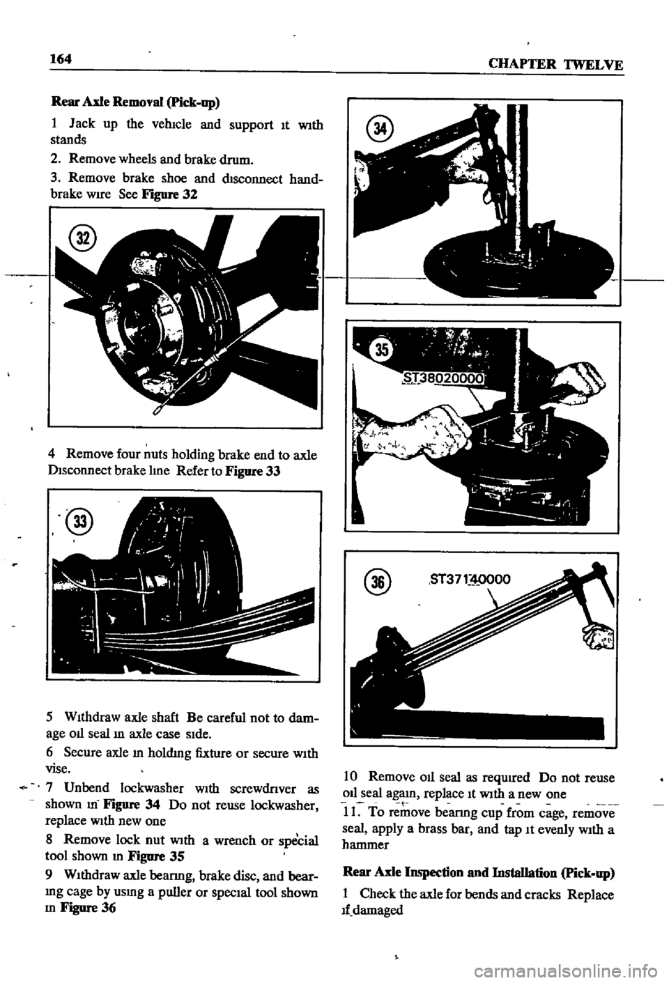
3
Remove
brake
shoe
and
chsconnect
hand
brake
WIre
See
Figure
32
4
Remove
four
nuts
holding
brake
end
to
axle
Disconnect
brake
hne
Refer
to
Figure
33
@
5
WIthdraw
axle
shaft
Be
careful
not
to
dam
age
01l
seal
ill
axle
case
SIde
6
Secure
axle
m
holdmg
fixture
or
secure
WIth
vise
7
Unbend
lockwasher
With
screwdnver
as
shown
m
FIgure
34
Do
not
reuse
lockwasher
replace
With
new
one
8
Remove
lock
nut
With
a
wrench
or
special
tool
shown
m
Figure
35
9
WIthdraw
axle
beanng
brake
disc
and
bear
mg
cage
by
usmg
a
puller
or
SpecIal
tool
shown
m
Figure
36
@
10
Remove
011
seal
as
required
Do
not
reuse
011
seal
agaJn
replace
It
With
a
new
one
t
11
To
remove
bearmg
cup
from
cage
remove
seal
apply
a
brass
bar
and
tap
It
evenly
With
a
hammer
Rear
Axle
Inspection
nnd
Installation
Pick
up
1
Check
the
axle
for
bends
and
cracks
Replace
1f
damaged