1968 DATSUN 510 ECU
[x] Cancel search: ECUPage 26 of 252

ENGINE
AND
IGNITION
TUNE
UP
21
many
types
of
test
eqUipment
and
may
be
used
as
a
gUide
If
the
manufacturer
s
mstructioQs
are
not
aVailable
Connections
shown
in
Figure
1
are
as
follows
1
Voltmeter
a
PosItive
lead
to
resistor
side
of
COli
b
Negative
1
ead
to
ground
2
Tlmmg
Light
a
PosItive
lead
to
posItive
battery
termmal
b
Tngger
lead
to
number
1
spark
plug
c
Negative
lead
to
ground
3
Tachometer
a
PosItive
lead
to
dlstnbutor
Side
of
coil
b
Negative
lead
to
ground
4
Dwell
Meter
a
PosItive
lead
to
dlstnbutor
Side
of
COlI
b
Negative
lead
to
ground
BAlTERY
INSPECTION
AND
SERVICE
1
Check
the
level
of
the
electrolyte
m
battery
cells
If
necessary
replemsh
with
distilled
water
Do
not
overfill
2
Measure
the
speCific
gravity
of
the
battery
electrolyte
Refer
to
the
followmg
table
2
Use
the
proper
size
socket
and
wrench
to
remove
spark
plugs
from
the
cyhnder
head
Make
certam
that
the
gaskets
are
removed
from
the
spark
plug
holes
3
Wipe
off
the
msulator
With
a
clean
rag
to
remove
grease
and
dirt
4
Carefully
mspect
the
msulator
and
body
of
each
plug
for
signs
of
cracks
or
chips
Replace
If
faulty
5
Inspect
spark
plug
threads
and
electrodes
for
damage
or
excessive
wear
Replace
as
requrred
Figure
2
shows
the
cond1t
J
on
of
normal
and
de
fectIVe
spark
plugs
along
with
an
explanation
of
the
causes
of
the
abnormal
conditions
6
If
the
spark
plugs
are
still
serviceable
clean
them
thoroughly
With
a
stiff
brush
or
preferably
With
a
sand
blasting
type
of
cleaner
7
File
the
center
electrode
so
that
It
has
a
fiat
surface
8
File
the
surfaces
of
the
outer
electrode
so
that
all
surfaces
are
fiat
and
smooth
9
Usmg
a
feeler
gauge
adjust
clearance
be
tween
the
electrodes
to
0
031
to
0
035
m
0
8
to
0
9mm
as
shown
m
Figure
3
Full
Charge
Value
CD
68
degrees
F
PermiSSIble
Value
20
degrees
C
3
Frigid
chmates
Tropical
chmates
Other
climates
Over
1
22
Over
118
Over
1
20
128
123
126
3
Clean
top
of
battery
and
termmals
With
a
solutIOn
of
bakmg
soda
and
water
Rmse
off
and
dry
thoroughly
Top
of
battery
must
be
clean
to
prevent
current
leakage
between
termmal
and
from
pOSitive
termmal
to
hold
down
clamp
Pro
longed
accumulatIOn
of
aCid
and
dirt
on
top
of
battery
may
cause
blIstenng
of
the
matenal
cov
enng
on
the
connector
straps
and
detenoration
of
the
straps
themselves
4
Tighten
the
cable
connectors
to
the
termmal
securely
5
Coat
the
termmals
lIghtly
With
petrolatum
to
protect
them
from
corrosion
SPARK
PLUGS
INSPECTION
AND
SERVICE
1
Remove
spark
plug
WIres
Mark
them
to
fi
sure
correct
replacement
J
J
I
I
j
j
10
Remstall
spark
plugs
Make
certam
to
use
a
new
gasket
for
each
plug
Use
a
torque
wrench
to
tighten
spark
plugs
from
11
0
to
150
ft
lb
1
5
to
2
0
kg
m
11
Remstall
WIres
DISTRIBUTOR
INSPECTION
AND
SERVICE
Dependmg
on
the
model
year
velucles
have
a
smgle
pomt
or
a
dual
pomt
dlstnbutor
system
Page 28 of 252

ENGINE
AND
IGNITION
TUNE
UP
23
CD
ADJUSTING
SCREWS
FOR
THE
POSITION
OF
RETARDED
BREAKER
POINT
r
A
O
S
8
6
C
0
18
2
6
10
14
contact
pomt
assembly
from
the
dIStnbutor
and
clean
or
replace
the
pomts
Use
a
pomt
file
to
clean
the
contacts
Do
not
attempt
to
remove
all
roughness
Apply
a
trace
of
beanng
lubncant
to
the
breaker
cam
5
Once
the
pomts
have
been
cleaned
or
re
placed
mstall
the
assembly
m
the
dlstnbutor
Make
certam
to
reconnect
wires
6
Adjust
the
pomt
gap
Figure
S
With
the
use
of
a
screwdnver
and
gap
gauge
Make
certaIn
the
rubbmg
arm
on
the
contact
assembly
IS
rest
mg
on
the
hIgh
pomt
of
the
carn
Pomt
gap
should
be
adjusted
to
0
0177
through
00217
m
0
45
to
0
55mm
CD
7
Check
condenser
capacItance
for
a
readmg
of
o
22
through
0
24
mIcrofarads
Replace
If
de
fectIve
As
a
matter
of
good
practIce
the
con
r
denser
should
be
replaced
whenever
the
pomts
are
replaced
8
Inspect
the
InSulatIon
on
all
WIres
WIthIn
the
dIStributor
Replace
If
defectIve
9
Inspect
the
WIre
towers
atop
the
dIStnbutor
cap
for
SignS
of
dIrt
or
corrosIOn
A
pencIl
wIth
fine
emery
cloth
wrapped
around
the
erasl
e
end
can
be
used
to
clean
and
burnISh
the
metal
sur
faces
Make
certam
to
blowout
any
dust
10
Replace
the
rotor
md
the
cap
on
the
dIs
tnbutor
and
secure
the
two
hold
down
clamps
FI
ly
msert
IgrntIon
WIres
mto
proper
towers
ill
cap
IGNITION
TIMING
IgmtIon
tIDlIDg
is
adjusted
with
the
engine
runnmg
Use
a
strobOSCOpIC
timing
hght
and
pro
ceed
as
follows
1
Make
certam
that
spl
l
k
plug
gaps
and
dIs
tnbutor
contact
pomts
are
accurately
set
2
DISconnect
the
vacuum
hne
from
the
carbu
retor
at
the
dIstrIbutor
Plug
the
end
of
the
vacuum
hne
wIth
tape
or
a
wooden
stopper
3
Hook
up
the
trmmg
light
per
mstructIons
4
Hook
up
tachometer
per
mstructions
5
The
tImmg
marles
are
located
on
the
front
edge
of
the
crankshaft
pulley
The
grooves
are
graduated
m
5
degree
mcrements
The
top
dead
center
mark
S
located
to
the
extreme
left
hand
sIde
of
the
engme
as
vIewed
from
the
front
A
statIOnary
pomter
S
connected
to
the
cylinder
Page 33 of 252
28
CHAPTER
FIVE
011
gallery
supphes
011
to
the
crankshaft
mam
beanngs
Dnlled
passages
m
the
crankshaft
direct
oil
from
the
mam
bearings
to
the
con
nectmg
rod
beanngs
011
mJected
from
jet
holes
in
the
connectIng
rods
IS
directed
to
the
cylmder
walls
and
piston
pins
0U
dlstnbuted
from
the
mam
gallery
enters
the
cham
tensioner
The
pad
IS
held
against
the
cham
by
011
pressure
and
spnng
tension
The
tmung
chain
receives
011
through
the
Jet
located
near
It
LubncatIon
IS
supphed
to
the
cyhnder
head
mam
011
gallery
through
the
crankshaft
center
beanngs
Camshaft
beanngs
on
the
cyhnder
head
are
fed
directly
from
the
cyhnder
head
mam
gallery
The
rocker
arms
and
valves
are
lubncated
intermittently
by
the
camshaft
011
gallery
and
the
small
channel
at
the
base
CIrcle
portIon
of
each
cam
OllIS
supphed
to
the
cam
shaft
011
gallery
through
the
No
2
and
No
3
camshaft
bearings
OIL
PUMP
The
011
pump
IS
mstalled
m
the
bottom
of
the
front
cover
as
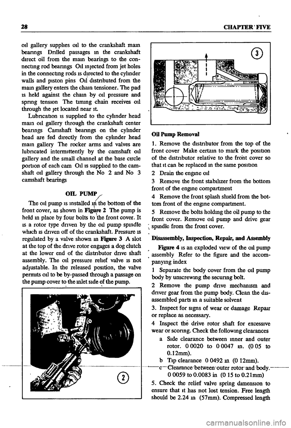
shown
in
2
The
pump
is
held
m
place
by
four
bolts
to
the
front
cover
It
IS
a
rotor
type
dnven
by
the
011
pump
spmdle
whIch
IS
dnven
off
of
the
crankshaft
Pressure
IS
regulated
by
a
valve
shown
m
Figure
3
A
slot
at
the
top
of
the
dnve
rotor
engages
a
dog
clutch
at
the
lower
end
of
the
distnbutor
dnve
shaft
assembly
The
011
pressure
rehef
valve
IS
not
adjustable
In
the
released
pOSition
the
valve
pernnts
011
to
be
by
passed
through
a
passage
on
the
pump
cover
to
the
mlet
Side
of
the
pump
CD
CD
Oil
Pump
Removal
1
Remove
the
dIStnbutor
from
the
top
of
the
front
cover
Make
certam
to
mark
the
posItIon
of
the
dtstnbutor
relative
to
the
front
cover
so
that
It
can
be
replaced
m
the
same
posItIon
2
Drain
the
engme
od
3
Remove
the
front
stabIhzer
from
the
bottom
front
of
the
engme
compartment
4
Remove
the
front
splash
shIeld
from
the
bot
tom
front
of
the
engine
compartment
5
Remove
the
bolts
holdmg
the
oil
pump
to
the
front
cover
Remove
011
pump
and
drive
gear
spmdle
from
the
front
cover
Disassembly
Inspection
Repair
and
Assembly
Figure
4
IS
an
exploded
VIew
of
the
011
pump
assembly
Refer
to
the
figure
and
the
accom
panymg
index
1
Separate
the
body
cover
from
the
011
pump
body
by
unscreWIng
the
secunng
bolt
2
Remove
the
pump
dnve
mechamsm
and
dnver
gear
from
the
pump
body
Clean
the
dIS
assembled
parts
m
a
suitable
solvent
3
Inspect
for
Signs
of
wear
or
damage
Reparr
or
replace
as
necessary
4
Inspect
the
drive
rotor
shaft
for
excessive
wear
or
sconng
Check
the
followmg
clearances
a
Side
clearance
between
mner
and
outer
rotor
00020
to
00047
m
005
to
0
12mm
b
Tip
clearance
0
0492
m
0
12mm
c
elearance
between
outer
rotor
and
body
00059
to
0
0083
in
015
to
0
21mm
5
Check
the
relief
valve
spring
dtmenslOn
to
ensure
that
It
has
not
lost
tension
Free
length
should
be
2
24
m
57mm
Compressed
length
Page 43 of 252
38
CHAPTER
SIX
EMISSION
CONTROL
DEVICES
All
Datsuns
have
a
sealed
type
of
crankcase
emISSion
control
device
and
an
exhaust
emISsion
control
deVice
Models
sold
m
Cahfornla
smce
1970
also
have
an
evaporative
emisSion
control
deVice
An
rmportant
part
of
the
exhaust
control
device
is
the
air
pump
located
at
the
bottom
left
hand
side
of
the
engme
It
IS
dnven
by
a
belt
off
of
the
crankshaft
pulley
and
supphes
air
to
the
exhaust
system
In
1972
an
electric
blower
in
corporated
m
the
air
cleaner
replaced
the
mechanical
pumI
ENGINE
REMOVAL
Expenence
has
shown
It
IS
easier
to
remove
the
engine
and
the
transmission
as
a
smgle
UnIt
than
to
remove
the
engme
alone
Once
the
en
gine
and
transmiSSIon
are
out
of
the
vehIcle
the
tranSmIssion
can
be
detached
from
the
engme
To
remove
the
engme
transmISsion
proceed
as
follows
1
Scribe
ahgnment
marks
on
the
hood
around
the
hmges
ThIS
will
make
remstallatlon
eaSIer
2
Remove
the
two
bolts
that
secure
each
hInge
and
remove
the
hood
It
is
not
necessary
to
re
move
the
hood
support
from
the
engme
firewall
3
DISconnect
the
lower
radIator
hose
from
the
right
hand
SIde
of
the
engine
and
at
the
bottom
of
the
radIator
ThIS
will
pernnt
coolant
to
dram
from
the
engme
and
the
radIator
4
Remove
the
draIn
plugs
from
the
engine
pan
and
translIDSsIon
and
completely
dram
lubn
cants
Into
suitable
contamers
5
DISconnect
the
battery
cables
from
the
bat
tery
loosen
the
two
hold
down
clamps
and
re
move
the
battery
NOTE
The
location
and
number
of
hoses
to
be
removed
from
the
air
cleaner
varies
from
model
to
model
It
IS
normally
easier
to
remove
the
hoses
from
the
sources
rather
than
try
to
dISconnect
them
from
yndemeath
the
air
cleaner
The
1972
model
Will
requlre
dlsconnectlOn
of
the
electrica1
cirCUit
In
the
air
cleaner
system
wing
nut
from
the
top
of
the
air
cleaner
and
remove
the
aIr
cleaner
7
DIsconnect
the
upper
radiator
hose
from
the
radiator
and
the
thermostat
housmg
Remove
the
hose
8
Disconnect
the
two
heater
hoses
from
the
nght
hand
side
of
the
engme
TIe
these
bac
so
they
won
t
interfere
with
removal
of
the
engme
9
Remove
the
radIator
grille
by
unscrewing
all
mountmg
screws
10
Remove
the
four
mounting
screws
holding
the
fan
shield
to
the
backside
of
the
radiator
11
Remove
the
four
mountmg
bolts
holdIng
the
radiator
In
place
In
automatic
tranSmISsion
models
dISconnect
the
two
transnnsslOn
oIl
cooler
lInes
from
the
bottom
of
the
radiator
Pull
the
radiator
straight
up
to
remove
Remove
the
fan
shield
12
Loosen
the
adjustment
and
mounting
bolts
from
the
retamIng
brackets
on
the
alternator
and
air
pump
If
so
eqwpped
The
alternator
is
lo
cated
at
the
bottom
nght
hand
Side
of
the
engme
and
the
air
pump
on
the
lower
left
hand
Side
13
Loosen
tenSIon
on
the
two
dnve
belts
re
move
the
belts
from
the
alternator
and
air
pump
and
then
from
the
fan
pulleys
14
Remove
the
bolts
holdIng
the
fan
and
pulley
to
the
water
pump
assembly
and
remove
the
fan
and
pulley
15
DISconnect
the
fuel
hne
from
the
fuel
pump
16
DIsco
ect
accelerator
control
linkage
and
choke
WIre
at
the
carburetor
17
Disconnect
the
wiring
from
the
starter
motor
alternator
Ignition
coIl
oIl
pressure
switch
and
temperature
transmItting
unit
NOTE
The
following
steps
are
per
formed
from
under
the
car
lack
up
the
front
of
the
car
and
position
stands
under
the
front
support
points
to
proVide
working
room
under
the
vehicle
WARNING
Never
climb
under
a
vehicle
that
is
supported
by
the
lack
only
If
stands
are
not
avflllable
sturdy
wooden
blocks
can
be
U3ed
6
Disconnect
all
hoses
that
lead
to
the
air
cleaner
remove
two
bolts
that
hold
the
air
cleaner
to
its
mountmg
bracket
unscrew
the
18
Remove
two
bolts
holdIng
the
clutch
operat
Ing
cylInder
to
the
flywheel
hOUSIng
shown
m
Page 44 of 252
ENGINE
39
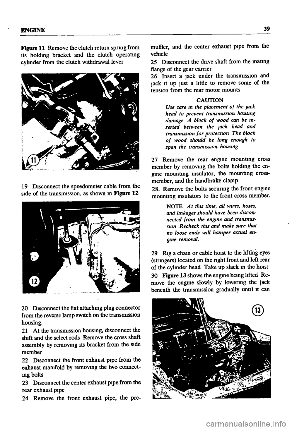
Figure
11
Remove
the
clutch
return
spnng
from
Its
holdmg
bracket
and
the
clutch
operatmg
cylmder
from
the
clutch
withdrawal
lever
19
Disconnect
the
speedometer
cable
from
the
side
of
the
transnnsslOn
as
shown
m
Figure
12
20
Disconnect
the
flat
attachmg
plug
connector
from
the
reverse
lamp
sWitch
on
the
translDlSSlon
housing
21
At
the
transnnsslOn
housmg
disconnect
the
shIft
and
the
select
rods
Remove
the
cross
shaft
assembly
by
remOVIng
Its
bracket
from
the
Side
member
22
DISconnect
the
front
exhaust
pipe
from
the
exhaust
manIfold
by
remoVing
the
two
connect
mg
bolts
23
Disconnect
the
center
exhaust
pipe
from
the
rear
exhaust
pipe
24
Remove
the
front
exhaust
pipe
the
pre
muffler
and
the
center
exhaust
pipe
from
the
vehicle
25
Disconnect
the
dnve
shaft
from
the
matIng
flange
of
the
gear
carner
26
Insert
a
Jack
under
the
transmiSSIOn
and
jack
It
up
Just
a
little
to
remove
some
of
the
tension
from
the
rear
motor
mounts
CAUTION
Use
care
m
the
placement
of
the
lack
head
to
prevent
transmiSSIOn
housmg
damage
A
block
of
wood
can
be
m
serted
between
the
Jack
head
and
transmISSIOn
for
protection
The
block
of
wood
should
be
long
enough
to
span
the
transmiSSion
housmg
27
Remove
the
rear
engine
mountIng
cross
member
by
remoVing
the
bolts
holdmg
the
en
gine
mountIng
msulator
the
mountIng
cross
member
and
the
handbrake
clamp
28
Remove
the
bolts
secunng
the
front
engine
mountmg
msulators
to
the
front
cross
member
NOTE
At
thiS
time
all
Wires
hoses
and
lmkages
should
have
been
dIScon
nected
from
the
engme
and
transmIS
sIOn
Recheck
thiS
and
make
sure
that
no
loose
ends
Will
hamper
actual
en
gme
removal
29
RIg
a
cham
or
cable
hOist
to
the
lifting
eyes
stnngers
located
on
the
nght
front
and
left
rear
of
the
cylmder
head
Take
up
slack
m
the
hOist
30
Figure
13
shows
the
engme
bemg
lifted
Re
move
the
engine
slowly
by
lowenng
the
jack
beneath
the
transnnssion
gradually
until
It
can
@
Page 47 of 252
4Z
CHAPTER
SIX
the
adJustmg
bar
mto
the
mountmg
flange
of
the
arr
pump
2
Remove
the
bolt
lInking
the
arr
pump
to
the
mountmg
bracket
and
remove
pump
3
The
bracket
has
four
bolts
to
the
engme
the
adJustmg
bar
mounts
on
the
front
cover
WIth
two
bolts
Remove
these
to
free
the
front
cover
Water
Pump
Removal
I
Remove
the
bolts
and
lockwashers
Jommg
the
water
pump
to
the
front
cover
The
number
of
bolts
vanes
from
year
to
year
due
to
pump
aesign
clianges
Remove
water
pump
Fuel
Pump
Removal
I
Remove
the
two
nuts
and
lockwashers
secur
mg
fuel
pump
to
the
engIne
and
remove
pump
Rocker
Arm
COYer
Removal
I
Remove
SIX
bolts
holdmg
rocker
arm
cover
to
head
and
lIft
off
cover
Intake
and
Exhaust
Manifold
Removal
I
Remove
eleven
nuts
and
lockwashers
that
secure
the
mtake
and
exhaust
manIfolds
2
Remove
mtake
and
exhaust
manIfolds
as
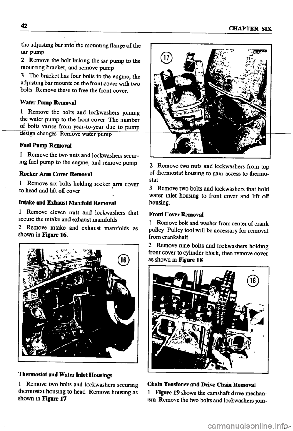
shown
in
Figure
16
Thermostat
and
Water
Inlet
Housings
1
Remove
two
bolts
and
lockwashers
secunng
thermostat
housmg
to
head
Remove
housmg
as
shown
m
Figure
17
@
2
Remove
two
nuts
and
lockwashers
from
top
of
thermostat
housmg
to
gam
access
to
thermo
stat
3
Remove
two
bolts
and
lockwashers
that
hold
water
mlet
housmg
to
front
cover
and
lIft
off
housing
Front
Cover
Removal
1
Remove
bolt
and
washer
from
center
of
crank
pulley
Pulley
tool
Will
be
necessary
for
removal
from
crankshaft
2
Remove
nme
bolts
and
lockwashers
holdmg
front
cover
to
cylInder
block
then
remove
cover
as
shown
m
Figure
18
@
Chain
Tensioner
and
Drive
Chain
Removal
I
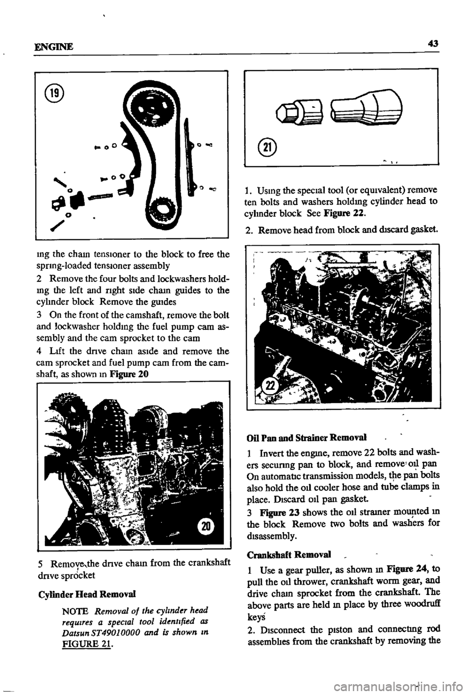
Figure
19
shows
the
camshaft
dnve
mechan
Ism
Remove
the
two
bolts
and
lockwashers
010
Page 48 of 252
ENGINE
43
@
0
00
o
mg
the
cham
tenslOner
to
the
block
to
free
the
sprIng
loaded
tenslOner
assembly
2
Remove
the
four
bolts
and
lockwashers
hold
mg
the
left
and
rIght
sIde
cham
guides
to
the
cylmder
block
Remove
the
guIdes
3
On
the
front
of
the
camshaft
remove
the
bolt
and
lockwasher
holdIng
the
fuel
pump
cam
as
sembly
and
the
eam
sprocket
to
the
eam
4
LIft
the
drIve
chaIn
asIde
and
remove
the
earn
sprocket
and
fuel
pump
cam
from
the
cam
shaft
as
shown
In
Figure
20
5
Remove
the
dnve
cham
from
the
crankshaft
drIve
spr6cket
Cylinder
Head
Removal
NOTE
Removal
of
the
cylinder
head
requires
a
special
tool
identified
as
DatsunST49010000
and
is
shown
In
FIGURE
21
@
I
USIng
the
specIal
tool
or
eqUIvalent
remove
ten
bolts
and
washers
holdIng
cylinder
head
to
cyhnder
block
See
Figure
22
2
Remove
head
from
block
and
dtscard
gasket
Oil
Pan
and
Strainer
Removal
I
Invert
the
engme
remove
22
bolts
and
wash
ers
secunng
pan
to
block
and
remove
011
pan
On
automatIc
transmission
models
tpe
pan
bolts
also
hold
the
oIl
cooler
hose
and
tube
clamps
in
place
DISCard
011
pan
gasket
3
Figure
23
shows
the
oIl
stramer
mOlJ
lted
m
the
block
Remove
two
bolts
and
washers
for
dISassembly
Crankshaft
Removal
I
Use
a
gear
puller
as
shown
III
Figure
24
to
pull
the
oIl
thrower
crankshaft
worm
gear
and
drive
cham
sprocket
from
the
crankshaft
The
above
parts
are
held
In
place
by
three
woodruff
keyS
2
DISconnect
the
pIston
and
connectrng
rod
assemblIes
from
the
crankshaft
by
removing
the
Page 49 of 252
44
CHAPTER
SIX
@
@
eight
connecting
rod
bolts
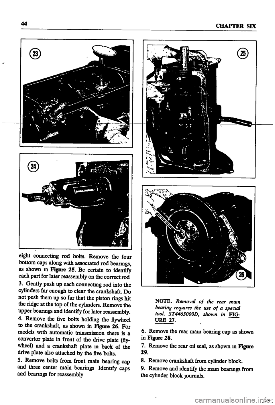
Remove
the
four
bottom
caps
along
with
assoc1ated
rod
beanngs
as
shown
m
Figure
25
Be
certain
to
identify
each
part
for
later
reassembly
on
the
correct
rod
3
Gently
push
up
each
connecting
rod
into
the
cylinders
far
enough
to
clear
the
crankshaft
Do
not
push
them
up
so
far
that
the
piston
rings
hit
the
ridge
at
the
top
of
the
cyImders
Remove
the
upper
beanngs
and
identify
for
later
reassembly
4
Remove
the
five
bolts
holding
the
flywheel
to
the
crankshaft
as
shown
in
Figure
26
For
models
Wlth
automatic
transmisslOn
there
is
a
convertor
plate
in
front
of
the
drive
plate
fly
wheel
and
a
crankshaft
plate
m
back
of
the
drive
plate
also
attached
by
the
five
bolts
5
Remove
bolts
from
front
main
bearing
cap
and
three
center
main
bearings
Identtfy
caps
and
beanngs
for
reassembly
@
NOTE
Removal
of
the
rear
mam
bearing
requires
the
use
of
a
specuzl
tool
ST4463000D
shown
in
f
Q
URE
27
6
Remove
the
rear
mam
bearing
cap
as
shown
in
Figure
28
7
Remove
the
rear
011
seal
as
shown
m
Figure
29
8
Remove
crankshaft
from
cylinder
block
9
Remove
and
1dentify
the
mam
beanngs
from
the
cyhnder
block
JOurnals