Page 185 of 629
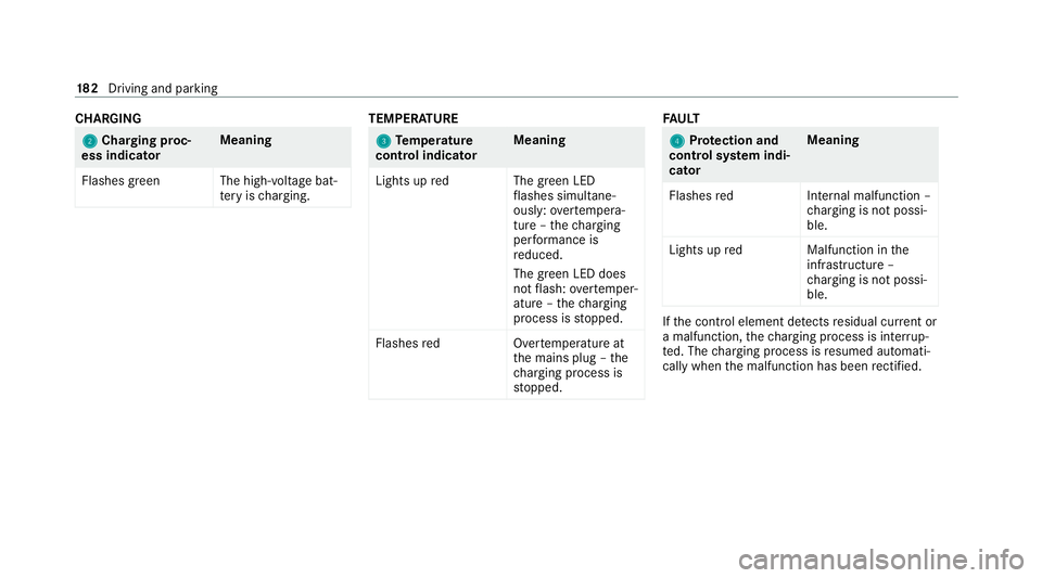
CHA
RGING 2 2
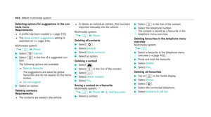
Cha rging proc‐
ess indicator Meaning
Flashes green The high- voltage bat‐
te ry isch arging. TEMPER
ATURE 3
3
Temp erature
control indica torMeaning
Lights up redT he green LED
fl ashes simul tane‐
ously: overtemp era‐
ture – thech arging
per form ance is
re duced.
The green LED does
not flash: overtemp er‐
ature – thech arging
process is stopped.
Flashes redO vertemperature at
th e mains plug – the
ch arging process is
st opped. FA
ULT 4 4
Protection and
control sy stem indi‐
cator Meaning
Flashes redI nternal malfunction –
ch arging is not possi‐
ble.
Lights up redM alfunction inthe
inf rastru cture –
ch arging is not possi‐
ble. If
th e control element de tects residual cur rent or
a malfunction, thech arging process is inter rup‐
te d. The charging process is resumed automati‐
cally when the malfunction has been rectified. 18 2
Driving and pa rking
Page 186 of 629

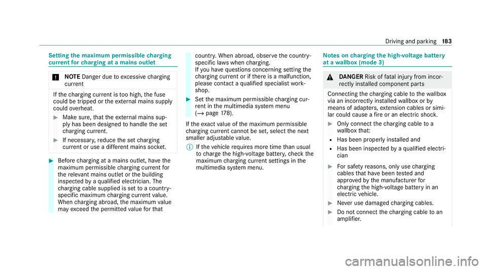
Setting
the maximum permissible charging
cur rent forch arging at a mains outlet *
NO
TEDanger due toexcessive charging
cur rent If
th ech arging cur rent is too high, the fuse
could be tripped or theex tern al mains supply
could overheat. #
Make sure, that theex tern al mains sup‐
ply has been designed tohandle the set
ch arging cur rent. #
If necessa ry,re duce the set charging
cur rent or use a di fferent mains soc ket. #
Before charging at a mains outlet, ha vethe
maximum permissible charging cur rent for
th ere leva nt mains outlet or the building
inspected byaqu alified electrician. The
ch arging cable supplied is set toa countr y-
specific maximum charging cur rent value.
When charging abroad, the maximum value
may exceed the permitted value forth at countr
y.When abroad, obser vethe count ry-
specific la wswhen charging.
If yo u ha vequestions concerning setting the
ch arging cur rent or if there is a malfunction,
please conta ct aqualified specialist work‐
shop. #
Set the maximum permissible charging cur‐
re nt in the multimedia sy stem menu
(/ page 178).
If th eex act value of the maximum permissible
ch arging cur rent cannot be set, select the next
smaller adjus table value.
% Ifth eve hicle requ ires more time than usual
to charge the high-voltage batter y,ch eck the
maximum charging cur rent settings in the
multimedia sy stem menu. Note
s oncharging the high-voltage bat tery
at a wallbox (mode 3) &
DANG ER Risk of fata l injury from incor‐
re ctly ins talled component parts
Connecting thech arging cable tothewa llbox
via an incor rectly ins talled wallbox or by
means of adapt ers,extension cables or simi‐
lar could cause a fire or an electric shoc k. #
Only connect thech arging cable to a
wa llbox that:
R Has been proper ly installed and
R Has been inspec tedby aqu alified electri‐
cian #
For saf etyre asons, on lyuse charging
cables that ha vebeen tested and
appr ovedby the manufacturer for
ch arging the high-voltage battery in an
electric vehicle. #
Never use dama gedch arging cables. #
Do not connect thech arging cable toan
amplifier. Driving and parking
18 3
Page 187 of 629

#
Do not extend thech arging cable. #
Do not use adap ters. #
Obser vethe saf ety no tes in the operat‐
ing instructions forth ewa llbox. If
ch arging at a wallbox without pre-in stalled
cable, use the optionally available charging cable
fo rwa llbox and charging station (mode 3). The
ch arging cable is stowed in a bag in the boot.
Only use charging cables that ha vebeen tested
and appr ovedby the manufacturer forch arging
th e high-voltage battery in an electric vehicle. Note
s oncharging the high-voltage bat tery
at a charging station (mode 3/4) &
DANG ER Risk of fata l injury from dam‐
aged component parts
If, at a charging station, you use a damaged
cable, adap ter,ex tension cable or similar to
connect theve hicle toach arging station this
may cause a fire or an electric shoc k. #
Atcharging stations with a pre-ins talled
ch arging cable:
R A visual check of thech arging point
fo r obvious faults, such as massive
damage tothe housing or charging
cable. #
Atcharging stations without a pre-
ins talled charging cable:
R For saf etyre asons, on lyuse charg‐
ing cables that ha vebeen tested
and appr oved bythe manufacturer
fo rch arging the high-voltage battery
in an electric vehicle.
R Never use dama gedch arging
cables.
R Do not extend thech arging cable.
R Do not use adap ters. #
Alw ays obser vethe saf ety no tes on the
ch arging station. Most
charging stations must be activated before
th ech arging process, e.g. using an RFID card.
Obse rveth e on-site operator's instructions for
th ech arging station. St
arting thech arging process &
DANG ER Risk of fata l injury when charg‐
ing with a damaged soc ket
The charging process in volves high voltage. If
th ech arging cable, vehicle soc ket or mains
soc ket is dama ged, you could suf fer an elec‐
tric shoc k. #
Only use an undamaged charging cable. #
Avoid mechanical damage, e.g. caused
by squashing, shearing or driving over
th e cable. #
Have a damaged vehicle soc ket
re placed at a qualified specialist work‐
shop as soon as possible. #
Never connect thech arging cable to a
damaged vehicle soc ket. *
NO
TEOver voltage in the mains supply
can damage theve hicle. The
vehicle is therefore equipped with a
device which pr otects it from overvoltage in 184
Driving and pa rking
Page 188 of 629

th
e mains supply. This pr otection device may
be triggered during se vere thunder storms,
fo rex ample, and may cause the building pro‐
te ction sy stem totrip or may inter rupt the
ch arging process. These functions help to
pr otect theve hicle.
Af terth e building pr otection sy stem has
been switched on again, thech arging proc‐
ess resumes automatically.
Fo llowing an inter ruption in the po wer supp ly
without the building pr otection sy stem being
tripped, it may take up to10 minutes for
ch arging toresume automatically. *
NO
TEHeat generated bythech arging
cable and charging cable connec tor During
thech arging process, thech arging
cable and charging cable connec tor may heat
up within permissible limit values. The permissible limit
values are obser ved
pr ov ided that:
R The mains po wer supply equipment and
th ech arging cable are not damaged.
R The instructions for handling thech arging
cable and controls on thech arging cable
ha ve been follo we d. #
Ifth ech arging cable or charging cable
connec tor becomes too hot, ha vethe
po we r supp lyequipment of the mains
supply checked. *
NO
TEDama ged or dirty vehicle soc ket #
Alw ayske ep the soc ket co ver and the
soc ketflap closed when there is no
ch arging cable connec ted. This pr otects
th eve hicle soc ket from di rtand dam‐
age. #
Make sure that the soc ket co ver is
closed properly before closing the
soc ketflap. This can otherwise result in damage which may pr
eventthe soc ket
fl ap from being opened again. Re
quirements:
R The transmission is in position j.
R The vehicle is unloc ked.
R The drive sy stem has not been star ted.
R The charging cable is not taut.
% Depending on the national version, theve hi‐
cle is equipped with one of thefo llowing
ve hicle soc kets. Driving and pa
rking 18 5
Page 189 of 629

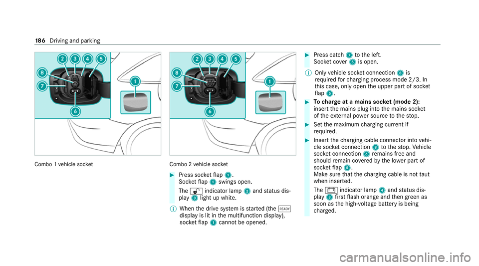
Combo 1
vehicle soc ket Combo 2
vehicle soc ket #
Press soc ketflap 1.
Soc ketflap 1 swings open.
The % indicator lamp 2and status dis‐
play 3light up white.
% When the drive sy stem is star ted (the õ
display is lit in the multifunction display),
soc ketflap 1 cannot be opened. #
Press cat ch7 tothe left.
Soc ket co ver5 is open.
% Only vehicle soc ket connection 8is
re qu ired forch arging process mode 2/3. In
th is case, only open the upper part of soc ket
fl ap 5. #
Tocharge at a mains soc ket (mode 2):
insert the mains plug into the mains soc ket
of theex tern al po wer source tothestop. #
Set the maximum charging cur rent if
re qu ired. #
Insert thech arging cable connec tor into vehi‐
cle soc ket connection 8tothestop. Vehicle
soc ket connection 6remains free and
should remain co veredby the lo wer part of
soc ketflap 5.
Make sure that thech arging cable is not taut
when inser ted.
The # indicator lamp 4and status dis‐
play 3firs tflash orange and then green as
soon as the high-voltage battery is being
ch arge d. 18 6
Driving and pa rking
Page 190 of 629

#
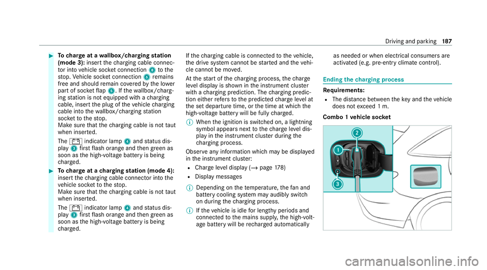
Tocharge at a wallbox/charging station
(mode 3): insertthech arging cable connec‐
to r into vehicle soc ket connection 8tothe
st op. Vehicle soc ket connection 6remains
free and should remain co veredby the lo wer
part of soc ketflap 5. If thewa llbox/ charg‐
ing station is not equipped with a charging
cable, insert the plug of theve hicle charging
cable into thewa llbox/ charging station
soc ketto thestop.
Make sure that thech arging cable is not taut
when inser ted.
The # indicator lamp 4and status dis‐
play 3firs tflash orange and then green as
soon as the high-voltage battery is being
ch arge d. #
Tocharge at a charging station (mode 4):
insert thech arging cable connec tor into the
ve hicle soc ketto thestop.
Make sure that thech arging cable is not taut
when inser ted.
The # indicator lamp 4and status dis‐
play 3firs tflash orange and then green as
soon as the high-voltage battery is being
ch arge d. If
th ech arging cable is connec tedto theve hicle,
th e drive sy stem cann otbe star ted and theve hi‐
cle cannot be mo ved.
At thest art of thech arging process, thech arge
le ve l display is shown in the instrument clus ter
with a charging prediction. The charging predic‐
tion either refers to the predicted charge leve l at
th e set departure time, or the time at which the
high-voltage battery will be fully charge d.
% When the ignition is switched on, a lightning
symbol appears next tothech arge leve l dis‐
play in the instrument clus ter during the
ch arging process.
Obse rve any information which may be displa yed
in the instrument clus ter:
R Char geleve l display (/ page178)
R Displ aymessa ges
% Depending on thete mp erature, thefa n and
battery cooling sy stem may audibly switch
on during thech arging process.
% Ifth eve hicle is idle for lengt hyperiods and
connec tedto the mains suppl y,the high-volt‐
age battery will be rech arge d automatically as needed or when elect
rical consumers are
acti vated (e.g. pre-entry climate control). Ending
thech arging process Re
quirements:
R The dis tance between theke y and theve hicle
does not exceed 1 m.
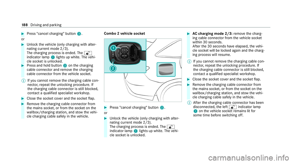
Combo 1 vehicle soc ket Driving and pa
rking 187
Page 191 of 629

#
Press "cancel charging" button 3.
or #
Unlock theve hicle (only charging with alter‐
nating cur rent mode 2/3).
The charging process is ended. The %
indicator lamp 1lights up white. The vehi‐
cle soc ket is unloc ked. #
Press and hold button 2onthech arging
cable connec tor and remo vethech arging
cable connec tor from theve hicle soc ket.
% Ifyo u cannot remo vethech arging cable con‐
nec tor,re peat the unlocking procedure. If
th ech arging cable connec tor is still bloc ked,
con tact a qualified specialist workshop. #
Close the soc ket co ver and the soc ketflap. #
Remo vethech arging cable connec tor from
th e mains soc ket, or from the soc ket on the
wa llbox/ charging station, and stow theve hi‐
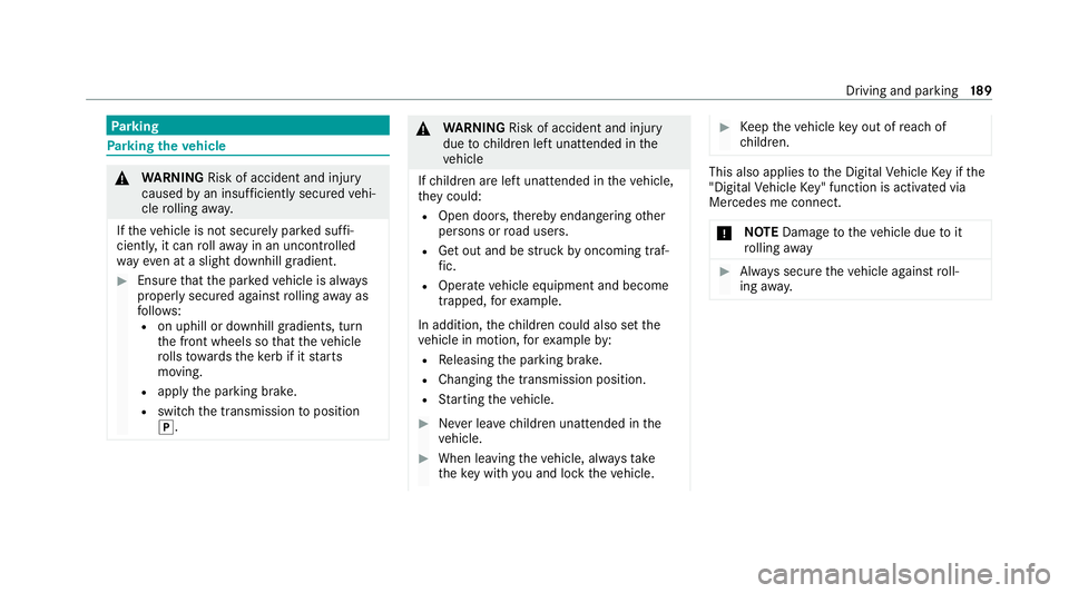
cle charging cable safely in theve hicle. Combo 2
vehicle soc ket #
Press "cancel charging" button 2.
or #
Unlock theve hicle (only charging with alter‐
nating cur rent mode 2/3).
The charging process is ended. The %
indicator lamp 1lights up white. The vehi‐
cle soc ket is unloc ked. #
AC charging mode 2/3: remo vethech arg‐
ing cable connec tor from theve hicle soc ket
within 30 seconds.
Af terth e 30 seconds ha veelapsed, theve hi‐
cle soc ket will be lo cked again and thech arg‐
ing process will resume.
% Ifyo u cannot remo vethech arging cable con‐
nec tor,re peat the unlocking procedure. If
th ech arging cable connec tor is still bloc ked,
con tact a qualified specialist workshop. #
Close the soc ket co ver and the soc ketflap. #
Remo vethech arging cable connec tor from
th e mains soc ket, or from the soc ket on the
wa llbox/ charging station, and stow theve hi‐
cle charging cable safely in theve hicle.
% Afterth ech arging cable connec tor has been
disconnected, the left % indicator lamp
1 ontheve hicle soc ketre mains lit for
some time before switching off. 18 8
Driving and pa rking
Page 192 of 629

Pa
rking Pa
rking theve hicle &
WARNING Risk of accident and inju ry
caused byan insuf ficiently secu redve hi‐
cle rolling away.
If th eve hicle is not securely par ked suf fi‐
ciently, it can rollaw ay in an uncont rolled
wa yev en at a slight downhill gradient. #
Ensure that the par kedve hicle is alw ays
properly secured against rolling away as
fo llo ws:
R on uphill or downhill gradients, turn
the front wheels so that theve hicle
ro lls towa rdsth eke rb if it starts
moving.
R apply the parking brake.
R switch the transmission toposition
j. &
WARNING Risk of accident and inju ry
due tochildren left unat tended in the
ve hicle
If ch ildren are left unat tended in theve hicle,
th ey could:
R Open doo rs,th ereby endangering other
persons or road users.
R Get out and be stru ck byoncoming traf‐
fi c.
R Ope rate ve hicle equipment and become
trapped, forex ample.
In addition, thech ildren could also set the
ve hicle in motion, forex ample by:
R Releasing the parking brake.
R Changing the transmission position.
R Starting theve hicle. #
Never lea vechildren unat tended in the
ve hicle. #
When leaving theve hicle, alw aysta ke
th eke y with you and lock theve hicle. #
Keep theve hicle key out of reach of
ch ildren. This also applies
tothe Digital Vehicle Key if the
"Digital Vehicle Key" function is activated via
Mercedes me connect.
* NO
TEDama getotheve hicle due toit
ro lling away #
Alw ays secure theve hicle against roll‐
ing away. Driving and pa
rking 18 9