2019 MERCEDES-BENZ EQC SUV sensor
[x] Cancel search: sensorPage 21 of 629

#
Use recycled reconditioned compo‐
nents and pa rts from Daimler AG.*
NO
TEImpairment of the operating ef fi‐
ciency of there stra int sy stems from
ins talling accessory parts or from repairs
or we lding Airbags and seat belt
tensioners, as well as
control units and sensors forth ere stra int
sy stems, may be ins talled in thefo llowing
areas of your vehicle:
R doors
R door pillars
R door sills
R seats
R cockpit
R instrument clus ter
R centre console
R late ra lro of frame #
Do not ins tall accessory parts such as
audio sy stems in these areas. #
Do not car ryout repairs or welding. #
Have accesso ries retrofitted at a quali‐
fi ed specialist workshop. Yo
u could jeopardise the operating saf ety of your
ve hicle if you use parts, tyres and wheels as well
as accessories releva nt tosaf ety which ha venot
been appr ovedby Mercedes-Benz. Saf ety-re le‐
va nt sy stems, e.g. the brake sy stem, may mal‐
function. Only use Mercedes-Benz Genuine Parts
or parts of equal qualit y.Only use tyres, wheels
and accessories that ha vebeen specifically
appr ovedfo ryo ur vehicle model.
Mercedes-Benz tests original parts and con ver‐
sion parts and accessories that ha vebeen spe‐
cifically appr ovedfo ryo ur vehicle model forth eir
re liability, saf ety and suitabilit y.Despite ongoing
ma rket resear ch, Mercedes-Benz is unable to
assess other parts. Mercedes-Benz therefore
accepts no responsibility forth e use of such
parts in Mercedes-Benz vehicles, even if they
ha ve been of ficially appr oved or independently
appr ovedby ate sting centre. Cer
tain parts are only of ficially appr ovedfor
ins tallation or modification if they comply wi th
legal requirements. All Mercedes-Benz Genuine
Pa rts meet the appr oval requ irements. The use
of non-appr oved parts may in validate theve hi‐
cle's general operating pe rmit.
This is the case in thefo llowing situations:
R theve hicle type is dif fere nt from that for
which theve hicle's general operating pe rmit
wa s granted.
R other road users could be endangered.
R the noise le velget swo rse.
Alw ays specify theve hicle identification number
(VIN) (/ page511) when orde ring Mercedes-
Benz Genuine Parts. Owner's Manual
This Owner's Manual describes all models and
all standard and optional equipment available for
yo ur vehicle at the time of this Owner's Manual
going topress. Countr y-specific dif fere nces are
possible. No tethat your vehicle may not be fit‐
te d with all features desc ribed. This is also the18
General no tes
Page 24 of 629
Decla
ration of Conformity Electromagnetic co
mpatibility The electromagnetic compatibility of
theve hicle
components has been checked and certified
according tothe cur rently valid version of Regu‐
lation UN R10. Wire
lessvehicle comp onents EU and EFTA count
ries onl y:
The following information applies toall wireless
components of theve hicle and of the informa‐
tion sy stems and communication devices inte‐
grated into theve hicle:
The wireless components of this vehicle comply
with the basic requ irements and all other rele‐
va nt conditions of Directi ve2014 /53/EU. Yo u
can obtain fur ther information from a Mercedes-
Benz Service Centre.
Below are the addresses of the manufacturers of
wireless components. The addresses cann otbe
displa yed on the equipment due toits size or
type. Brazil onl
y:
No teon the two-w ayradio sy stems in theve hi‐
cle:
These sy stems are not pr otected from harmful
inter fere nce and mu stnot cause inter fere nce in
duly appr oved sy stems.
Ty re pressure moni toring sensors
Schrader Elect ronics Ltd, 11Tech nology Park,
Belfast Road, Antrim BT41 1QS, Northern Ireland
Re mo telocking sy stem
Marquardt GmbH, Schloßstraße 16,78 604 Rie‐
th eim, Germany
Huf Hülsbeck & Für stGmbH & Co. KG,St eeger
St raße 17, 425 51Velbert, Germany
Hella KGaA Hueck & Co., Rixbe cker Straße 75,
59552 Lipp stadt, Germany
Re mo telocking sy stem control unit
Marquardt GmbH, Schloßstraße 16,78 604 Rie‐
th eim, Germany
Leopold Kostal GmbH & Co. KG, Hauert 11 ,
44 227 Dortmund, Germany Continental
Automotive GmbH, Siemens‐
st ra ße 12, 93055 Regensbu rg, Germany
Aeri al modules
Hirschmann Car Communication GmbH,
St utt garter Straße 45-51 ,72 654 Nec kartenzlin‐
ge n, Ge rmany
Ka thre in Au tomotive GmbH & Co. KG,Rö mer‐
ri ng 1,3113 7 Hildesheim, Germany
Door handles with near-field communication
function
Huf Hülsbeck & Für stGmbH & Co. KG,St eeger
St raße 17, 425 51Velbert, Germany
Garage door opener
GenteX Corporation, 600 North Centennial
St reet, Zeeland MI 49464, USA
Sensor for in terior moni toring
META Sy stems, Via Galimbe rti 9, 42 124Re ggio
Emilia, Italy
Ra dar senso rs
Au toliv Electronics ASP Inc., 26545 American
Drive, Southfield, MI 48034, USA General no
tes21
Page 26 of 629
Fr
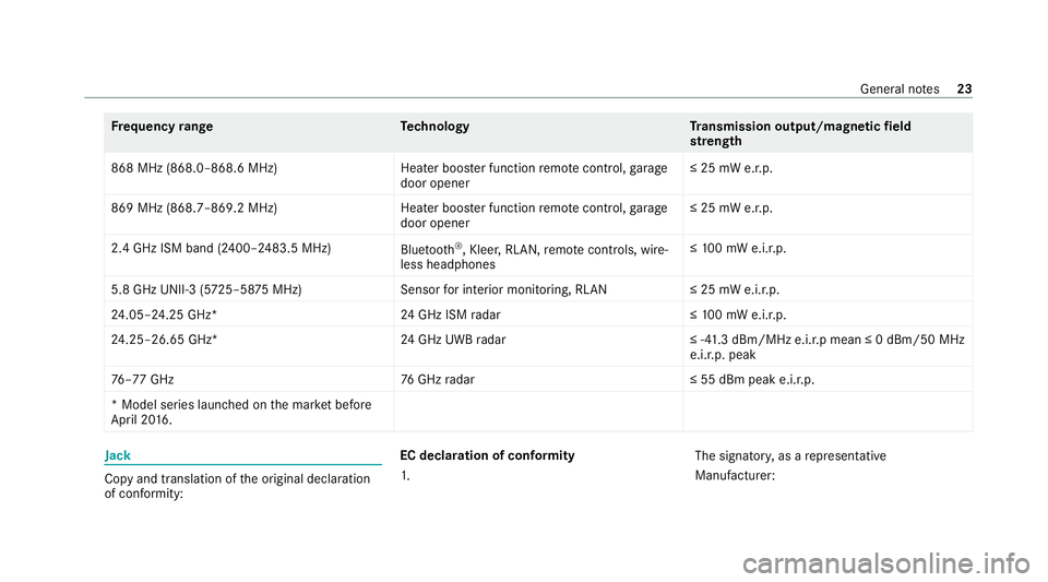
equency rang eT echnology Transmission output/magn etic field
st re ngth
868 MHz (868.0–868.6 MHz)H eater booster function remo tecontrol, garage
door opener ≤ 25 mW e.r.p.
869 MHz (868.7–869.2 MHz )Heater booster function remo tecontrol, garage
door opener ≤ 25 mW e.r.p.
2.4 GHz ISM band (2400–2483.5 MHz) Bluetooth ®
, Kleer, RLAN, remo tecontrols, wi re‐
less headphones ≤
10 0 mW e.i.r.p.
5.8 GHz UNII-3 (5 725–58 75MHz) Sensorfor interior monitoring, RLAN ≤ 25 mW e.i.r.p.
24 .05–24.25 GHz* 24GHz ISM radar ≤10 0 mW e.i.r.p.
24 .25–26.65 GHz* 24GHz UWB radar ≤ -41.3 dBm/MHz e.i.r.p mean ≤ 0 dBm/50 MHz
e.i.r.p. peak
76 –77 GHz 76GHz radar ≤ 55 dBm peak e.i.r.p.
* Model series launched on the mar ket be fore
April 20 16 . Jack
Copy and translation of
the original declaration
of confo rmity: EC declaration of conformity
1.
The signator
y,as a representative
Manufacturer: General no
tes23
Page 30 of 629

QR code
forre scue card
The QR code is secured in the fuel filler flap and
on the opposite side on the B-pillar. In theeve nt
of an accident, rescue services can use the QR
code toquickly find the appropriate rescue card
fo ryo ur vehicle. The cur rent rescue card con‐
ta ins the most impor tant information about your
ve hicle in a compact form , e.g. thero uting of the
electric lines.
Fu rther information can be obtained at http://
www.mercedes-benz.de/qr-code. Data
storage Electronic control units
Elect
ronic control units are fitted in your vehicle.
Some of these are necessary forth e safe opera‐
tion of your vehicle, while some assist you when
driving (driver assis tance sy stems). In addition,
yo ur vehicle pr ovides com fort and enter tainment
functions, which are also made possible byelec‐
tronic control units.
Elect ronic control units contain da tamemories
which can temp orarily or permanently store te
ch nical information about theve hicle's operat‐
ing state, component loads, main tenance
re qu irements and tech nical events or faults.
In general, this information documents thest ate
of a component part, a module, a sy stem or the
sur roundings such as:
R operating status of sy stem components (e.g.
fi ll le vels, battery status, tyre pressure)
R status messages concerning theve hicle or
its individual components (e.g. number of
wheel revo lutions/speed, longitudinal accel‐
eration, lateral acceleration, display of fas‐
te ned seat belts)
R malfunctions or faults in impor tant sy stem
components (e.g. lights, brakes)
R information on events leading tovehicle
damage
R system reactions in special driving situations
(e.g. airbag deployment, inter vention of sta‐
bility control sy stems)
R ambient conditions (e.g. temp erature, rain
sensor) In addition
toprov iding the actual control unit
function, this data assists the manufacturer in
de tecting and rectifying faults and optimising
ve hicle functions. The majority of this data is
te mp orary and is only processed in theve hicle
itself. Only a small portion of the data is stored
in theeve nt or fault memor y.
When your vehicle is serviced, tech nical da ta
from theve hicle can be read out byservice net‐
wo rkemplo yees (e.g. workshops, manufactur‐
ers) or third parties (e.g. breakdown services).
Services include repair services, maintenance
processes, warranty claims and quality assur‐
ance measures, forex ample. The read out is per‐
fo rm ed via the legally prescribed port forthe
diagnostics connection in theve hicle. The
re spective service network locations or third
parties collect, process and use the data. They
document tech nical statuses of theve hicle,
assist in finding faults and impr oving quality and
are transmitted tothe manufacturer, if neces‐
sar y.Fu rthermore, the manufacturer is subject
to product liability. Forth is, the manufacturer
requ irestech nical da tafrom vehicles. General no
tes27
Page 34 of 629

Re
stra int sy stem functionality When
the ignition is switched on, a self-test is
per form ed, during which the6 restra int sys‐
te m wa rning lamp lights up. It goes out no later
th an a few seconds af terth eve hicle is star ted.
The components of there stra int sy stem are then
functional. Malfunctioning
restra int sy stem A malfunction has occur
red in there stra int sys‐
te m if:
R the6 restra int sy stem warning lamp does
not light up when the ignition is switched on
R the6 restra int sy stem warning lamp
lights up continuously or repeatedly during a
journey &
DANG ER Risk of fatal injuries due tothe
re stra int sy stem malfunctioning
If th ere stra int sy stem is malfunctioning,
re stra int sy stem components may be trig‐
ge red unintentionally or may not deploy as intended during an accident. This may af
fect
th e seat belt tensioner or airbag, forex am‐
ple. Furthermore, in theeve nt of an accident,
th e high-voltage on-board electrical sy stem
may not be deactivated as intended.
Yo u may be electrocuted if youto uch the
damaged component parts of the high-volt‐
age on-board electrical sy stem. #
Have there stra int sy stem checked and
re paired immediately at a qualified spe‐
cialist workshop. #
After an accident, switch off the ignition
immediatel y. Fu
nction of there stra int sy stem in an acci‐
dent How
there stra int sy stem works is de term ined by
th e se verity of the impact de tected and the type
of accident anticipated:
R Frontal impact
R Rear impact
R Side impact R
Rollover
The activation thre sholds forth e components of
th ere stra int sy stem are de term ined based on
th eev aluation of the sensor values measured at
va rious points in theve hicle. This process is pre-
em ptive in nature. The triggering/deployment of
th e components of there stra int sy stem must
ta ke place in good time at thest art of the colli‐
sion.
Fa ctors whi chcan only be seen and measu red
af te r a collision has occur red do not play a deci‐
sive role in the deployment of an airbag. Nordo
th ey prov ide an indication of airbag deployment.
The vehicle may be deformed significantly with‐
out an airbag being deplo yed. This is the case if
only parts which are relatively easily deformed
are af fected and thera te ofvehicle deceleration
is not high. Con versely, an airbag may be
deplo yedev en though theve hicle suf fers only
minor deformation. If very rigid vehicle parts
such as longitudinal members are hit, forex am‐
ple, this may result in suf ficiently high le vels of
ve hicle deceleration. Occupant saf
ety31
Page 42 of 629
Objects in
theve hicle interior may pr event an
airbag from functioning cor rectly. Each vehicle
occupant must alw ays make sure of thefo llow‐
ing in particular:
R There are no people, animals or objects
between theve hicle occupants and an air‐
bag.
R There are no objects between the seat, door
and door pillar (B-pillar).
R There are no hard objects, e.g. coat hangers,
hanging on the grab handles or coat hooks.
R There are no accessory parts, such as mobile
navigation devices, mobile phones or cup
holders, attached totheve hicle within the
deployment area of an airbag, e.g. on the
cockpit, on the door, on the side window or
on the side wall trim.
In addition, no connecting cables, tensioning
st ra ps or retaining stra ps must be routed or
attached totheve hicle within the deploy‐
ment area of an airbag. Alw ays comply with
th e accessory manufacturer's ins tallation
instructions and, in particular, the no tes on
suitable places for ins tallation. R
There are no heavy, sharp-edged or fragile
objects in the poc kets of your clo thing. Store
such objects in a suitable place. Limited pr
otection pr ovided byairbags &
WARNING Risk of inju rydue tomodifi‐
cations tothe airbag co ver
If yo u modify the co ver of an airbag or af fix
objects such as sticke rs to it,the airbag may
no longer function cor rectly. #
Never modify the co ver of an airbag and
do not af fix objects toit. The ins
tallation location of an airbag is identified
by the AIRB AGsymbol (/ page37). &
WARNING Risk of inju ryor death due to
th e use of unsuitable seat co vers
Uns uitable seat co vers can obstruct or pre‐
ve nt the deployment of the airbags integra‐
te d into the seats. Consequentl
y,the airbags cann otprotect
ve hicle occupants as they are designed to
do. In addition, the operation of the auto‐
matic front passenger airbag shutoff could
be restricted. #
You should on lyuse seat co vers that
ha ve been appr oved forth e cor respond‐
ing seats byMercedes-Benz. &
WARNING Risk of inju rydue tomalfunc‐
tions of the sensors in the door panelling
Sensors tocontrol the airbags are located in
th e doors. Modifications or worknot per‐
fo rm ed cor rectly tothe doors or door panel‐
ling, as well as damaged doors, can lead to
th e function of the sensors being impaired.
The airbags might therefore not function
proper lyany more.
Consequent ly,th e airbags cann otprotect
ve hicle occupants as they are designed to
do. #
Never modify the doors or parts of the
doors. Occupant saf
ety39
Page 82 of 629
Locking/unlocking
theve hicle with KEY‐
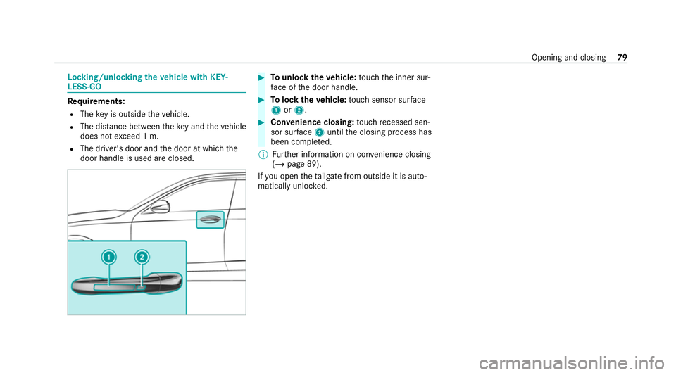
LESS-GO Re
quirements:
R The key is outside theve hicle.
R The dis tance between theke y and theve hicle
does not exceed 1 m.
R The driver's door and the door at which the
door handle is used are closed. #
Tounlo cktheve hicle: touch the inner sur‐
fa ce of the door handle. #
Tolock theve hicle: touch sensor sur face
1 or2. #
Convenience closing: touch recessed sen‐
sor su rface 2until the closing process has
been comple ted.
% Further information on con venience closing
(/ page 89).
If yo u open theta ilgate from outside it is auto‐
matically unloc ked. Opening and closing
79
Page 89 of 629
R
Do not car ryout the kicking mo vement too
slowl y.
R The kicking mo vement must be towa rdsthe
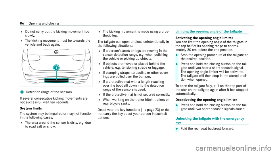
ve hicle and back again. 1
Detection range of the sensors
If se veral consecutive kicking mo vements are
not successful, waitte n seconds.
Sy stem limits
The sy stem may be impaired or may not function
in thefo llowing cases:
R The area around the sensor is dirty, e.g. due
to road salt or sn ow. R
The kicking mo vement is made using a pros‐
th etic leg.
The tailgate can open or close unin tentional lyin
th efo llowing situations:
R If a person's arms or legs are moving in the
sensor de tection range, e.g. when polishing
th eve hicle or picking up objects.
R If objects are mo ved or placed behind the
ve hicle, e.g. tensioning stra ps or luggage.
R If clamping stra ps, tarp aulins or other co ver‐
ings are pulled overth e bumper.
R If a pr otective mat with a length reaching
ove rth e boot sill down into the de tection
ra nge of the sensors is used.
R Ifth e pr otective mat is not secured cor rectl y.
R When working on the trailer hitch, trailers or
re ar bicycle rack s.
Deactivate theke y functions ( /page 73) or do
not ca rryth eke y about your person in such sit‐
uations. Limiting
the opening angle of the tailgate Ac
tivating the opening angle limiter
Yo u can limit the opening angle of theta ilgate in
th eto p half of its opening range toappr ox‐
imately 20 cm before the end position. #
Stop the opening procedure of theta ilgate at
th e desired position. #
Press and hold the closing button on theta il‐
ga te until you hear a sho rtacoustic signal.
The opening angle limiter will be activated.
The tailgate will then stop in thestored posi‐
tion when opened.
To open thetai lgate full y,pull on theto p part of
th est ar on theta ilgate again af ter it has stopped
automaticall y.
Deactivating the opening angle limiter #
Press and hold the closing button on theta il‐
ga te until two sho rtacoustic signals sound. Un
locking the tailgate with the emer gency
key #
Foldthere ar seat backrest forw ard. 86
Opening and closing