Page 369 of 398

a co ...... N r--. N ...... 0
0
:E '
Fuse assignment - Driver's side of the
cockpit
Fig . 28 6 Driver s ide cockp it : fuse panel wit h plastic bracket
Fuse panel
No . Equipment
2 Telephone
4 Head- up display
5 Aud i m usic interface, USB charging port
6 Front climate co ntro l system contro ls
7 Steer ing column lock
8 Infotainment sys tem display
9 Instrument cluste r
10 Infotainment unit
1 1 Light switch
12 Steerin g column electronics
14 Infotainmen t sys tem
1 5 Powe r steering co lumn adjustment
16 Steeri ng whee l heating
Fuses and bulbs
Fuse assignment - Left side of the luggage
compartment
F ig. 28 7 Le ft s ide of the l uggage co mpart ment : fuse pa nel
wi th plastic cl ip
Fuse panel @ (black)
No . Equipment
s Air s usp ension
6 A utomat ic t ransmiss io n
8 Rear seat heat ing
9 T ail ligh ts
10 Left safety belt tensioner
11 C en tral locki ng sys tem
12 Electric luggage compartment lid
Fuse panel @ (red)
No. Equipment
1 Rear blower control
2 Sound -amplifier
3 Ad Blue heat ing
4 Rear cl imate co ntro l system contro l pane l
s Traile r hitc h (right lig ht)
7 Tra ile r hi tc h
8 Tra ile r hitc h (left light)
9 Tra ile r hitc h (soc ket)
10 Sport different ia l
367
...
Page 370 of 398

Fuses and bulb s
Fuse panel@ (red )
11 AdBlue heating
12 Third row seats
Fus e panel © (brown)
N o. Equip ment
2 Telephone
3 Lumba r suppo rt
4 Audi side assist
8 Sma rt mod ule (tank)
9 CD /DVD player
12 Homelink
13 Rearview camera, per
ipheral cameras
14 Right tail lights
16 Right safety belt tensioner
Fu se panel @ (red )
N o.
I Equipment
Bulbs
Replacing light bulbs
For your safety, we recommend that you have
your authorized Audi dealer replace any bulbs for
you.
I t is becoming increasing ly more and more diffi
cult to replace vehicle light bulbs since in many
cases, other parts of the car must first be re moved before you are able to get to the bulb.
This applies espec ially to the light bulbs in the
front of your car wh ich you can only reach
through the eng ine compartment.
Sheet metal and bulb ho lders can have sharp
edges that can cause ser ious cuts, parts must be
correctly taken apart and then properly put back
together to help prevent breakage of parts and long term damage from water that can enter
housings that have not been proper ly resea led.
For your safety, we recommend that you have
your author ized Audi dealer replace any bulbs for
you, s ince your dealer has the proper tools, the
correct bulbs and the expert ise.
G as disc harg e la m ps (Xe non light s):
368
Due to the high e lectrica l voltage, have the bulbs
rep laced by a qualified technician. Headlights
with Xenon light are identif ied by the high volt
age sticker.
LED h eadlights*
LE D headlights requ ire no maintenance. Please
contact your author ized Audi dealer if a bulb
needs to be rep laced.
& WARNING
Changing Xenon lamps without the necessary
equipment can cause serious personal injury.
- Bulbs are pressurized and can exp lode when
being changed. Potential risk of injury!
- On veh icles equipped with gas discharge
bulbs (Xenon light) life -threatening injuries
can result from improper handling of the high-vo ltage portions of such lamps!
- On ly your authorized A udi dealer or quali
fied workshop shou ld change the bulbs in
gas discharge lamps. There are parts with
sharp edges on the openings and on the bulb holders that can cause serious cuts . If
you are uncerta in about what to do, have
the work performed by an authorized Audi
dea le r o r qualified workshop. Ser ious per
sonal injury may result from improperly per
formed work.
© Tips
- If you still prefer to replace the light bulbs
yourself, be awa re that the engine compa rt
ment is a hazardous area to work in ~ .&.
in
Working in the engine compartment on
page 319 .
-It is best to ask your authorized Audi dealer
whenever you want to change a bulb .
Page 371 of 398

Cl a:, ...... N
" N ...... 0
0
::r '
Emergency situations
General
This chapter is intended for trained emergency
crews and working personnel who have the nec
essary tools and equipment to perform these
operations.
Starting by pushing or
towing
~ Note
Vehicles with an automatic transmission
cannot be started by pushing or towing.
Starting with jumper
cables
If necessary , the engine can be started by con
necting it to the battery of another vehicle.
If the engine should fail to start because of a dis
charged or weak battery, the battery can be con
nected to the battery of
another vehicle, using a
pair of jumper cables to start the engine.
Jumper cables
Use only jumper cables of sufficiently large cross
section
to carry the starter current safely. Refer
to the manufacturer's specifications.
Use only jumper cables with
insulated terminal
clamps which are distinctly marked :
plus(+) cable in most cases colored red
minus(-) cable
in most cases colored black.
A WARNING -
Batteries contain electricity, acid, and gas.
Any of these can cause very serious or fatal in
jury. Follow the instructions below for safe
handling of your vehicle's battery.
-Always shield your eyes and avoid leaning
over the battery whenever possible.
- A dead battery can freeze at temperatures
around 32 °F (0 °C) . If the vehicle battery is
frozen, you must thaw it before connecting
the jump start cables. If you do not, this in-
Emergency situations
creases the risk of an explosion and chemi
cal burns. After jump starting the vehicle,
drive to an authorized Audi dealer or author
ized Audi Service Facility immediately to
have the vehicle battery checked.
- Do not allow battery acid to contact eyes or
skin . Flush any contacted area with water
immediately.
- Improper use of a booster battery to start a
vehicle may cause an explosion .
- Vehicle batteries generate explosive gases .
Keep sparks, flame and lighted cigarettes
away from batteries.
- Do not try to jump start any vehicle with a
low acid level in the battery .
- The voltage of the booster battery must also
have a 12-Volt rating . The capacity (Ah) of
the booster battery should not be lower
than that of the discharged battery. Use of
batteries of different voltage or substantial
ly different "Ah " rating may cause an explo
sion and personal injury.
- Never charge a frozen battery. Gas trapped
in the ice may cause an explosion.
- Never charge or use a battery that has been
frozen. The battery case may have be weak
ened.
- Use of batteries of different voltage or sub
stantially different capacity (Ah) rating may
cause an explosion and injury. The capacity
(Ah) of the booster battery should not be
lower than that of the discharged battery.
- Before you check anything in the engine
compartment, always read and heed all
WARNINGS
c>page 319.
@ Note
-Applying a higher voltage booster battery
will cause expensive damage to sensitive
electronic components, such as control
units, relays, radio, etc.
- There must be no electrical contact between
the vehicles as otherwise current could al
ready start to flow as soon as the positive
( + ) terminals are connected.
369
Page 372 of 398

Emergency situations
@ Tips
The discharged battery must be properly con
nected to the vehicle's electrical system .
When jump starting or charging the battery,
never connect the negative ground cable to
the battery negative post because the battery
manager system must be able to detect the
battery's state of charge. Always connect the
negat ive g round cable to the negative ground
post of the battery manager control unit.
Using the jump start
cable
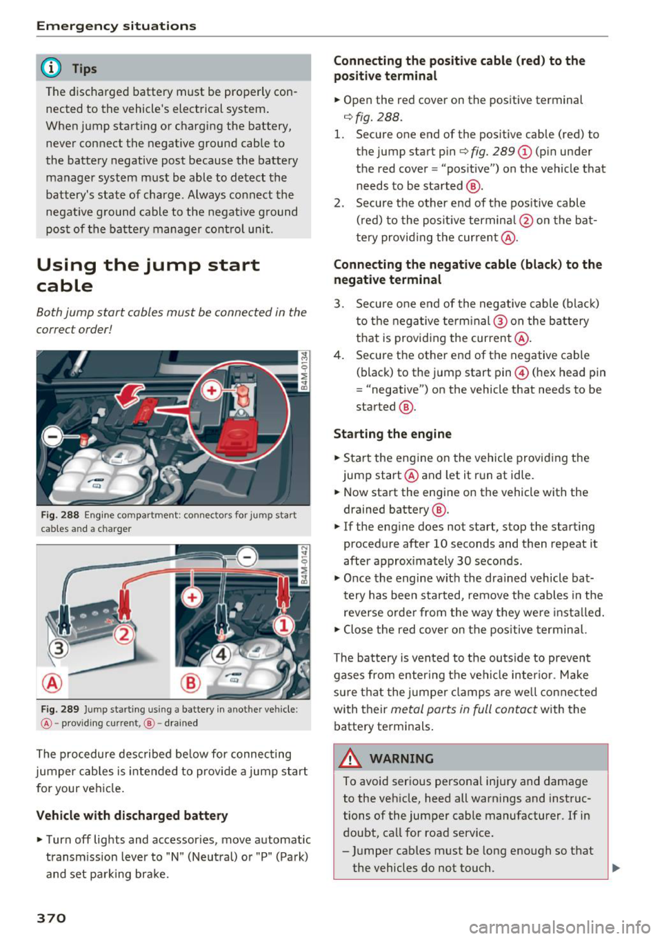
Both jump start cables must be connected in the
correct order!
Fig. 288 E ngin e compartme nt: co nn ectors for jump start
cables and a charger
Fig. 289 Jump starting using a battery in anot her vehicle:
@-pro vidi ng current, @-dra ined
The procedure described below for connecting
jumper cables is intended to provide a jump start
for your vehicle.
Vehicle with discharged battery
... Turn off lights and accessories, move automatic
transm ission lever to "N" (Neutral) or "P" (Pa rk)
and set parking bra ke.
370
Connecting the positive cable (red) to the
positive terminal
... Open the red cover on the positive terminal
c:::>fig. 288.
1. Secure one end of the pos itive cable (red) to
the jump start pin
c:::> fig. 289 (J) (pin under
the red cover = "pos itive") on the veh icle that
needs to be started @.
2. Secure the other end of the positive cable
(red) to the posit ive terminal @on the bat
tery provid ing the cur rent @.
Connecting the negative cable (black) to the
negative terminal
3. Secure one end of the negative cable (black)
to the negative terminal @ on the battery
that is providing the current @.
4. Secure the other end of the negative cable
(black) to the jump start pin@ (hex head pin
= "negative") on the vehicle that needs to be
started @.
Starting the engine
... Sta rt the eng ine on the vehicle providing the
jump start @and let it run at idle .
... Now start the engine on the vehicle with the
drained battery @.
... If the engine does not start, stop the starting
procedure after 10 seconds and then repeat it
after approx imately 30 seconds.
"' Once the engine w it h the drained vehicle bat
tery has been started, remove the cables in the
reverse order from the way they were install ed.
"' Close the red cover on the positive terminal.
The battery is vented to the outside to prevent
gases from enter ing the vehicle inter ior. Make
sure th at the j umper clamps are well connected
with their
metal ports in full contact with the
battery terminals .
A WARNING
-To avoid serious personal injury and damage
to the vehicle, heed all warnings and instruc
tions of the jumper cable manufacturer. If in
doubt, call for road service .
- Jumper cables must be long enough so that
the vehicles do not touch. ..,.
Page 373 of 398

-When connecting jumper cables, make sure
that they cannot get ca ught in any mov ing
parts in the engine compartment.
- Do not bend over the batteries - danger of
chem ica l burns!
- The battery cell lock ing screws must be
t ightened sec ure ly.
- Be fore you check anything in the e ngine
compartment, a lways read and hee d all
WAR NINGS
q page 319.
(D Note
Impro per hook -up of jum pe r cables can r uin
the gene rato r.
- Always connect POSITI VE (+ ) to POS ITIV E
( + ), and NEGATIVE( -) to NEGAT IVE( -)
g roun d post of t he battery mana ger contro l
u nit.
- Check that a ll sc rew p lugs on t he battery
cells are screwed in firmly. I f not, t ighten
plugs prior to connecting clamp on negative
batte ry terminal.
- Please note that the procedure fo r con nect
i ng a jumper cab le as desc ribed above ap
p lies specifica lly to the case of yo ur vehicle
being jump starte d. When you are giv ing a
ju mp s ta rt to anothe r vehicle, do
not con
n ect the neg ative (-) cab le to the neg ative
(-) t ermin al on the di sch arged b attery @
q fig. 289. In ste ad , securely connec t the
nega tive ( -) cab le to either a solid me tal
com ponent that is f irm ly bolted to the e n
gine block o r to the engine bloc k itself. If
the battery that is be ing cha rge d does not
vent to the outs ide, escap ing battery gas
could ignite and exp lode!
Towing with a tow truck
General hints
Your Audi requires special handling for towi ng .
The fo llow ing information is to be used by com
mercia l tow tr uck operators who know how to op-
~ e rate the ir equip ment safe ly .
...... N ~ - Never tow your Audi, towing will cause dam-,.....
g age to the engine and transmission .
:E '
Emergency situations
-Never wrap the safety chains or winch cables
around the brake lines .
- To prevent unnecessa ry damage , your Audi
must be transported with a flatbed truck.
- To load the vehicle on to the flatbed, use the
towing loop found in the vehicle tools and at
tach to the front or rear anchorage
¢ page371 and ¢page 372.
A WARNING
-A veh icle being towed is not safe for passen-
ge rs. Neve r allow anyone to ride in a vehicle
b eing towed, fo r any r eason.
Front towing loop
Only install the front towing loop when it is
needed.
Fig . 290 Front bumper (cover) : installing th e towing loop
Fig. 291 F ro nt bumper (trim): i nsta lling the towing loop
T he threaded o pening for the towing loop is lo
c ate d on the right s ide of the front bu mper.
.,. Remove the towing loo p from the vehicle tool
ki t
¢ pag e 357.
.,. Press the cap inw ard with brief, forceful pres
sure ¢
fig. 290 . The cap will loosen from the
bumper . ..,.
371
Page 374 of 398

Emergency situations
,.. Or: pull sharply on the trim in the direction of
the arrow to remove
¢fig. 291.
,.. Tighten the towing loop in the threaded open
ing until it stops and then tighten it with a
wheel wrench.
,.. After using, place the towing loop back in the
vehicle tool kit.
,& WARNING
If the towing loop is not tightened until it
stops when insta lling, the threads may be
pulled out when towing the vehicle and tha t
could cause an accident .
(D Note
The trim is attached to the bumper with sev
eral hooks. To redu ce the r isk of damage, do
not use any force when removing and instal
ling.
Rear towing loop
Fig. 292 Rear bumper: installing the tow ing loop
Vehicles with a towing loop
On veh icles w ithout a factory-installed trailer
h itch*, the towing loop threads are located on
the right rear side of the bumper.
-
,.. Remove the tow ing loop from the veh icle tool
kit
¢page 357.
• Press the cap inward with b rief, forcefu l pres
s u re~
fig. 292. The cap will loosen from the
bumper.
.. Tighten the towing loop in the threaded open
ing until it stops and then tighten it with a
wheel wrench.
,.. After using, place the towing loop back in the
vehicle tool kit.
372
Vehicles with a trailer hitch*
"' Attach the towing bar or the towing cable to
the trailer hitch.
Vehicles with a factory-installed trailer hitch* are
not equipped with towing loop threads at the
r ear.
,& WARNING
If the towing loop is not tightened until it
stops when installing, the threads may be
pulled out when towing the vehicle and that
could cause an accident.
A WARNING
Applies to: vehicles with trailer hitch
-Only use a special towing bar to prevent
damaging the ball hitch. These towing bars
have been specially designed for trailer tow
ing h itches.
- Only use special towing cables.
Loading the vehicle onto a flatbed truck
Fig. 293 Ve hicle on flatbed truck
Front hook up
.. Align the vehicle with the centerline of the car
carrier ramp.
• Attach the winch hook to the front towline eye
previously installed .
Rear hook up
,.. Align the vehicle with the centerline of the car
carrier ramp.
• Attach the w inch hook to the rear towline eye
previously installed . ..,
Page 375 of 398

a co ...... N r--. N ...... 0
0
:E "
(D Tips
Check carefu lly to make sure the hoo k-up is
secure befo re moving the car up the f latbe d
truck ramp.
Raising the vehicle
Lifting with workshop hoist and with floor
jack
The vehicle may only be li~ed at the lifting
point s illus tra ted .
~ ---L.- -f-L---==- ---~
c!i
Fig . 294 F ro nt lift ing poin t
Fig . 295 Re ar lift ing poin t
.,. Read and heed WARNING c::> &_ .
.,. Locate lift ing po ints c:> fig . 294 and c:> fig . 295 .
.,. Adjust lifting arms of wo rkshop ho ist or floo r
jac k to matc h ve hicle lifting points .
.,. In se rt a r ubber pa d be tween t he floor jack/
wor kshop hois t and the li fting poin ts.
If you must lift your vehicle with a floor jack to
work underneath , be sure the vehicle is safely
supported on stands intended for thi s purpose .
Front lifting point
The lift ing po int is located on the floor pan re in
forcement about at the same level as the jack
Emergency situations
mounting point c::> fig . 294 . Do not lift the vehi
cle at the vertical sill reinforcement .
Rear lifting point
The lifting poi nt is lo cate d on the ve rtic al rein
f orceme nt of the lowe r si ll for the on board j ack
c:> fig. 295 .
Lifting with vehicle jack
Refer to c::> page 360.
_&, WARNING
-- T o reduc e th e ris k of se rious injury and veh i
cle da mage.
- Al ways lift the vehicle on ly a t the special
workshop hoist and f loor jack lift points i l
lustrated
c::> fig . 294 and c::> fig. 295.
-Failure to lift the ve hicle at these points
could cause the veh icle to t ilt or fall from
a lift if t he re is a cha nge in vehicle we ight
dist ribution and balance . This might hap
pen, fo r exampl e, when he avy compo
nen ts such as the engin e block o r trans
mission a re removed .
- Wh en remov ing h eavy components like
t he se, ancho r ve hicle to hoist or add co rre
spon ding weig hts to m aint ain t he cen ter o f
g ra vity. Ot he rw ise, the vehicle mig ht tilt or
sli p off the hoist, c ausing se rio us pe rson al
in jur y.
Ci) Note
- B e aware of the follow ing poi nt s bef or e lift
ing the vehicle:
-The vehicle should never be lifted or
jacked up from underneath the engine oil pan, the transmission housing, the front
or rear axle or the body side members .
This could lead to serious damage.
- To avoid damage to the underbody or
chassis frame, a rubber pad must be in
serted between the floor jack and the lift
points .
- Before driving over a workshop hoist,
check that the vehicle weight does not
exceed the permissible lifting capacity of
the hoist. ..,.
373
Page 376 of 398
Emergency situations -Before driving over a workshop hoist, en
sure that there is sufficient clearance be
tween the hoist and low parts of the ve
hicle.
Vehicle transport
Applies to: vehicles with air suspension
The following contains information you should
know about transporting your vehicle.
(LlJ Note
W he n tra nsp orting t he vehi cle on a ca r ca rr i
er, tra in, shi p or by ot her means, only tie the
veh icle d own at t he r unnin g surface of the
tires, w hich is the outer circumference. Secur
ing the vehicle at the axle components, sus
pens io n struts or tow ing eyes is not pe rm itted
because the pressure in the air suspe nsio n
s tr uts ca n ch an ge dur ing transp ort. Th e ve hi
cle may not be se cur ed suf ficientl y if this hap
pe ns.
374