2016 NISSAN NOTE steering wheel
[x] Cancel search: steering wheelPage 1605 of 3641
![NISSAN NOTE 2016 Service Repair Manual EC-478
< SERVICE DATA AND SPECIFICATIONS (SDS) [HR16DE]
SERVICE DATA AND SPECIFICATIONS (SDS)
SERVICE DATA AND SPECIFICATIONS (SDS)
SERVICE DATA AND SPECIFICATIONS (SDS)
Idle SpeedINFOID:0000000012431 NISSAN NOTE 2016 Service Repair Manual EC-478
< SERVICE DATA AND SPECIFICATIONS (SDS) [HR16DE]
SERVICE DATA AND SPECIFICATIONS (SDS)
SERVICE DATA AND SPECIFICATIONS (SDS)
SERVICE DATA AND SPECIFICATIONS (SDS)
Idle SpeedINFOID:0000000012431](/manual-img/5/57363/w960_57363-1604.png)
EC-478
< SERVICE DATA AND SPECIFICATIONS (SDS) [HR16DE]
SERVICE DATA AND SPECIFICATIONS (SDS)
SERVICE DATA AND SPECIFICATIONS (SDS)
SERVICE DATA AND SPECIFICATIONS (SDS)
Idle SpeedINFOID:0000000012431675
*: Under the following conditions
• A/C switch: OFF
• Electric load: OFF (Lights, heater fan & rear window defogger)
• Steering wheel: Kept in straight-ahead position
Ignition TimingINFOID:0000000012431676
*: Under the following conditions
• A/C switch: OFF
• Electric load: OFF (Lights, heater fan & rear window defogger)
• Steering wheel: Kept in straight-ahead position
Calculated Load ValueINFOID:0000000012431677
Mass Air Flow SensorINFOID:0000000012431678
*: Engine is warmed up to normal operating temperature and running under no load.Transmission Condition Specification
CVT No load* (in P or N position) 650 ± 50 rpm
M/T No load* (in Neutral position) 650 ± 50 rpm
Transmission ConditionSpecification
CVT No load* (in P or N position) 4 ± 5 °BTDC
M/T No load* (in Neutral position) 10 ± 5°BTDC
Condition Specification (Using CONSULT or GST)
At idle 10 – 35%
At 2,500 rpm 10 – 35%
Supply voltageBattery voltage (11 – 14 V)
Output voltage at idle 0.8 – 1.3 V*
Mass air flow (Using CONSULT or GST) 0.8 – 4.0 g/s at idle*
2.0 – 10.0 g/s at 2,500 rpm*
Revision: August 2015 2016 Versa Note
cardiagn.com
Page 1759 of 3641
COMBINATION SWITCHEXL-107
< REMOVAL AND INSTALLATION >
C
DE
F
G H
I
J
K
M A
B
EXL
N
O P
COMBINATION SWITCH
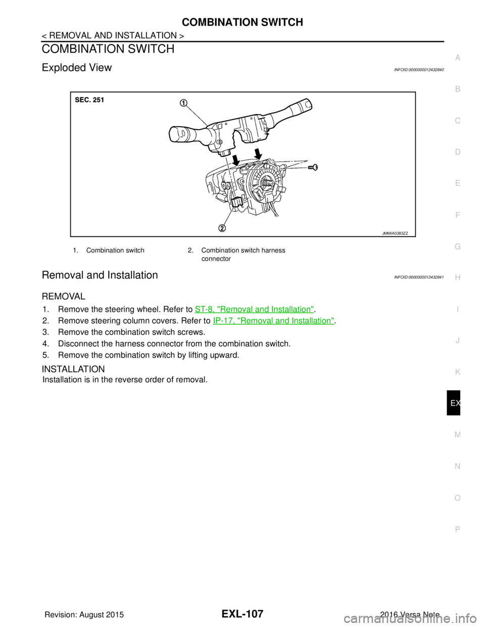
Exploded ViewINFOID:0000000012432840
Removal and InstallationINFOID:0000000012432841
REMOVAL
1. Remove the steering wheel. Refer to ST-8, "Removal and Installation".
2. Remove steering column covers. Refer to IP-17, "
Removal and Installation".
3. Remove the combination switch screws.
4. Disconnect the harness connector from the combination switch.
5. Remove the combination switch by lifting upward.
INSTALLATION
Installation is in the reverse order of removal.
1. Combination switch 2. Combination switch harness
connector
JMMIA0383ZZ
Revision: August 2015 2016 Versa Note
cardiagn.com
Page 1819 of 3641
FAX-2
< PRECAUTION >
PRECAUTIONS
PRECAUTION
PRECAUTIONS
Precaution for Supplemental Restraint System (SRS) "AIR BAG" and "SEAT BELT
PRE-TENSIONER"
INFOID:0000000012431882
The Supplemental Restraint System such as “A IR BAG” and “SEAT BELT PRE-TENSIONER”, used along
with a front seat belt, helps to reduce the risk or severity of injury to the driver and front passenger for certain
types of collision. Information necessary to service the system safely is included in the SR and SB section of
this Service Manual.
WARNING:
• To avoid rendering the SRS inopera tive, which could increase the risk of personal injury or death in
the event of a collision which would result in air bag inflation, all maintenance must be performed by
an authorized NISSAN/INFINITI dealer.
• Improper maintenance, including in correct removal and installation of the SRS, can lead to personal
injury caused by unintent ional activation of the system. For re moval of Spiral Cable and Air Bag
Module, see the SR section.
• Do not use electrical test equipmen t on any circuit related to the SRS unless instructed to in this
Service Manual. SRS wiring harn esses can be identified by yellow and/or orange harnesses or har-
ness connectors.
PRECAUTIONS WHEN USING POWER TOOLS (AIR OR ELECTRIC) AND HAMMERS
WARNING:
• When working near the Airbag Diagnosis Sensor Unit or other Airbag System sensors with the Igni-
tion ON or engine running, DO NOT use air or electri c power tools or strike near the sensor(s) with a
hammer. Heavy vibration could activate the sensor( s) and deploy the air bag(s), possibly causing
serious injury.
• When using air or electric power tools or hammers , always switch the Ignition OFF, disconnect the
battery and wait at least three minutes before performing any service.
Precaution for Drive ShaftINFOID:0000000012431883
Observe the following precautions when disassembling and assembling drive shaft.
• Do not disassemble joint sub-assembly because it is non-overhaul parts.
• Perform work in a location which is as dust-free as possible.
• Clean the parts, before disassembling and assembling.
• Prevent the entry of foreign objects dur ing disassembly of the service location.
• Reassemble disassembled parts carefully in the correct order. If work is interrupted, a clean cover must be placed over parts.
• Use paper waste. Fabric shop cloths must not be used because of the danger of lint adhering to parts.
• Clean disassembled parts (except for rubber parts) with kerosene which shall be removed by blowing with air or wiping with paper waste.
Precautions for Wheel Hub and KnuckleINFOID:0000000012431884
Observe the following precautions when assembling wheel hub and knuckle.
• Perform work in a location which is as dust-free as possible.
• Use paper waste. Fabric shop cloths must not be used because of the danger of lint adhering to parts.
• If any of wheel hub, steering knuckle, wheel bearing, and wheel hub lock nut is dropped, it must not be used.
• Always check that the tools used for press-fit work of wheel hub and wheel bearing have no wear and defor- mation so that a pressure can be applied vertically.
Revision: August 2015 2016 Versa Note
cardiagn.com
Page 1823 of 3641

FAX-6
< SYMPTOM DIAGNOSIS >
NOISE, VIBRATION AND HARSHNESS (NVH) TROUBLESHOOTING
SYMPTOM DIAGNOSIS
NOISE, VIBRATION AND HARSHNESS (NVH) TROUBLESHOOTING
NVH Troubleshooting ChartINFOID:0000000012431887
Use chart below to find the cause of the symptom. If necessary, repair or replace these parts.
×: ApplicableReference
—
FAX-8—
FAX-8—
FSU-5FSU-5—
WT-45WT-44—
BR-7ST-7
Possible cause and SUSPECTED PARTS
Excessive joint angle
Joint sliding resistance
Imbalance
Improper installation, looseness
Parts interference
Wheel bearing damage
FRONT SUSPENSION
FRONT AXLE
TIRE
ROAD WHEEL
DRIVE SHAFT
BRAKE
STEERING
Symptom DRIVE
SHAFT
Noise
××××××× ××
Shake × × ××××× ××
FRONT
AXLE Noise
×××× ×××××
Shake ×××× ×××××
Vibration ×××××××
Shimmy ×××××××
Shudder × × ×× ××
Poor quality ride or handling ×××××
Revision: August 2015 2016 Versa Note
cardiagn.com
Page 1826 of 3641
FRONT WHEEL HUB AND KNUCKLEFAX-9
< REMOVAL AND INSTALLATION >
CEF
G H
I
J
K L
M A
B
FA X
N
O P
REMOVAL AND INSTALLATION
FRONT WHEEL HUB AND KNUCKLE
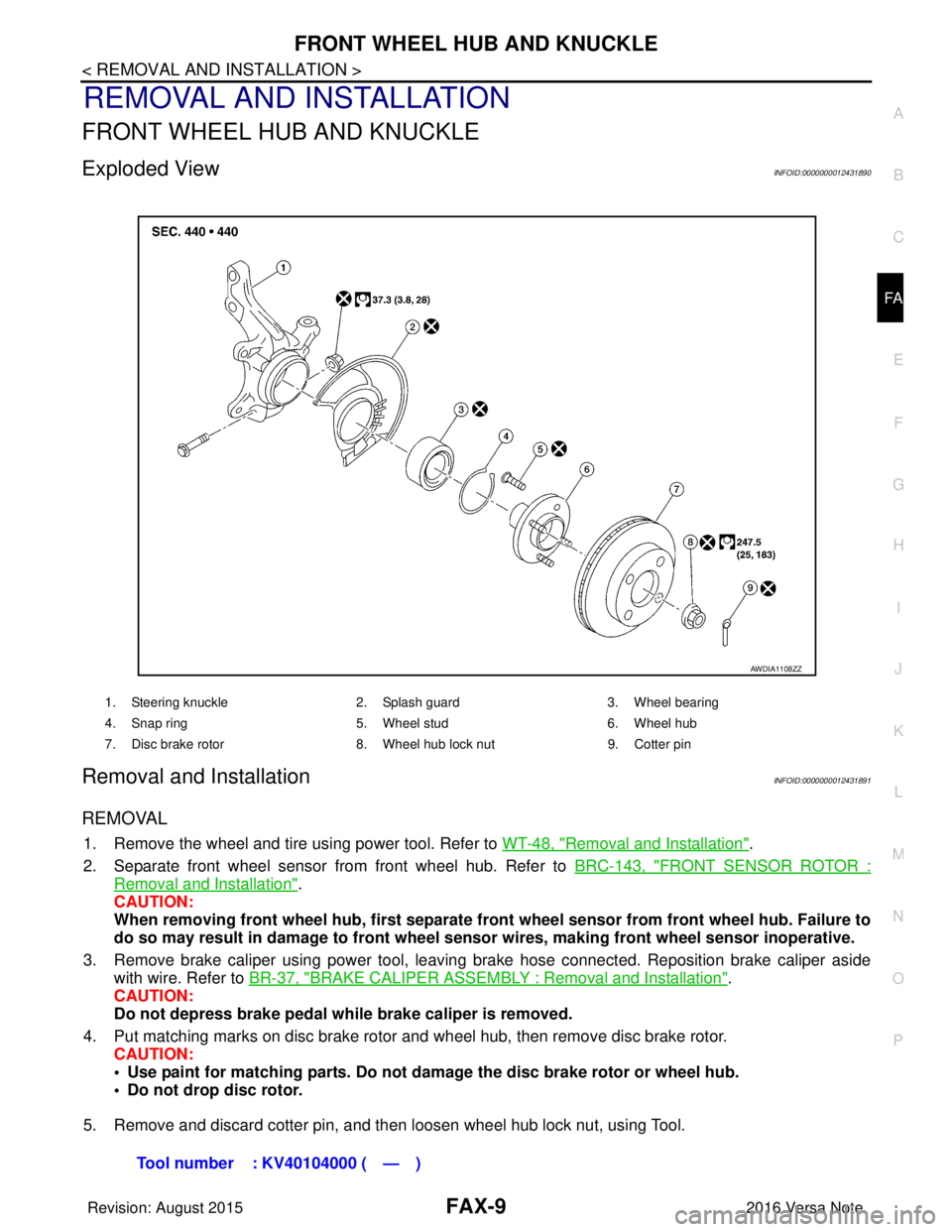
Exploded ViewINFOID:0000000012431890
Removal and InstallationINFOID:0000000012431891
REMOVAL
1. Remove the wheel and tire using power tool. Refer to WT-48, "Removal and Installation".
2. Separate front wheel sensor from front wheel hub. Refer to BRC-143, "
FRONT SENSOR ROTOR :
Removal and Installation".
CAUTION:
When removing front wheel hub, first separate front wheel sensor from front wheel hub. Failure to
do so may result in damage to front wheel sensor wires, making front wheel sensor inoperative.
3. Remove brake caliper using power tool, leaving brake hose connected. Reposition brake caliper aside with wire. Refer to BR-37, "
BRAKE CALIPER ASSEMBLY : Removal and Installation".
CAUTION:
Do not depress brake pedal while brake caliper is removed.
4. Put matching marks on disc brake rotor and wheel hub, then remove disc brake rotor. CAUTION:
• Use paint for matching parts. Do not damage the disc brake rotor or wheel hub.
• Do not drop disc rotor.
5. Remove and discard cotter pin, and then loosen wheel hub lock nut, using Tool.
1. Steering knuckle 2. Splash guard3. Wheel bearing
4. Snap ring 5. Wheel stud6. Wheel hub
7. Disc brake rotor 8. Wheel hub lock nut9. Cotter pin
AWDIA1108ZZ
Tool number : KV40104000 ( — )
Revision: August 2015 2016 Versa Note
cardiagn.com
Page 1827 of 3641
FAX-10
< REMOVAL AND INSTALLATION >
FRONT WHEEL HUB AND KNUCKLE
6. Separate the drive shaft from the wheel hub by lightly tapping the end of the drive shaft using a suitable
tool and a wood block.
NOTE:
Use suitable puller if wheel hub and drive shaft cannot be separated after performing the above proce-
dure.
7. Remove wheel hub lock nut.
8. Remove the nut and separate the steering out er socket from steering knuckle. Refer to ST-14, "
Exploded
View".
9. Remove the nuts and bolts, then separate the steering knuckle from strut. Refer to FA X - 9 , "
Removal and
Installation".
10. Suspend the drive shaft with suitable wire. CAUTION:
• Do not place drive shaft joint at an extreme angle. Also be careful not to overextend slide joint.
• Do not allow drive shaft to hang down withou t support for joint sub-assembly, shaft and the
other parts.
11. Remove transverse link outer nut and bolt. Remove steering knuckle from transverse link.
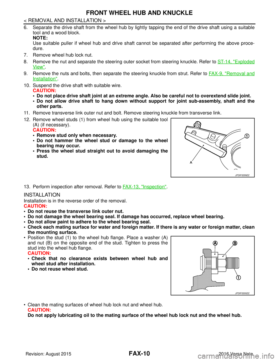
12. Remove wheel studs (1) from wheel hub using the suitable tool (A) (if necessary).
CAUTION:
• Remove stud only when necessary.
• Do not hammer the wheel stud or damage to the wheelbearing may occur.
• Press the wheel stud straight out to avoid damaging the stud.
13. Perform inspection after removal. Refer to FAX-13, "
Inspection".
INSTALLATION
Installation is in the reverse order of the removal.
CAUTION:
• Do not reuse the transverse link outer nut.
• Do not damage the wheel bearing seal. If damage has occurred, replace wheel bearing.
• Do not allow paint to adhere to the wheel bearing seal.
• Check each mating surface for water and foreign matter. If there is any water or foreign matter, clean
the mounting surface.
• Position the stud (1) to the wheel hub flange. Place a washer (A) and nut (B) on the opposite end of the stud. Tighten to press the
stud into the wheel hub flange.
CAUTION:
• Check that no clearance exists between wheel hub andwheel stud after installation.
• Do not reuse wheel stud.
• Clean the mating surfaces of wheel hub lock nut and wheel hub. CAUTION:
Do not apply lubricatin g oil to the mating surface of the wh eel hub lock nut and the wheel hub.
JPDIF0299ZZ
JPDIF0300ZZ
Revision: August 2015 2016 Versa Note
cardiagn.com
Page 1828 of 3641
FRONT WHEEL HUB AND KNUCKLEFAX-11
< REMOVAL AND INSTALLATION >
CEF
G H
I
J
K L
M A
B
FA X
N
O P
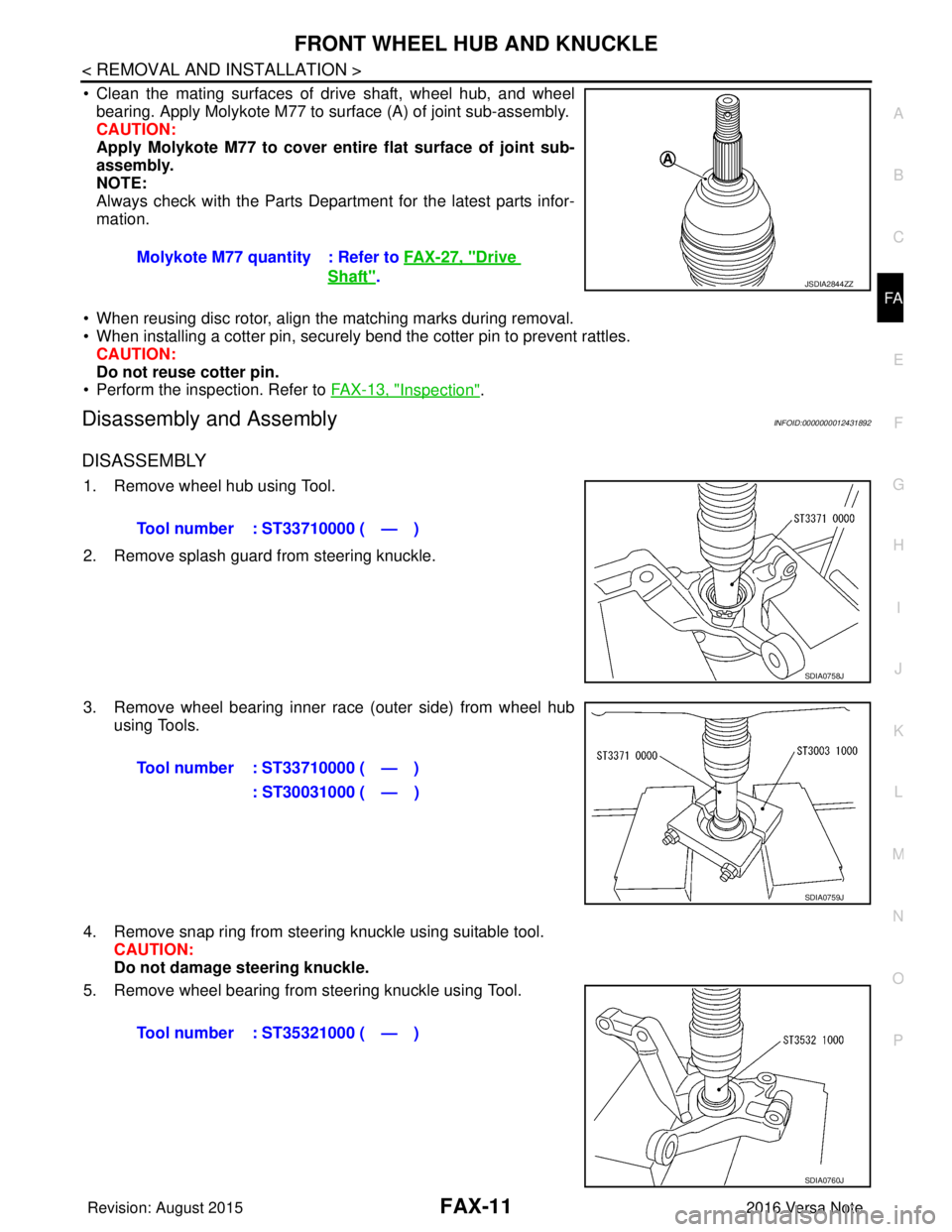
• Clean the mating surfaces of drive shaft, wheel hub, and wheel bearing. Apply Molykote M77 to surface (A) of joint sub-assembly.
CAUTION:
Apply Molykote M77 to cover en tire flat surface of joint sub-
assembly.
NOTE:
Always check with the Parts Department for the latest parts infor-
mation.
• When reusing disc rotor, align the matching marks during removal.
• When installing a cotter pin, securely bend the cotter pin to prevent rattles. CAUTION:
Do not reuse cotter pin.
• Perform the inspection. Refer to FAX-13, "
Inspection".
Disassembly and AssemblyINFOID:0000000012431892
DISASSEMBLY
1. Remove wheel hub using Tool.
2. Remove splash guard from steering knuckle.
3. Remove wheel bearing inner race (outer side) from wheel hub
using Tools.
4. Remove snap ring from steering knuckle using suitable tool. CAUTION:
Do not damage steering knuckle.
5. Remove wheel bearing from steering knuckle using Tool. Molykote M77 quantity : Refer to
FAX-27, "
Drive
Shaft".JSDIA2844ZZ
Tool number : ST33710000 ( — )
SDIA0758J
Tool number : ST33710000 ( — )
: ST30031000 ( — )
SDIA0759J
Tool number : ST35321000 ( — )
SDIA0760J
Revision: August 2015 2016 Versa Note
cardiagn.com
Page 1829 of 3641
FAX-12
< REMOVAL AND INSTALLATION >
FRONT WHEEL HUB AND KNUCKLE
6. Perform inspection after disassembly. Refer to FAX-13, "Inspection".
ASSEMBLY
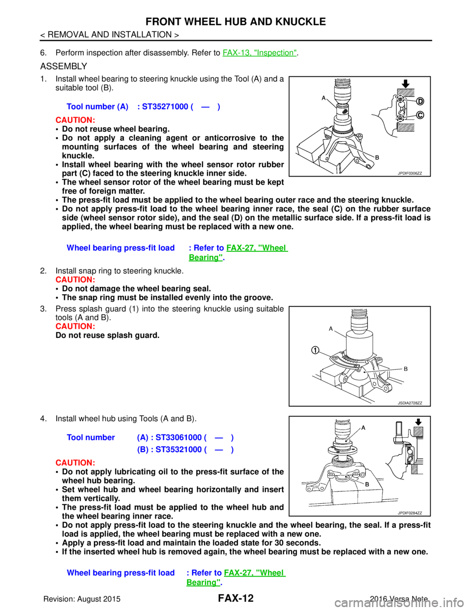
1. Install wheel bearing to steering knuckle using the Tool (A) and a
suitable tool (B).
CAUTION:
• Do not reuse wheel bearing.
• Do not apply a cleaning agen t or anticorrosive to the
mounting surfaces of the wh eel bearing and steering
knuckle.
• Install wheel bearing with the wheel sensor rotor rubber
part (C) faced to the st eering knuckle inner side.
• The wheel sensor rotor of th e wheel bearing must be kept
free of foreign matter.
• The press-fit load must be applied to the wh eel bearing outer race and the steering knuckle.
• Do not apply press-fit load to the wheel beari ng inner race, the seal (C) on the rubber surface
side (wheel sensor rotor side), and the seal (D) on the metallic surface side. If a press-fit load is
applied, the wheel bearing must be replaced with a new one.
2. Install snap ring to steering knuckle. CAUTION:
• Do not damage the wheel bearing seal.
• The snap ring must be inst alled evenly into the groove.
3. Press splash guard (1) into the steering knuckle using suitable tools (A and B).
CAUTION:
Do not reuse splash guard.
4. Install wheel hub using Tools (A and B). CAUTION:
• Do not apply lubri cating oil to the press-fit surface of the
wheel hub bearing.
• Set wheel hub and wheel bearing horizontally and insert them vertically.
• The press-fit load must be applied to the wheel hub and
the wheel bearing inner race.
• Do not apply press-fit load to the steering knuckle and the wheel b earing, the seal. If a press-fit
load is applied, the wheel bearin g must be replaced with a new one.
• Apply a press-fit load and maintain the loaded state for 30 seconds.
• If the inserted wheel hub is removed again, the wheel bearing must be replaced with a new one.
Tool number (A) : ST35271000 ( — )
Wheel bearing press-fit load : Refer to
FAX-27, "
Wheel
Bearing".
JPDIF0306ZZ
JSDIA2728ZZ
Tool number (A) : ST33061000 ( — )
(B) : ST35321000 ( — )
Wheel bearing press-fit load : Refer to FAX-27, "
Wheel
Bearing".
JPDIF0284ZZ
Revision: August 2015 2016 Versa Note
cardiagn.com