2016 NISSAN NOTE steering wheel
[x] Cancel search: steering wheelPage 1855 of 3641
FSU-10
< REMOVAL AND INSTALLATION >
TRANSVERSE LINK
TRANSVERSE LINK
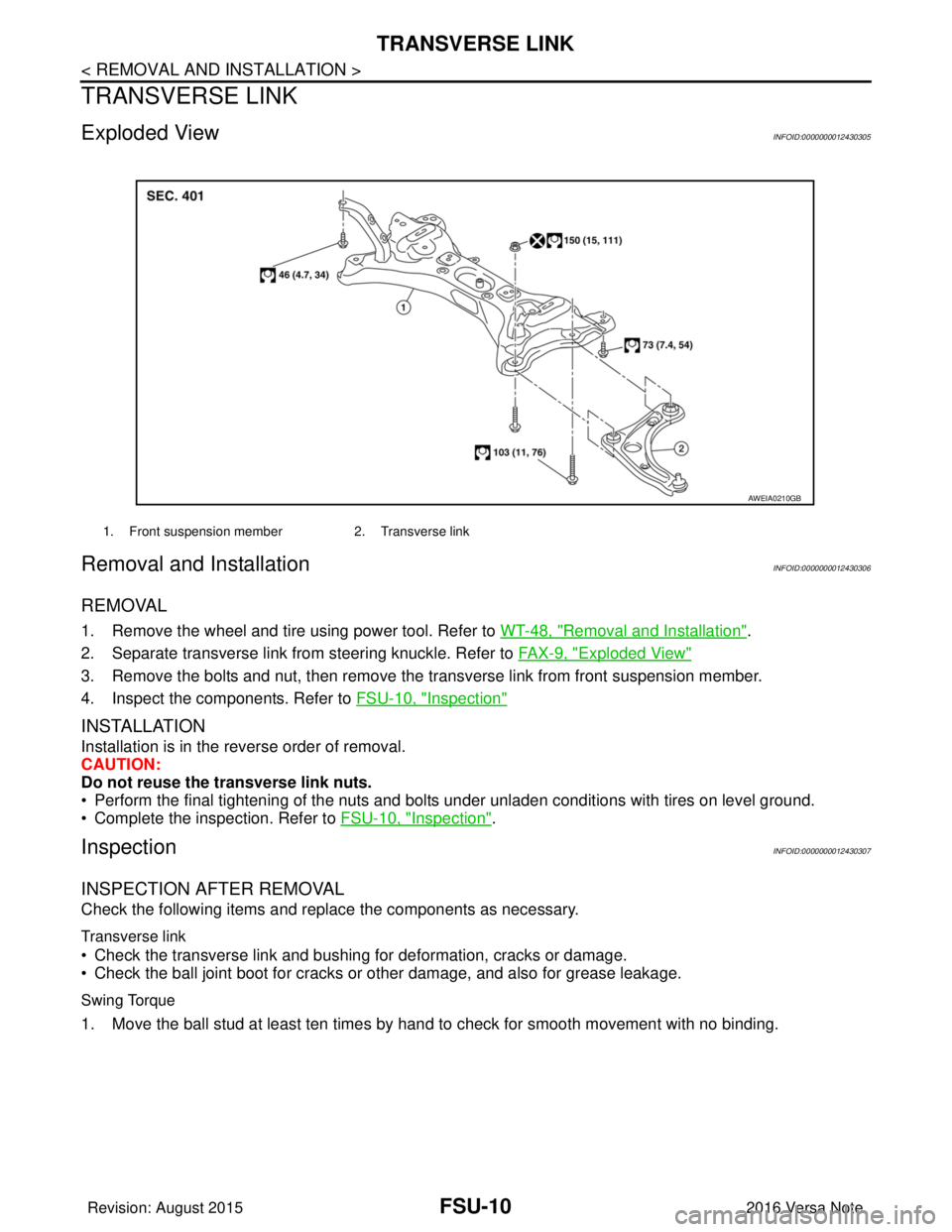
Exploded ViewINFOID:0000000012430305
Removal and InstallationINFOID:0000000012430306
REMOVAL
1. Remove the wheel and tire using power tool. Refer to WT-48, "Removal and Installation".
2. Separate transverse link from steering knuckle. Refer to FA X - 9 , "
Exploded View"
3. Remove the bolts and nut, then remove the transverse link from front suspension member.
4. Inspect the components. Refer to FSU-10, "
Inspection"
INSTALLATION
Installation is in the reverse order of removal.
CAUTION:
Do not reuse the transverse link nuts.
• Perform the final tightening of the nuts and bolts under unladen conditions with tires on level ground.
• Complete the inspection. Refer to FSU-10, "
Inspection".
InspectionINFOID:0000000012430307
INSPECTION AFTER REMOVAL
Check the following items and replace the components as necessary.
Transverse link
• Check the transverse link and bushing for deformation, cracks or damage.
• Check the ball joint boot for cracks or other damage, and also for grease leakage.
Swing Torque
1. Move the ball stud at least ten times by hand to check for smooth movement with no binding.
1. Front suspension member2. Transverse link
AWEIA0210GB
Revision: August 2015 2016 Versa Note
cardiagn.com
Page 1856 of 3641
TRANSVERSE LINKFSU-11
< REMOVAL AND INSTALLATION >
C
DF
G H
I
J
K L
M A
B
FSU
N
O P
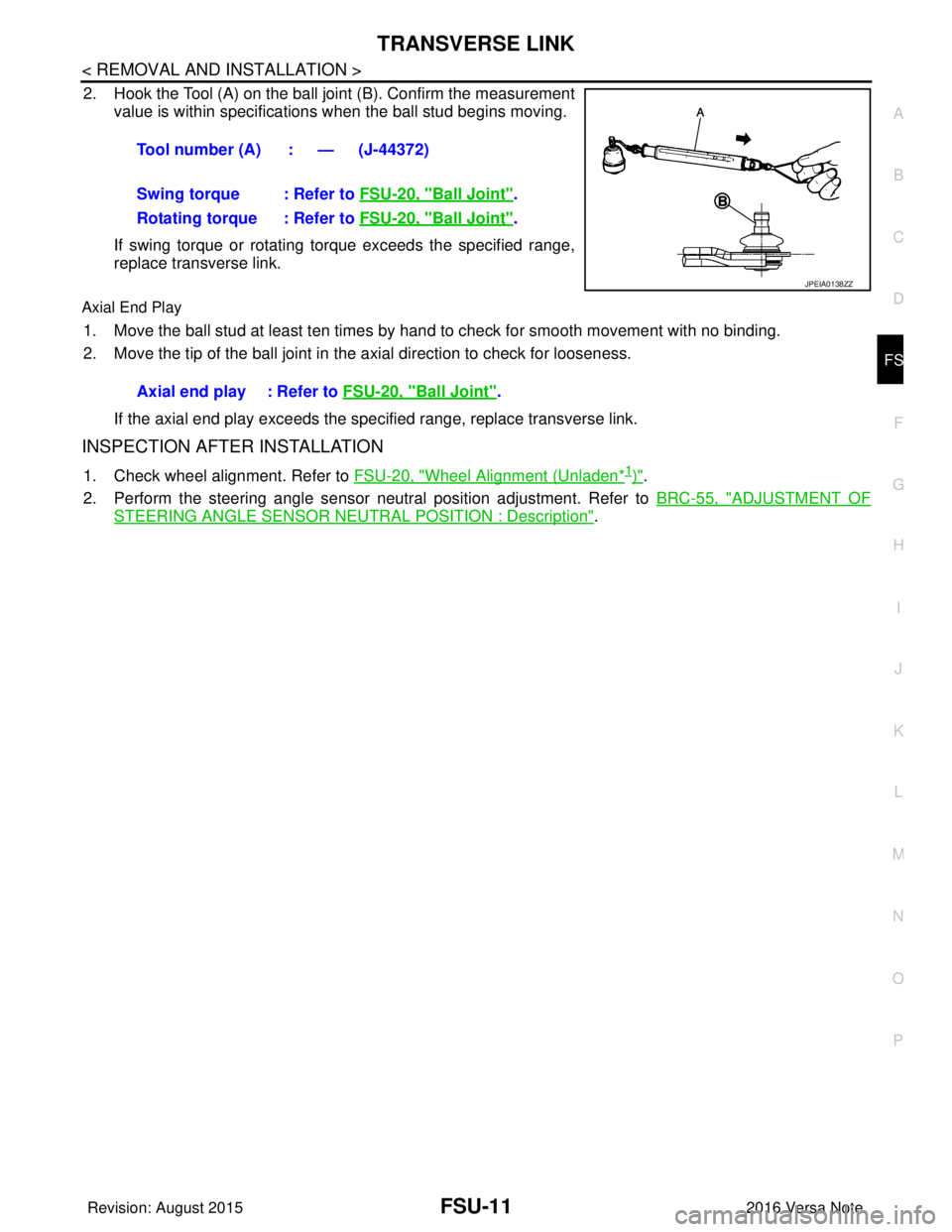
2. Hook the Tool (A) on the ball joint (B). Confirm the measurement value is within specifications when the ball stud begins moving.
If swing torque or rotating torque exceeds the specified range,
replace transverse link.
Axial End Play
1. Move the ball stud at least ten times by hand to check for smooth movement with no binding.
2. Move the tip of the ball joint in the axial direction to check for looseness.
If the axial end play exceeds the specified range, replace transverse link.
INSPECTION AFTER INSTALLATION
1. Check wheel alignment. Refer to FSU-20, "Wheel Alignment (Unladen*1)".
2. Perform the steering angle sensor neutral position adjustment. Refer to BRC-55, "
ADJUSTMENT OF
STEERING ANGLE SENSOR NEUTRAL POSITION : Description".
Tool number (A) : — (J-44372)
Swing torque : Refer to
FSU-20, "
Ball Joint".
Rotating torque : Refer to FSU-20, "
Ball Joint".
JPEIA0138ZZ
Axial end play : Refer to FSU-20, "Ball Joint".
Revision: August 2015 2016 Versa Note
cardiagn.com
Page 1858 of 3641
FRONT STABILIZERFSU-13
< REMOVAL AND INSTALLATION >
C
DF
G H
I
J
K L
M A
B
FSU
N
O P
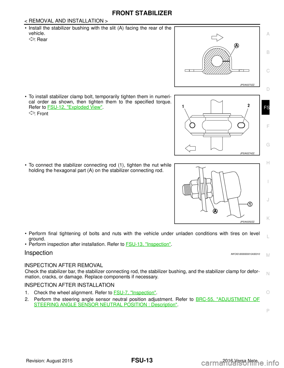
• Install the stabilizer bushing with the slit (A) facing the rear of the vehicle.
: Rear
• To install stabilizer clamp bolt, temporarily tighten them in numeri- cal order as shown, then tighten them to the specified torque.
Refer to FSU-12, "
Exploded View".
: Front
• To connect the stabilizer connecting rod (1), tighten the nut while holding the hexagonal part (A) on the stabilizer connecting rod.
• Perform final tightening of bolts and nuts with the vehicle under unladen conditions with tires on level ground.
• Perform inspection after installation. Refer to FSU-13, "
Inspection".
InspectionINFOID:0000000012430310
INSPECTION AFTER REMOVAL
Check the stabilizer bar, the stabilizer connecting rod, t he stabilizer bushing, and the stabilizer clamp for defor-
mation, cracks, or damage. Replace components if necessary.
INSPECTION AFTER INSTALLATION
1. Check the wheel alignment. Refer to FSU-7, "Inspection".
2. Perform the steering angle sensor neutral position adjustment. Refer to BRC-55, "
ADJUSTMENT OF
STEERING ANGLE SENSOR NEUTRAL POSITION : Description".
JPEIA0273ZZ
JPEIA0274ZZ
JPEIA0252ZZ
Revision: August 2015 2016 Versa Note
cardiagn.com
Page 1859 of 3641
FSU-14
< UNIT REMOVAL AND INSTALLATION >
FRONT SUSPENSION MEMBER
UNIT REMOVAL AND INSTALLATION
FRONT SUSPENSION MEMBER
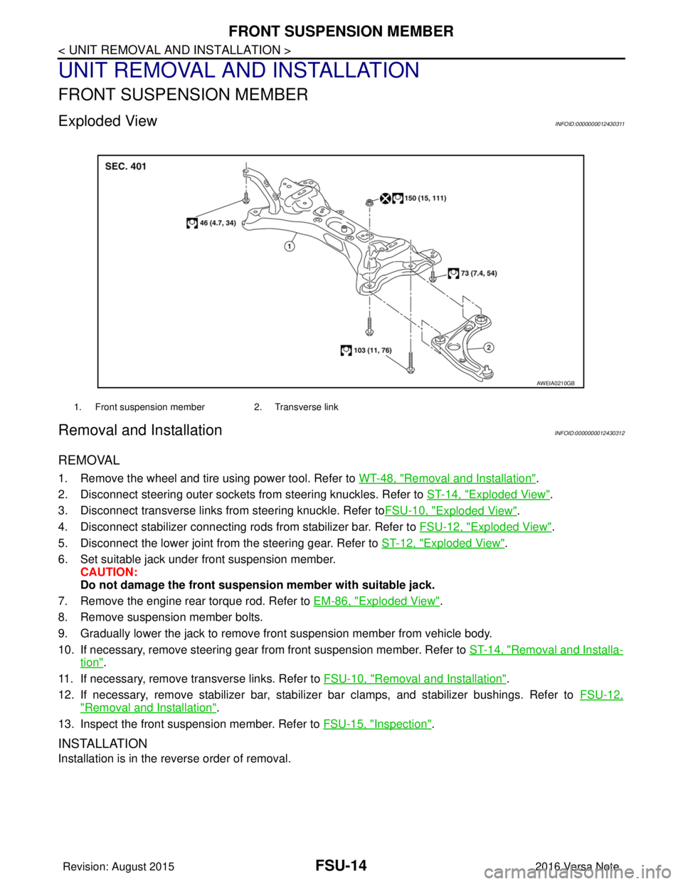
Exploded ViewINFOID:0000000012430311
Removal and InstallationINFOID:0000000012430312
REMOVAL
1. Remove the wheel and tire using power tool. Refer to WT-48, "Removal and Installation".
2. Disconnect steering outer sockets from steering knuckles. Refer to ST-14, "
Exploded View".
3. Disconnect transverse links from steering knuckle. Refer to FSU-10, "
Exploded View".
4. Disconnect stabilizer connecting rods from stabilizer bar. Refer to FSU-12, "
Exploded View".
5. Disconnect the lower joint from the steering gear. Refer to ST-12, "
Exploded View".
6. Set suitable jack under front suspension member. CAUTION:
Do not damage the front suspensi on member with suitable jack.
7. Remove the engine rear torque rod. Refer to EM-86, "
Exploded View".
8. Remove suspension member bolts.
9. Gradually lower the jack to remove front suspension member from vehicle body.
10. If necessary, remove steering gear from front suspension member. Refer to ST-14, "
Removal and Installa-
tion".
11. If necessary, remove transverse links. Refer to FSU-10, "
Removal and Installation".
12. If necessary, remove stabilizer bar, stabilizer bar clamps, and stabilizer bushings. Refer to FSU-12,
"Removal and Installation".
13. Inspect the front suspension member. Refer to FSU-15, "
Inspection".
INSTALLATION
Installation is in the reverse order of removal.
1. Front suspension member2. Transverse link
AWEIA0210GB
Revision: August 2015 2016 Versa Note
cardiagn.com
Page 1860 of 3641
FRONT SUSPENSION MEMBERFSU-15
< UNIT REMOVAL AND INSTALLATION >
C
DF
G H
I
J
K L
M A
B
FSU
N
O P
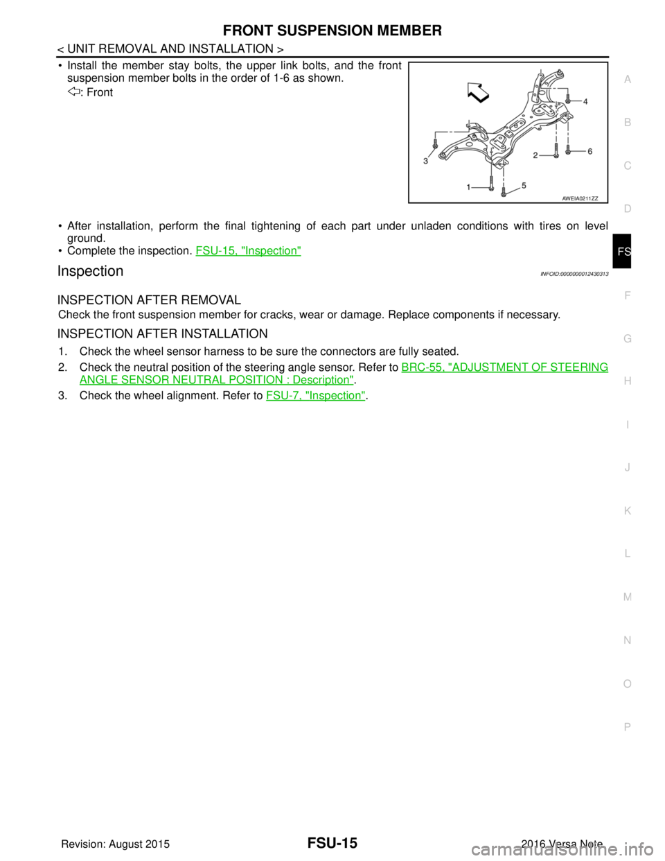
• Install the member stay bolts, the upper link bolts, and the front suspension member bolts in the order of 1-6 as shown.
: Front
• After installation, perform the final tightening of each part under unladen conditions with tires on level
ground.
• Complete the inspection. FSU-15, "
Inspection"
InspectionINFOID:0000000012430313
INSPECTION AFTER REMOVAL
Check the front suspension member for cracks, wear or damage. Replace components if necessary.
INSPECTION AFTER INSTALLATION
1. Check the wheel sensor harness to be sure the connectors are fully seated.
2. Check the neutral position of the steering angle sensor. Refer to BRC-55, "
ADJUSTMENT OF STEERING
ANGLE SENSOR NEUTRAL POSITION : Description".
3. Check the wheel alignment. Refer to FSU-7, "
Inspection".
AWEIA0211ZZ
Revision: August 2015 2016 Versa Note
cardiagn.com
Page 1864 of 3641
FRONT COIL SPRING AND STRUTFSU-19
< UNIT DISASSEMBLY AND ASSEMBLY >
C
DF
G H
I
J
K L
M A
B
FSU
N
O P
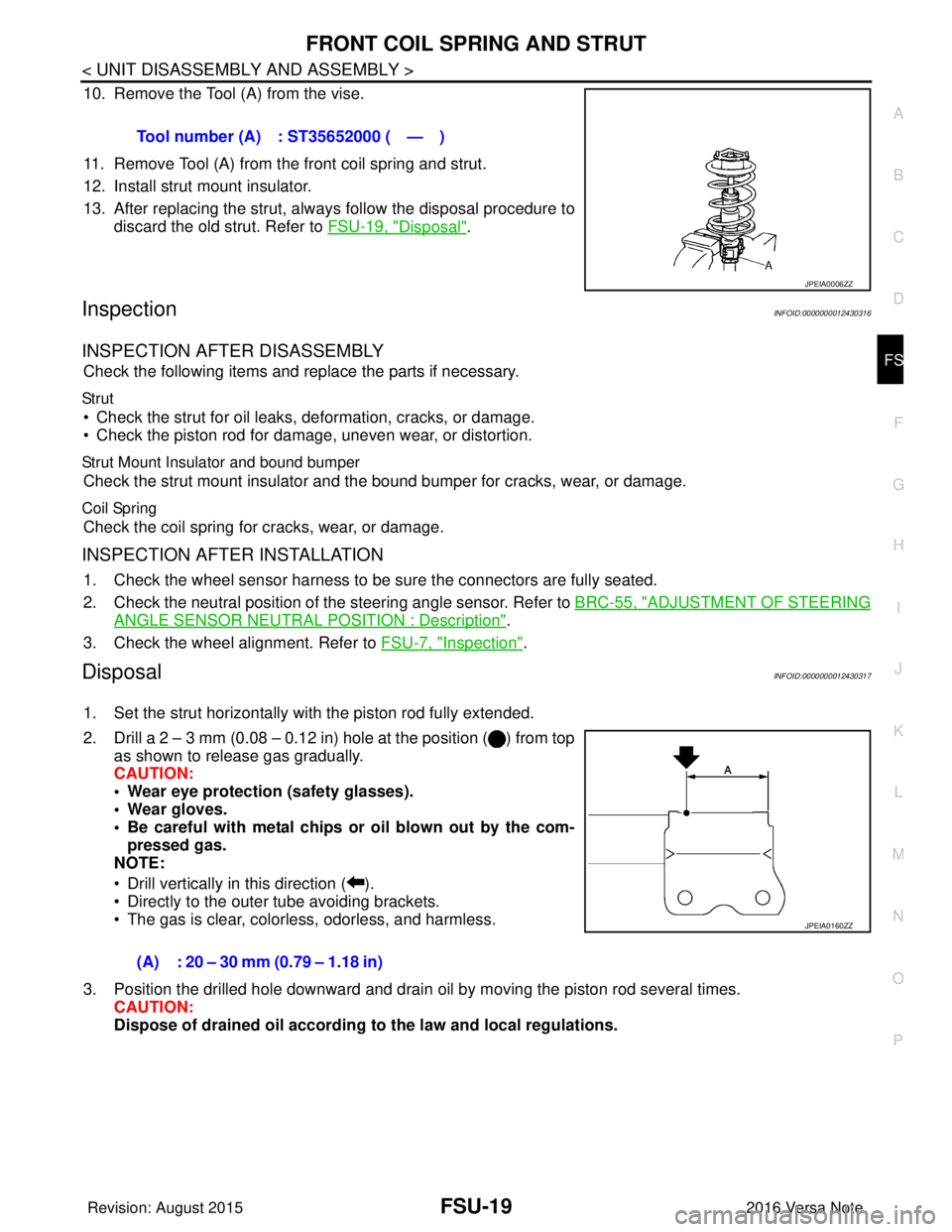
10. Remove the Tool (A) from the vise.
11. Remove Tool (A) from the front coil spring and strut.
12. Install strut mount insulator.
13. After replacing the strut, always follow the disposal procedure to discard the old strut. Refer to FSU-19, "
Disposal".
InspectionINFOID:0000000012430316
INSPECTION AFTER DISASSEMBLY
Check the following items and replace the parts if necessary.
Str ut
• Check the strut for oil leaks, deformation, cracks, or damage.
• Check the piston rod for damage, uneven wear, or distortion.
Strut Mount Insulator and bound bumper
Check the strut mount insulator and t he bound bumper for cracks, wear, or damage.
Coil Spring
Check the coil spring for cracks, wear, or damage.
INSPECTION AFTER INSTALLATION
1. Check the wheel sensor harness to be sure the connectors are fully seated.
2. Check the neutral position of the steering angle sensor. Refer to BRC-55, "
ADJUSTMENT OF STEERING
ANGLE SENSOR NEUTRAL POSITION : Description".
3. Check the wheel alignment. Refer to FSU-7, "
Inspection".
DisposalINFOID:0000000012430317
1. Set the strut horizontally with the piston rod fully extended.
2. Drill a 2 – 3 mm (0.08 – 0.12 in) hole at the position ( ) from top
as shown to release gas gradually.
CAUTION:
• Wear eye protection (safety glasses).
• Wear gloves.
• Be careful with metal chips or oil blown out by the com-
pressed gas.
NOTE:
• Drill vertically in this direction ( ).
• Directly to the outer tube avoiding brackets.
• The gas is clear, colorless, odorless, and harmless.
3. Position the drilled hole downward and drain oil by moving the piston rod several times. CAUTION:
Dispose of drained oil according to the law and local regulations.
Tool number (A) : ST35652000 ( — )
JPEIA0006ZZ
(A) : 20 – 30 mm (0.79 – 1.18 in)
JPEIA0160ZZ
Revision: August 2015
2016 Versa Note
cardiagn.com
Page 1919 of 3641
TOW TRUCK TOWINGGI-31
< PRECAUTION >
C
DE
F
G H
I
J
K L
M B
GI
N
O PTOW TRUCK TOWING
To w T r u c k To w i n gINFOID:0000000012433173
CAUTION:
• Never tow a CVT model with the rear wheels raised and the front wheels on the ground. This may
cause serious and expensive damage to the transaxle. If it is necessary to tow the vehicle with the
rear wheels raised, always use towin g dollies under the front wheels.
• Never tow a CVT model from the rear (that is b ackward) with four wheels on the ground. This may
cause serious and expensive damage to the transaxle.
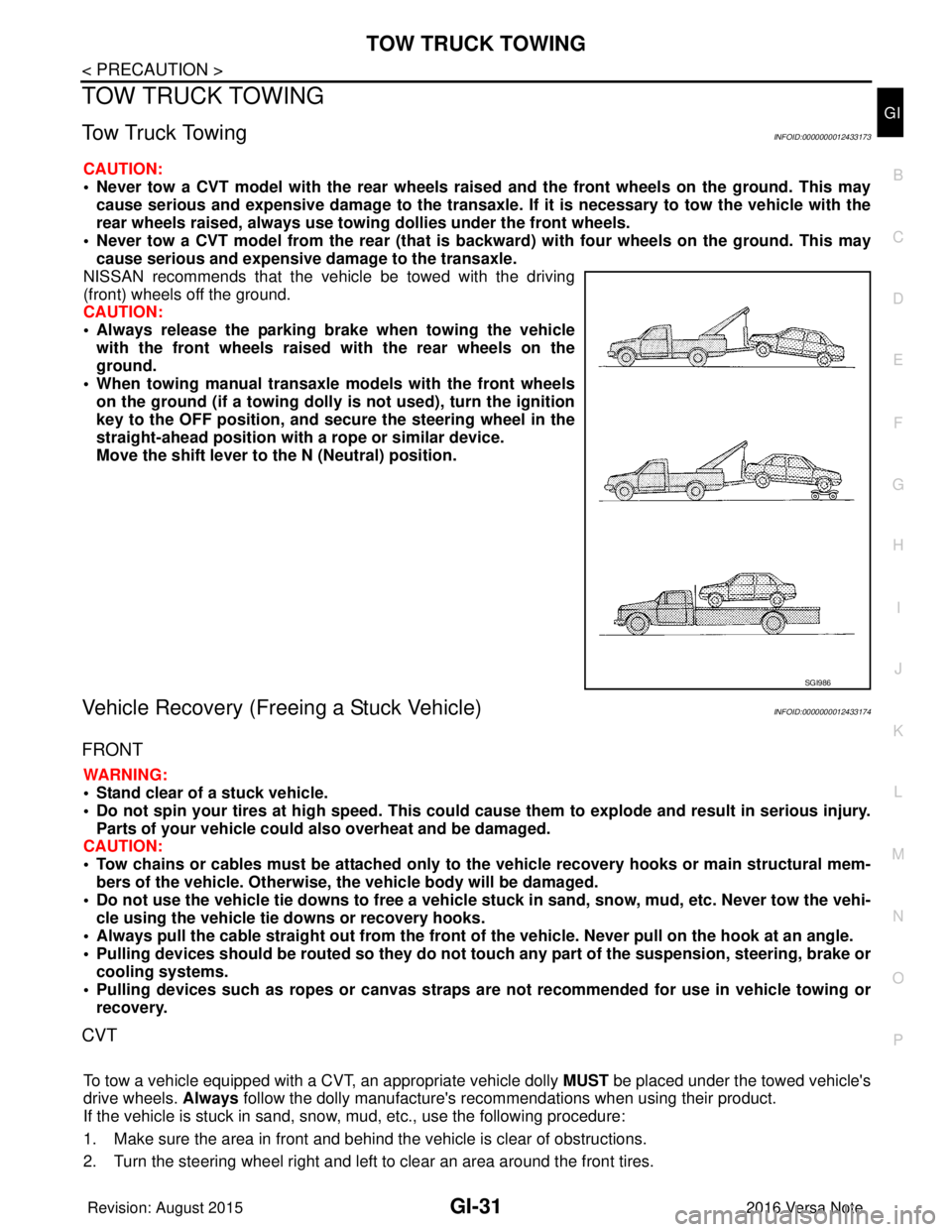
NISSAN recommends that the vehicle be towed with the driving
(front) wheels off the ground.
CAUTION:
• Always release the parking br ake when towing the vehicle
with the front wheels raised with the rear wheels on the
ground.
• When towing manual transaxle models with the front wheels on the ground (if a towing dolly is not used), turn the ignition
key to the OFF position, and secu re the steering wheel in the
straight-ahead position with a rope or similar device.
Move the shift lever to th e N (Neutral) position.
Vehicle Recovery (Freeing a Stuck Vehicle)INFOID:0000000012433174
FRONT
WARNING:
• Stand clear of a stuck vehicle.
• Do not spin your tires at high speed. This could cause them to explode and result in serious injury.
Parts of your vehicle could also overheat and be damaged.
CAUTION:
• Tow chains or cables must be attached only to the vehicle recovery hooks or main structural mem-
bers of the vehicle. Otherwise, the vehicle body will be damaged.
• Do not use the vehicle tie downs to free a vehicle stuck in sand, snow, mud, etc. Never tow the vehi-
cle using the vehicle tie downs or recovery hooks.
• Always pull the cable straight out from the front of the vehicle. Never pull on the hook at an angle.
• Pulling devices should be routed so they do not touch any part of the suspension, steering, brake or
cooling systems.
• Pulling devices such as ropes or canvas straps ar e not recommended for use in vehicle towing or
recovery.
CVT
To tow a vehicle equipped with a CVT, an appropriate vehicle dolly MUST be placed under the towed vehicle's
drive wheels. Always follow the dolly manufacture's re commendations when using their product.
If the vehicle is stuck in sand, snow , mud, etc., use the following procedure:
1. Make sure the area in front and behind the vehicle is clear of obstructions.
2. Turn the steering wheel right and left to clear an area around the front tires.
SGI986
Revision: August 2015 2016 Versa Note
cardiagn.com
Page 2083 of 3641
INSTRUMENT PANEL ASSEMBLYIP-15
< REMOVAL AND INSTALLATION >
C
DE
F
G H
I
K L
M A
B
IP
N
O P
Removal and InstallationINFOID:0000000012430778
CAUTION:
• Be careful not to scratch instrument panel pad or other parts.
• Before servicing, turn the ignition switch off, disconnect both battery terminals and wait at least
three minutes.
• Do not tamper with or force air bag lid open, as this may adversely affect air bag performance.
REMOVAL
1. Disconnect the negative and positive battery terminals, then wait at least three minutes. Refer to PG-70,
"Removal and Installation (Battery)".
2. Remove front pillar finishers (LH/RH). Refer to INT-21, "
FRONT PILLAR FINISHER : Removal and Instal-
lation".
3. Remove dash side finishers (LH/RH). Refer to INT-24, "
DASH SIDE FINISHER : Removal and Installa-
tion".
4. Partially remove front body side welts (LH/RH). Refer to INT-21, "
Exploded View".
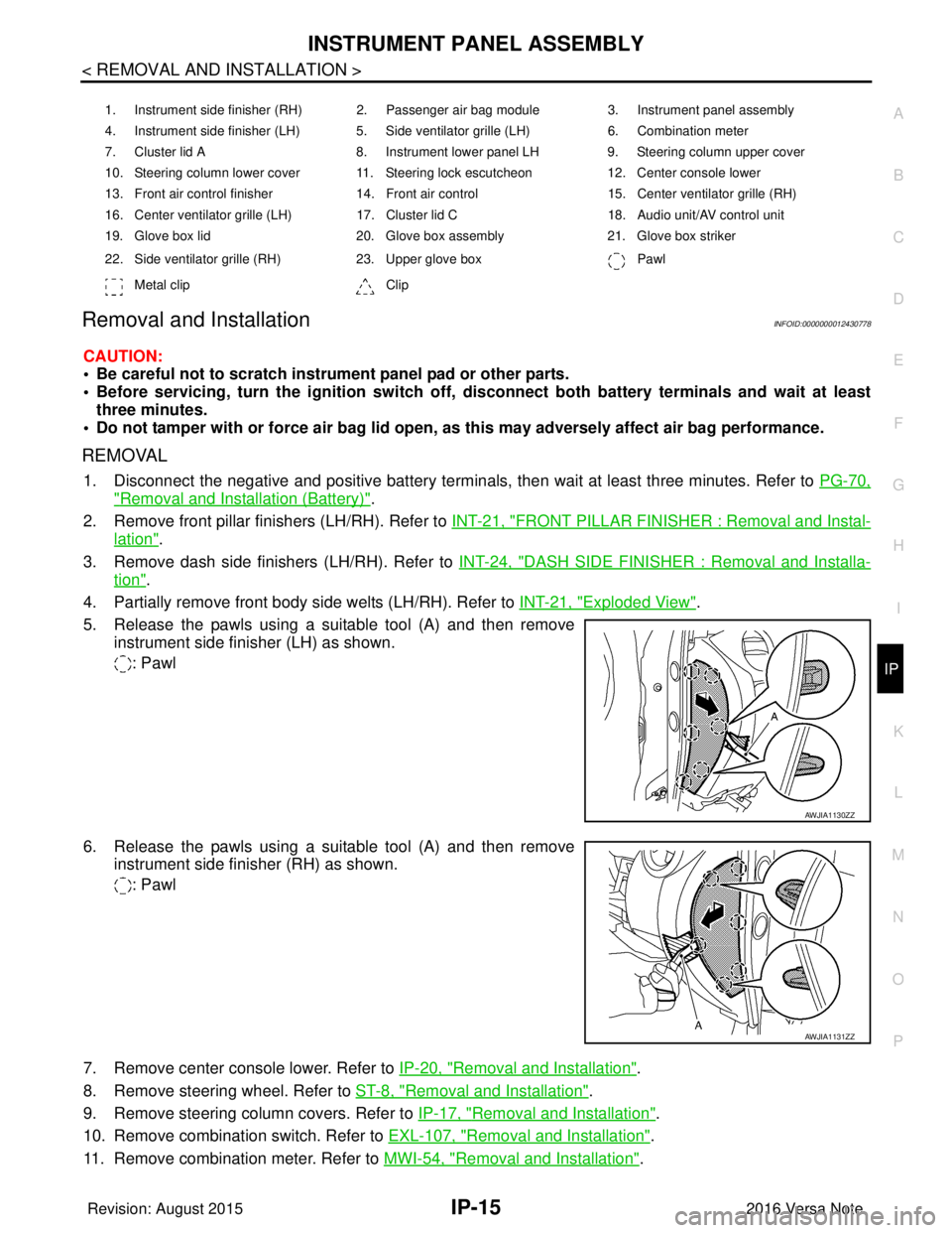
5. Release the pawls using a suitable tool (A) and then remove instrument side finisher (LH) as shown.
: Pawl
6. Release the pawls using a suitable tool (A) and then remove instrument side finisher (RH) as shown.
: Pawl
7. Remove center console lower. Refer to IP-20, "
Removal and Installation".
8. Remove steering wheel. Refer to ST-8, "
Removal and Installation".
9. Remove steering column covers. Refer to IP-17, "
Removal and Installation".
10. Remove combination switch. Refer to EXL-107, "
Removal and Installation".
11. Remove combination meter. Refer to MWI-54, "
Removal and Installation".
1. Instrument side finisher (RH) 2. Passenger air bag module 3. Instrument panel assembly
4. Instrument side finisher (LH) 5. Side ventilator grille (LH) 6. Combination meter
7. Cluster lid A 8. Instrument lower panel LH9. Steering column upper cover
10. Steering column lower cover 11. Steering lock escutcheon 12. Center console lower
13. Front air control finisher 14. Front air control15. Center ventilator grille (RH)
16. Center ventilator grille (LH) 17. Cluster lid C 18. Audio unit/AV control unit
19. Glove box lid 20. Glove box assembly21. Glove box striker
22. Side ventilator grille (RH) 23. Upper glove box Pawl
Metal clip Clip
AWJIA1130ZZ
AWJIA1131ZZ
Revision: August 2015 2016 Versa Note
cardiagn.com