2016 NISSAN NOTE heating
[x] Cancel search: heatingPage 400 of 3641

BRM-1
BODY EXTERIOR, DOORS, ROOF & VEHICLE SECURITY
C
DE
F
G H
I
J
L
M
SECTION BRM
A
B
BRM
N
O P
CONTENTS
BODY REPAIR
VEHICLE INFORMATION ... ..........................2
BODY EXTERIOR PAINT COLOR ................ .....2
Body Exterior Paint Color ................................. ......2
PRECAUTION ...............................................3
PRECAUTIONS .............................................. .....3
Precaution for Supplemental Restraint System
(SRS) "AIR BAG" and "SEAT BELT PRE-TEN-
SIONER" ............................................................. ......
3
Precaution for Heating Metal .....................................3
HANDLING PRECAUTIONS FOR PLASTICS .....4
Precautions For Plastics .................................... ......4
PRECAUTIONS IN REPAIRING HIGH
STRENGTH STEEL .............................................
8
High Strength Steel (HSS) ................................ ......8
Handling of Ultra High Strength Steel Plate Parts ....10
PREPARATION ...........................................11
REPAIRING MATERIAL ................................ ....11
Foam Repair ....................................................... ....11
BODY COMPONENT PARTS ............................12
Underbody Component Parts ............................ ....12
Body Component Parts ...........................................14
REMOVAL AND INSTALLATION ...............16
CORROSION PROTECTION .............................16
Description ........................................................... ....16
Anti-Corrosive Wax .................................................16
Undercoating ...........................................................17
BODY SEALING ...............................................19
Description ...............................................................19
REPLACEMENT OPERATIONS .......................22
Description ...............................................................22
Hoodledge ...............................................................25
Front Side Member ..................................................27
Front Pillar ..............................................................28
Dash Side ................................................................31
Center Pillar .............................................................32
Roof .........................................................................35
Outer Sill .................................................................36
Rear Fender ............................................................37
Rear Panel ..............................................................38
Rear Floor Rear .....................................................39
Rear Side Member Extension ...............................40
SERVICE DATA AND SPECIFICATIONS
(SDS) ............... .......................................... ...
41
BODY ALIGNMENT ..........................................41
Body Center Marks ............................................ ....41
Description ...............................................................42
Engine Compartment ..............................................42
Underbody ...............................................................44
Passenger Compartment ........................................47
Rear End Panel .......................................................48
Revision: August 2015 2016 Versa Note
cardiagn.com
Page 402 of 3641

PRECAUTIONSBRM-3
< PRECAUTION >
C
DE
F
G H
I
J
L
M A
B
BRM
N
O P
PRECAUTION
PRECAUTIONS
Precaution for Supplemental Restraint System (SRS) "AIR BAG" and "SEAT BELT
PRE-TENSIONER"
INFOID:0000000012562862
The Supplemental Restraint System such as “AIR BAG” and “SEAT BELT PRE-TENSIONER”, used along
with a front seat belt, helps to reduce the risk or severi ty of injury to the driver and front passenger for certain
types of collision. Information necessary to service the system safely is included in the SR and SB section of
this Service Manual.
WARNING:
• To avoid rendering the SRS inoper ative, which could increase the risk of personal injury or death in
the event of a collision which would result in air bag inflation, all maintenance must be performed by
an authorized NISSAN/INFINITI dealer.
• Improper maintenance, including in correct removal and installation of the SRS, can lead to personal
injury caused by unintentional act ivation of the system. For removal of Spiral Cable and Air Bag
Module, see the SR section.
• Do not use electrical test equipm ent on any circuit related to the SRS unless instructed to in this
Service Manual. SRS wiring harnesses can be identi fied by yellow and/or orange harnesses or har-
ness connectors.
PRECAUTIONS WHEN USING POWER TOOLS (AIR OR ELECTRIC) AND HAMMERS
WARNING:
• When working near the Airbag Diagnosis Sensor Un it or other Airbag System sensors with the Igni-
tion ON or engine running, DO NOT use air or el ectric power tools or strike near the sensor(s) with a
hammer. Heavy vibration could activate the sensor( s) and deploy the air bag(s), possibly causing
serious injury.
• When using air or electric power tools or hammers, always switch the Ignition OFF, disconnect the
battery and wait at least three mi nutes before performing any service.
Precaution for Heating MetalINFOID:0000000012430791
• Normal Steel (coated and non-coated)
390 MPa - 590MPa
• High Tensile (coated and non-coated) above 590 MPa
• Maximum temperature for heating both steel types is: 550 degrees Celsius
Revision: August 2015 2016 Versa Note
cardiagn.com
Page 407 of 3641

BRM-8
< PRECAUTION >
PRECAUTIONS IN REPAIRING HIGH STRENGTH STEEL
PRECAUTIONS IN REPAIRING HIGH STRENGTH STEEL
High Strength Steel (HSS)INFOID:0000000012430793
High strength steel is used for body panels in order to reduce vehicle weight.
Accordingly, precautions in repairing automotive bodies made of high strength steel are described below:
SP130 is the most commonly used HSS.
Read the following precautions when repairing HSS:
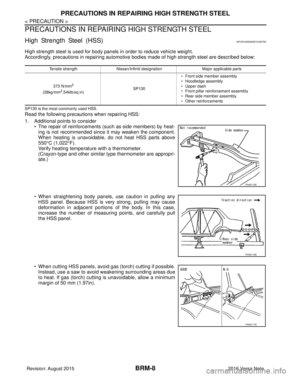
1. Additional points to consider
• The repair of reinforcements (such as side members) by heat-
ing is not recommended since it may weaken the component.
When heating is unavoidable, do not heat HSS parts above
550° C (1,022° F).
Verify heating temperature with a thermometer.
(Crayon-type and other similar type thermometer are appropri-
ate.)
• When straightening body panels, use caution in pulling any HSS panel. Because HSS is very strong, pulling may cause
deformation in adjacent portions of the body. In this case,
increase the number of measuring points, and carefully pull
the HSS panel.
• When cutting HSS panels, avoid gas (torch) cutting if possible. Instead, use a saw to avoid weakening surrounding areas due
to heat. If gas (torch) cutting is unavoidable, allow a minimum
margin of 50 mm (1.97in).
Tensile strength Nissan/Infiniti designation Major applicable parts
373 N/mm
2
(38kg/mm2,54klb/sq in) SP130• Front side member assembly
• Hoodledge assembly
• Upper dash
• Front pillar rein
forcement assembly
• Rear side member assembly
• Other reinforcements
PIIA0115E
PIIA0116E
PIIA0117E
Revision: August 2015 2016 Versa Note
cardiagn.com
Page 656 of 3641

COMPONENT PARTSDEF-5
< SYSTEM DESCRIPTION >
C
DE
F
G H
I
J
K
M A
B
DEF
N
O P
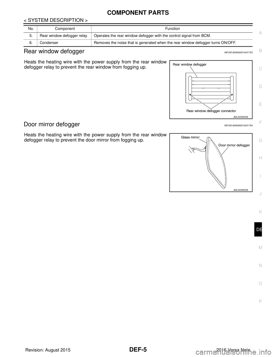
Rear window defoggerINFOID:0000000012431753
Heats the heating wire with the pow er supply from the rear window
defogger relay to prevent the rear window from fogging up.
Door mirror defoggerINFOID:0000000012431754
Heats the heating wire with the pow er supply from the rear window
defogger relay to prevent the door mirror from fogging up.
5. Rear window defogger relay Operates the rear window defogger with the control signal from BCM.
6. Condenser Removes the noise that is generated when the rear window defogger turns ON/OFF.
No.
Component Function
JMLIA2595GB
JMLIA2596GB
Revision: August 2015 2016 Versa Note
cardiagn.com
Page 675 of 3641

DEF-24
< DTC/CIRCUIT DIAGNOSIS >
REAR WINDOW DEFOGGER POWER SUPPLY AND GROUND CIRCUIT
REAR WINDOW DEFOGGER POWER SUPPLY AND GROUND CIRCUIT
DescriptionINFOID:0000000012431771
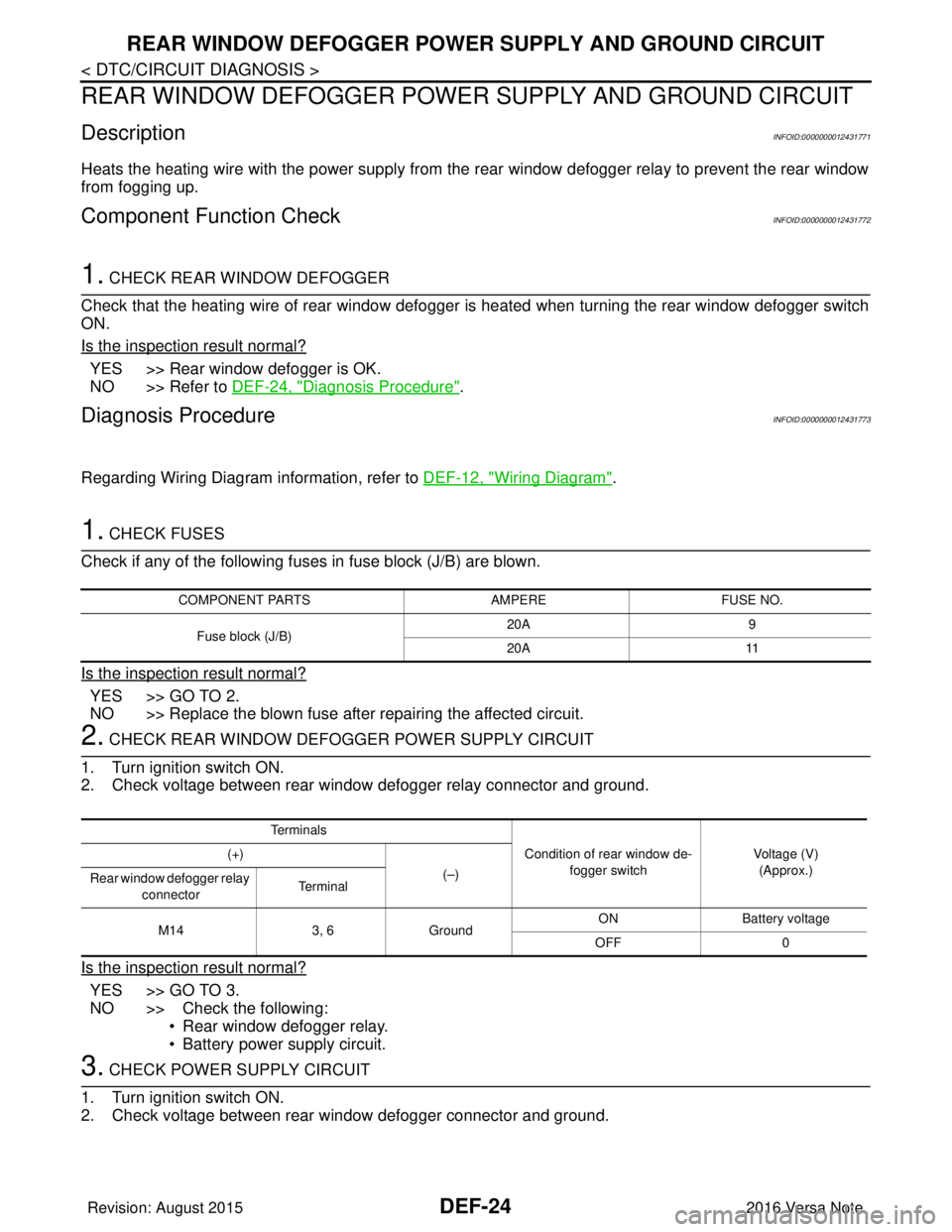
Heats the heating wire with the power supply from the rear window defogger relay to prevent the rear window
from fogging up.
Component Function CheckINFOID:0000000012431772
1. CHECK REAR WINDOW DEFOGGER
Check that the heating wire of rear window defogger is heated when turning the rear window defogger switch
ON.
Is the inspection result normal?
YES >> Rear window defogger is OK.
NO >> Refer to DEF-24, "
Diagnosis Procedure".
Diagnosis ProcedureINFOID:0000000012431773
Regarding Wiring Diagram information, refer to DEF-12, "Wiring Diagram".
1. CHECK FUSES
Check if any of the following fuses in fuse block (J/B) are blown.
Is the inspection result normal?
YES >> GO TO 2.
NO >> Replace the blown fuse after repairing the affected circuit.
2. CHECK REAR WINDOW DEFOGGER POWER SUPPLY CIRCUIT
1. Turn ignition switch ON.
2. Check voltage between rear window defogger relay connector and ground.
Is the inspection result normal?
YES >> GO TO 3.
NO >> Check the following: • Rear window defogger relay.
• Battery power supply circuit.
3. CHECK POWER SUPPLY CIRCUIT
1. Turn ignition switch ON.
2. Check voltage between rear window defogger connector and ground.
COMPONENT PARTS AMPEREFUSE NO.
Fuse block (J/B) 20A
9
20A 11
Te r m i n a l s
Condition of rear window de-fogger switch Voltage (V)
(Approx.)
(+)
(–)
Rear window defogger relay
connector Te r m i n a l
M14 3, 6Ground ON Battery
voltage
OFF 0
Revision: August 2015 2016 Versa Note
cardiagn.com
Page 677 of 3641

DEF-26
< DTC/CIRCUIT DIAGNOSIS >
DRIVER SIDE DOOR MIRROR DEFOGGER
DRIVER SIDE DOOR MIRROR DEFOGGER
DescriptionINFOID:0000000012431775
Heats the heating wire with the power supply from the rear window defogger relay to prevent the door mirror
from fogging up.
Component Function CheckINFOID:0000000012431776
1. CHECK DOOR MIRROR DEFOGGER LH
Check that heating wire of door mirror defogger LH is heated when turning the rear window defogger switch
ON.
Is the inspection result normal?
YES >> Door mirror defogger is OK.
NO >> Refer to DEF-26, "
Diagnosis Procedure".
Diagnosis ProcedureINFOID:0000000012431777
Regarding Wiring Diagram information, refer to DEF-12, "Wiring Diagram".
1. CHECK POWER SUPPLY CIRCUIT
1. Turn ignition switch OFF.
2. Disconnect door mirror LH.
3. Turn ignition switch ON.
4. Check voltage between door mirror LH connector and ground.
Is the inspection result normal?
YES >> GO TO 2.
NO >> Repair or replace harness.
2. CHECK GROUND CIRCUIT
1. Turn ignition switch OFF.
2. Check continuity between door mirror LH connector and ground.
Is the inspection result normal?
YES >> GO TO 3.
NO >> Repair or replace harness.
3. CHECK DOOR MIRROR DEFOGGER LH
Check door mirror defogger LH.
Refer to DEF-27, "
Component Inspection".
Is the inspection result normal?
YES >> GO TO 4.
NO >> Replace door mirror. Refer to MIR-15, "
Removal and Installation".
4. CHECK INTERMITTENT INCIDENT
Te r m i n a l s
Condition of rear window
defogger switch Voltage (V)
(Approx.)
(+)
(–)
Door mirror LH connector Terminal
D4 5Ground ON
Battery voltage
OFF 0
Door mirror LH connector Terminal
GroundContinuity
D4 4 Yes
Revision: August 2015 2016 Versa Note
cardiagn.com
Page 679 of 3641

DEF-28
< DTC/CIRCUIT DIAGNOSIS >
PASSENGER SIDE DOOR MIRROR DEFOGGER
PASSENGER SIDE DOOR MIRROR DEFOGGER
DescriptionINFOID:0000000012431779
Heats the heating wire with the power supply from the rear window defogger relay to prevent the door mirror
from fogging up.
Component Function CheckINFOID:0000000012431780
1.CHECK DOOR MIRROR DEFOGGER RH
Check that the heating wire of door mirror defogger RH is heated when turning the rear window defogger
switch ON.
Is the inspection result normal?
YES >> Door mirror defogger RH is OK.
NO >> Refer to DEF-28, "
Diagnosis Procedure".
Diagnosis ProcedureINFOID:0000000012431781
Regarding Wiring Diagram information, refer to DEF-12, "Wiring Diagram".
1. CHECK POWER SUPPLY CIRCUIT
1. Turn ignition switch OFF.
2. Disconnect door mirror RH.
3. Turn ignition switch ON.
4. Check voltage between door mirror RH connector and ground.
Is the inspection result normal?
YES >> GO TO 2.
NO >> Repair or replace harness.
2. CHECK GROUND CIRCUIT
1. Turn ignition switch OFF.
2. Check continuity between door mirror RH connector and ground.
Is the inspection result normal?
YES >> GO TO 3.
NO >> Repair or replace harness.
3. CHECK PASSENGER SIDE DOOR MIRROR DEFOGGER
Check door mirror defogger RH.
Refer to DEF-29, "
Component Inspection".
Is the inspection result normal?
YES >> GO TO 4.
NO >> Replace door mirror RH. Refer to MIR-17, "
Removal and Installation".
4. CHECK INTERMITTENT INCIDENT
Te r m i n a l s
Condition of rear window de-
fogger switch Voltage (V)
(Approx.)
(+)
(–)
Door mirror RH connector Terminal
D107 5Ground ON
Battery voltage
OFF 0
Door mirror RH connector Terminal
GroundContinuity
D107 4 Yes
Revision: August 2015 2016 Versa Note
cardiagn.com
Page 1327 of 3641
![NISSAN NOTE 2016 Service Repair Manual EC-200
< DTC/CIRCUIT DIAGNOSIS >[HR16DE]
P0116 ECT SENSOR
5. Check 1st trip DTC.
Is 1st trip DTC detected?
YES >> Proceed to
EC-200, "Diagnosis Procedure".
NO >> INSPECTION END
Component Function Che NISSAN NOTE 2016 Service Repair Manual EC-200
< DTC/CIRCUIT DIAGNOSIS >[HR16DE]
P0116 ECT SENSOR
5. Check 1st trip DTC.
Is 1st trip DTC detected?
YES >> Proceed to
EC-200, "Diagnosis Procedure".
NO >> INSPECTION END
Component Function Che](/manual-img/5/57363/w960_57363-1326.png)
EC-200
< DTC/CIRCUIT DIAGNOSIS >[HR16DE]
P0116 ECT SENSOR
5. Check 1st trip DTC.
Is 1st trip DTC detected?
YES >> Proceed to
EC-200, "Diagnosis Procedure".
NO >> INSPECTION END
Component Function CheckINFOID:0000000012431416
1.CHECK ENGINE COOLANT TE MPERATURE (ECT) SENSOR
1. Turn ignition switch OFF.
2. Disconnect ECT sensor harness connector.
3. Remove ECT sensor. Refer to CO-23, "
Exploded View".
4. Check resistance between ECT sensor terminals by heating
with hot water as shown in the figure.
Is the inspection result normal?
YES >> Check intermittent incident. Refer to GI-42, "Intermittent
Incident".
NO >> Proceed to EC-200, "
Diagnosis Procedure".
Diagnosis ProcedureINFOID:0000000012431417
1.CHECK ENGINE COOLANT TE MPERATURE (ECT) SENSOR
Check ECT sensor. Refer to EC-200, "
Component Inspection".
Is the inspection result normal?
YES >> Check intermittent incident. Refer to GI-42, "Intermittent Incident".
NO >> Replace ECT sensor. Refer to CO-23, "
Exploded View".
Component InspectionINFOID:0000000012431418
1.CHECK ENGINE COOLANT TEMPERATURE (ECT) SENSOR
1. Turn ignition switch OFF.
2. Disconnect ECT sensor harness connector.
3. Remove ECT sensor.
4. Check resistance between ECT sensor terminals by heating with hot water as shown in the figure.
Is the inspection result normal?
YES >> INSPECTION END
NO >> Replace engine coolant temperature sensor. Refer to CO-23, "
Exploded View".
ECT sensor
Condition Resistance (k Ω)
Te r m i n a l
1 2 Temperature [ °C ( °F)] 20 (68) 2.10 – 2.90
50 (122) 0.68 – 1.00
90 (194) 0.236 – 0.260
JMBIA0080ZZ
ECT sensor ConditionResistance (kΩ)
Te r m i n a l
1 2 Temperature [ °C ( °F)] 20 (68) 2.10 - 2.90
50 (122) 0.68 - 1.00
90 (194) 0.236 - 0.260
JMBIA0080ZZ
Revision: August 2015 2016 Versa Note
cardiagn.com