2016 NISSAN NOTE wheel alignment
[x] Cancel search: wheel alignmentPage 503 of 3641
![NISSAN NOTE 2016 Service Repair Manual INSPECTION AND ADJUSTMENTBRC-55
< BASIC INSPECTION > [VDC/TCS/ABS]
C
D
E
G H
I
J
K L
M A
B
BRC
N
O P
INSPECTION AND ADJUSTMENT
ADDITIONAL SERVICE WHEN REPLACING CONTROL UNIT
ADDITIONAL SERVICE WHEN R NISSAN NOTE 2016 Service Repair Manual INSPECTION AND ADJUSTMENTBRC-55
< BASIC INSPECTION > [VDC/TCS/ABS]
C
D
E
G H
I
J
K L
M A
B
BRC
N
O P
INSPECTION AND ADJUSTMENT
ADDITIONAL SERVICE WHEN REPLACING CONTROL UNIT
ADDITIONAL SERVICE WHEN R](/manual-img/5/57363/w960_57363-502.png)
INSPECTION AND ADJUSTMENTBRC-55
< BASIC INSPECTION > [VDC/TCS/ABS]
C
D
E
G H
I
J
K L
M A
B
BRC
N
O P
INSPECTION AND ADJUSTMENT
ADDITIONAL SERVICE WHEN REPLACING CONTROL UNIT
ADDITIONAL SERVICE WHEN REPL ACING CONTROL UNIT : Description
INFOID:0000000012545169
After replacing the ABS actuator and electric uni t (control unit), perform the following procedures:
• Neutral position adjustment for the steering angle sensor
• Calibration of the decel G sensor (if equipped)
ADDITIONAL SERVICE WHEN REPLACING CONTROL UNIT : Special Repair Re-
quirement
INFOID:0000000012545170
1.PERFORM THE NEUTRAL POSITION ADJUST MENT FOR THE STEERING ANGLE SENSOR
Perform the neutral position adjustm ent for the steering angle sensor.
>> Refer to BRC-55, "
ADJUSTMENT OF STEERING ANGLE SENSOR NEUTRAL POSITION : Spe-
cial Repair Requirement", GO TO 2
2.PERFORM CALIBRATION OF THE DECEL G SENSOR (IF EQUIPPED)
Perform calibration of the decel G sensor.
>> Refer to BRC-56, "
CALIBRATION OF DECEL G SENSOR : Special Repair Requirement".
ADJUSTMENT OF STEERING AN GLE SENSOR NEUTRAL POSITION
ADJUSTMENT OF STEERING ANGLE SEN SOR NEUTRAL POSITION : Description
INFOID:0000000012545171
Refer to the table below to determine if adjustment of steering angle sensor neutral position is required.
×: Required –: Not required
ADJUSTMENT OF STEERING ANGLE SENSOR NEUTRAL POSITION : Special Re-
pair Requirement
INFOID:0000000012545172
ADJUSTMENT OF STEERING ANGLE SENSOR NEUTRAL POSITION
CAUTION:
To adjust neutral position of steering angle sensor, make sure to use CONSULT
(Adjustment cannot be done without CONSULT)
1.ALIGN THE VEHICLE STATUS
Stop vehicle with front wheels in straight-ahead position.
Situation Adjustment of steering angle sensor neutral position
Removing/Insta lling ABS actuator and electr ic unit (control unit) —
Replacing ABS actuator and elec tric unit (control unit) ×
Removing/Installing steering angle sensor ×
Replacing steering angle sensor ×
Removing/Installing steering components ×
Replacing steering components ×
Removing/Installing suspension components ×
Replacing suspension components ×
Change tires to new ones —
Tire rotation —
Adjusting wheel alignment ×
Revision: August 20152016 Versa Note
cardiagn.com
Page 504 of 3641
![NISSAN NOTE 2016 Service Repair Manual BRC-56
< BASIC INSPECTION >[VDC/TCS/ABS]
INSPECTION AND ADJUSTMENT
>> GO TO 2
2.PERFORM THE NEUTRAL POSITION ADJUST
MENT FOR THE STEERING ANGLE SENSOR
1. On the CONSULT screen, touch “WORK SUPPORT� NISSAN NOTE 2016 Service Repair Manual BRC-56
< BASIC INSPECTION >[VDC/TCS/ABS]
INSPECTION AND ADJUSTMENT
>> GO TO 2
2.PERFORM THE NEUTRAL POSITION ADJUST
MENT FOR THE STEERING ANGLE SENSOR
1. On the CONSULT screen, touch “WORK SUPPORT�](/manual-img/5/57363/w960_57363-503.png)
BRC-56
< BASIC INSPECTION >[VDC/TCS/ABS]
INSPECTION AND ADJUSTMENT
>> GO TO 2
2.PERFORM THE NEUTRAL POSITION ADJUST
MENT FOR THE STEERING ANGLE SENSOR
1. On the CONSULT screen, touch “WORK SUPPORT” and “ST ANGLE SENSOR ADJUSTMENT” in order.
2. Touch “START”. CAUTION:
Do not touch steering wheel whil e adjusting steering angle sensor.
3. After approximately 10 seconds, touch “END”. NOTE:
After approximately 60 seconds, it ends automatically.
4. Turn ignition switch OFF, then turn it ON again. CAUTION:
Be sure to perform above operation.
>> GO TO 3
3.CHECK DATA MONITOR
1. Run vehicle with front wheels in straight-ahead position, then stop.
2. Select “DATA MONITOR”. Then make sure “STR ANGLE SIG” is within 0 ±2.5 °.
Is the steering angle within the specified range?
YES >> GO TO 4
NO >> Perform the neutral position adjustment fo r the steering angle sensor again, GO TO 1
4.ERASE THE SELF-DIAGNOSIS MEMORY
Erase the self-diagnosis memory of the ABS ac tuator and electric unit (control unit) and ECM.
• ABS actuator and electric unit (control unit): Refer to BRC-31, "
CONSULT Function (ABS)".
• ECM: Refer to EC-60, "
CONSULT Function".
Are the memories erased?
YES >> Inspection End
NO >> Check the items indicated by the self-diagnosis.
CALIBRATION OF DECEL G SENSOR
CALIBRATION OF DECEL G SENSOR : DescriptionINFOID:0000000012545173
Refer to the table below to determine if calibration of the decel G sensor is required.
×: Required –: Not required
CALIBRATION OF DECEL G SENSOR : Special Repair RequirementINFOID:0000000012545174
CALIBRATION OF DECEL G SENSOR (IF EQUIPPED)
CAUTION:
To calibrate the decel G sensor, make sure to use CONSULT
(Calibration cannot be done without CONSULT)
Situation Calibration of decel G sensor
Removing/Installing ABS actuator and electric unit (control unit) —
Replacing ABS actuator and electric unit (control unit) ×
Removing/Installing steering components —
Replacing steering components —
Removing/Installing suspension components —
Replacing suspension components —
Change tires to new ones —
Tire rotation —
Adjusting wheel alignment —
Removing/Installing yaw rate/side/decel G sensor ×
Replacing yaw rate/side/decel G sensor ×
Revision: August 20152016 Versa Note
cardiagn.com
Page 547 of 3641
![NISSAN NOTE 2016 Service Repair Manual C1143 STEERING ANGLE SENSORBRC-99
< DTC/CIRCUIT DIAGNOSIS > [VDC/TCS/ABS]
C
D
E
G H
I
J
K L
M A
B
BRC
N
O P
C1143 STEERING ANGLE SENSOR
DTC DescriptionINFOID:0000000012430879
DTC DETECTION LOGIC
POSSI NISSAN NOTE 2016 Service Repair Manual C1143 STEERING ANGLE SENSORBRC-99
< DTC/CIRCUIT DIAGNOSIS > [VDC/TCS/ABS]
C
D
E
G H
I
J
K L
M A
B
BRC
N
O P
C1143 STEERING ANGLE SENSOR
DTC DescriptionINFOID:0000000012430879
DTC DETECTION LOGIC
POSSI](/manual-img/5/57363/w960_57363-546.png)
C1143 STEERING ANGLE SENSORBRC-99
< DTC/CIRCUIT DIAGNOSIS > [VDC/TCS/ABS]
C
D
E
G H
I
J
K L
M A
B
BRC
N
O P
C1143 STEERING ANGLE SENSOR
DTC DescriptionINFOID:0000000012430879
DTC DETECTION LOGIC
POSSIBLE CAUSE
NOTE:
Confirm if DTC is PAST or CRNT. If DTC is CRNT, proceed with Diagnosis Procedure. If DTC is PAST, clear
the DTC. Do not replace the ABS actuator and electric unit (control unit) for a PAST DTC.
DTC CONFIRMATION PROCEDURE
1.PRECONDITIONING
If “DTC CONFIRMATION PROCEDURE” has been previously conducted, always turn the ignition switch OFF
and wait at least 10 seconds before conducting the next test.
>> GO TO 2.
2.CHECK DTC DETECTION
With CONSULT
1. Turn the ignition switch OFF.
NOTE:
Wait at least 10 seconds after turning ignition switch OFF.
2. Start the engine.
NOTE:
Wait at least 10 seconds after starting the engine.
3. Perform “Self Diagnostic Result” of “ABS”.
Is DTC
“C1143” detected?
YES-1 >> “C1143” is displayed as “CRNT”: Proceed to BRC-99, "Diagnosis Procedure".
YES-2 >> “C1143” is displayed as “PAST”: Inspecti on End (Erase “Self Diagnostic Result” of “ABS”).
NO-1 >> To check malfunction symptom before repair: Refer to GI-42, "
Intermittent Incident".
NO-2 >> Confirmation after repair: Inspection End.
Diagnosis ProcedureINFOID:0000000012430880
1.ADJUST THE NEUTRAL POSITION OF STEERING ANGLE SENSOR
With CONSULT
Perform neutral position adjustment of steering angle sensor. Refer to BRC-55, "
ADJUSTMENT OF STEER-
ING ANGLE SENSOR NEUTRAL POSITION : Description".
DTCDisplay Item
(Trouble diagnosis content) Malfunction detected condition
C1143 ST ANG SEN CIRCUIT
(Steering angle sensor circuit) When a malfunction is detected in steering angle sensor.
PAST DTC
CRNT DTC
• Harness or connector
• ABS actuator and electric unit (control unit) power supply sys-
tem
•Fuse
• Fusible link
•Battery
• CAN communication line
• Incomplete neutral position adjustment of steering angle sensor
• Improper installation of steering angle sensor • Harness or connector
• Steering angle sensor
• ABS actuator and electric unit (control unit)
• IPDM E/R
• CAN communication line
• Wheel alignment
• Incomplete neutral position adjustment of steering angle sensor
• ABS actuator and electric unit
(control unit) power supply sys-
tem
•Fuse
• Fusible link
•Battery
Revision: August 2015 2016 Versa Note
cardiagn.com
Page 630 of 3641

CL-4
< SYMPTOM DIAGNOSIS >
NOISE, VIBRATION AND HARSHNESS (NVH) TROUBLESHOOTING
SYMPTOM DIAGNOSIS
NOISE, VIBRATION AND HARSHNESS (NVH) TROUBLESHOOTING
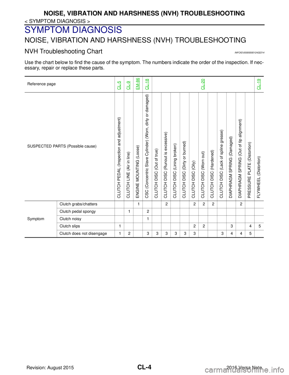
NVH Troubleshooting ChartINFOID:0000000012432214
Use the chart below to find the cause of the symptom. T he numbers indicate the order of the inspection. If nec-
essary, repair or replace these parts.
Reference pageCL-5CL-9EM-86CL-18CL-20CL-19
SUSPECTED PARTS (Possible cause)
CLUTCH PEDAL (Inspection and adjustment)
CLUTCH LINE (Air in line)
ENGINE MOUNTING (Loose)
CSC (Concentric Slave Cylinder) (Worn, dirty or damaged)
CLUTCH DISC (Out of true)
CLUTCH DISC (Ru nout is excessive)
CLUTCH DISC (Lining broken)
CLUTCH DISC (Dirty or burned)
CLUTCH DISC (Oily)
CLUTCH DISC (Worn out)
CLUTCH DISC (Hardened)
CLUTCH DISC (Lack of spline grease)
DIAPHRAGM SPRING (Damaged)
DIAPHRAGM SPRING (Out of tip alignment)
PRESSURE PLATE (Distortion)
FLYWHEEL (Distortion)
Symptom Clutch grabs/chatters
122 2 2 2
Clutch pedal spongy 1 2
Clutch noisy 1
Clutch slips 1 2 23 4 5
Clutch does not disengage 12 333333 3445
Revision: August 2015 2016 Versa Note
cardiagn.com
Page 1830 of 3641

FRONT WHEEL HUB AND KNUCKLEFAX-13
< REMOVAL AND INSTALLATION >
CEF
G H
I
J
K L
M A
B
FA X
N
O P
5. Perform inspection after assembly. Refer to FAX-13, "Inspection".
InspectionINFOID:0000000012431893
INSPECTION AFTER REMOVAL
Check the following items, and replace the part if necessary.
• Check components for deformation, cracks, and other damage.
• Check boots of transverse link and steering outer so cket ball joint for breakage, axial end play, and swing
torque. Refer to FSU-10, "
Inspection" and FSU-20, "Ball Joint".
INSPECTION AFTER DISASSEMBLY
Wheel Hub
• Check wheel hub for cracks (with magnetic exploration or dye testing). Replace if necessary.
Steering Knuckle
• Check steering knuckle for deformation, cracks, and other damage. Replace if any non-standard conditions
are found.
Snap Rings
• Check snap ring for wear or cracks. Replace if necessary.
INSPECTION AFTER ASSEMBLY
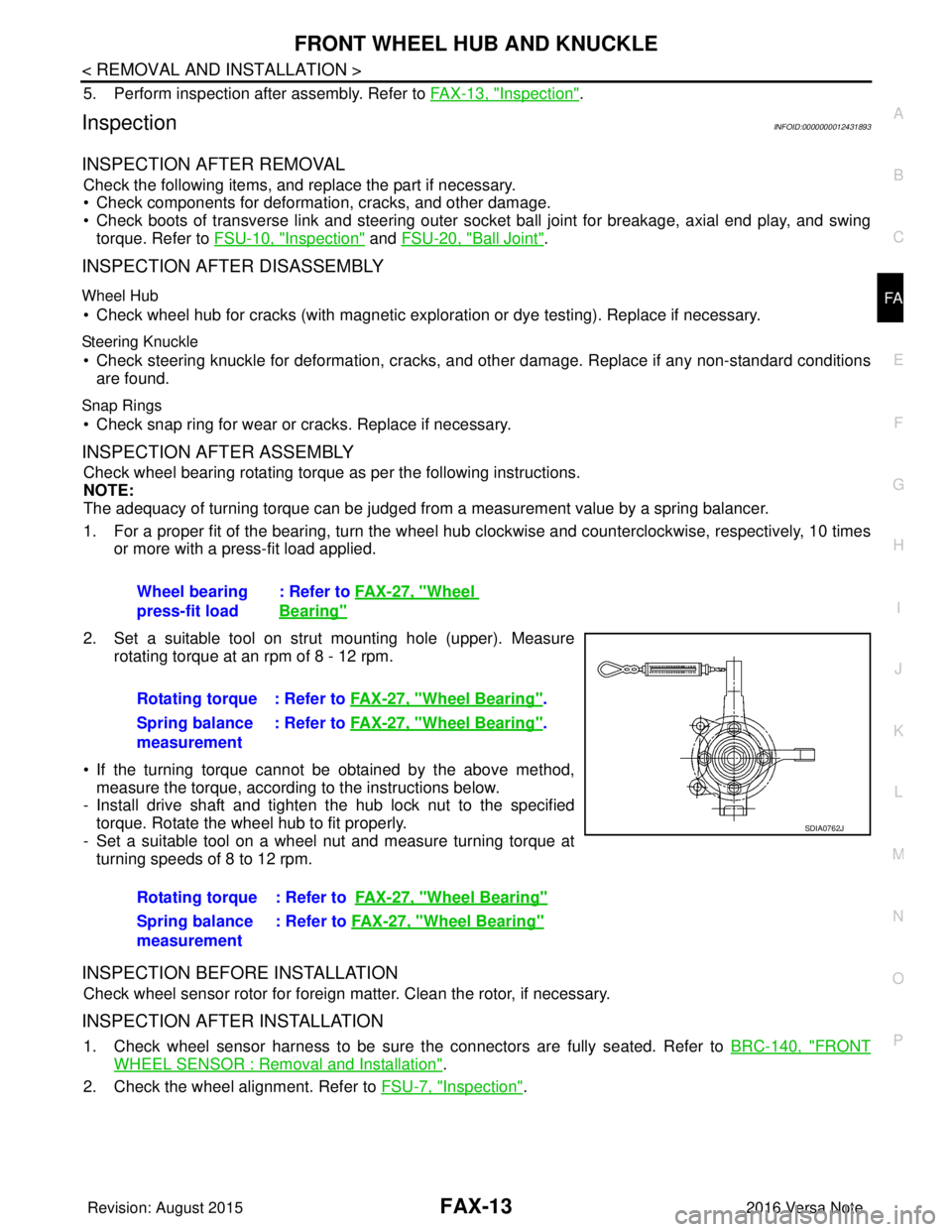
Check wheel bearing rotating torque as per the following instructions.
NOTE:
The adequacy of turning torque can be judged from a measurement value by a spring balancer.
1. For a proper fit of the bearing, turn the wheel hub clockwise and counterclockwise, respectively, 10 times
or more with a press-fit load applied.
2. Set a suitable tool on strut mounting hole (upper). Measure rotating torque at an rpm of 8 - 12 rpm.
• If the turning torque cannot be obtained by the above method, measure the torque, according to the instructions below.
- Install drive shaft and tighten the hub lock nut to the specified
torque. Rotate the wheel hub to fit properly.
- Set a suitable tool on a wheel nut and measure turning torque at turning speeds of 8 to 12 rpm.
INSPECTION BEFORE INSTALLATION
Check wheel sensor rotor for foreign matter. Clean the rotor, if necessary.
INSPECTION AFTER INSTALLATION
1. Check wheel sensor harness to be sure the connectors are fully seated. Refer to BRC-140, "FRONT
WHEEL SENSOR : Removal and Installation".
2. Check the wheel alignment. Refer to FSU-7, "
Inspection".
Wheel bearing
press-fit load
: Refer to
FAX-27, "
Wheel
Bearing"
Rotating torque : Refer to FAX-27, "Wheel Bearing".
Spring balance
measurement : Refer to
FAX-27, "
Wheel Bearing".
Rotating torque : Refer to FAX-27, "
Wheel Bearing"
Spring balance
measurement: Refer to
FAX-27, "Wheel Bearing"
SDIA0762J
Revision: August 2015 2016 Versa Note
cardiagn.com
Page 1832 of 3641

FRONT DRIVE SHAFT BOOTFAX-15
< REMOVAL AND INSTALLATION >
CEF
G H
I
J
K L
M A
B
FA X
N
O P
WHEEL SIDE : Removal and InstallationINFOID:0000000012431895
REMOVAL
1. Remove the wheel and tire using power tool. Refer to WT-48, "Removal and Installation".
2. Remove the brake caliper torque member bolts, leav ing the brake hose attached. Position the brake cali-
per aside with wire. Refer to BR-37, "
BRAKE CALIPER ASSEMBLY : Removal and Installation".
CAUTION:
Do not depress the brake pedal while the brake caliper is removed.
3. Put alignment marks on the disc brake rotor and on the wheel hub. Remove the disc brake rotor.
CAUTION:
Do not drop the disc brake rotor.
4. Remove the wheel sensor bolt. Position the wheel sensor and the wheel sensor harness aside. Refer to
BRC-140, "
FRONT WHEEL SENSOR : Removal and Installation".
5. Remove the cotter pin from the drive shaft.
6. Hold the wheel hub using Tool. Loosen the wheel hub lock nut.
7. Using a piece of wood and a suitable tool, tap on the wheel hub lock nut to disengage the drive shaft from the wheel hub.
CAUTION:
• Do not place the drive shaft joint at an extreme angle. Also be careful not to overextend slide
joint.
• Do not allow the drive shaft to hang down without support.
NOTE:
Use a suitable puller if the drive shaft cannot be separated from the wheel hub even after performing the
above procedure.
8. Remove the wheel hub lock nut.
9. Remove the nut and bolt from the lower ball joint. Disconnect the steering knuckle from the transverse
link.
10. Remove the drive shaft from the wheel hub.
11. Remove the boot bands.
12. Separate the boot from the joint sub-assembly.
13. Screw a suitable tool (A) into the joint sub-assembly screw part to a length of 30 mm (1.18 in) or more. Support the drive shaft
with one hand and pull out the joint sub-assembly from the shaft.
CAUTION:
• Align the suitable tool an d the drive shaft. Remove the
joint sub-assembly by pull ing firmly and uniformly.
• If the joint sub-assembly cannot be pulled out, try after removing the drive shaft from the vehicle. Refer to FA X -
22, "Disassembly and Assembly".
14. Remove the circular clip (1) from the shaft.
15. Remove the outer boot from the shaft. Tool number : KV4010104000 ( — )
JPDIF0258ZZ
JPDIF0007ZZ
Revision: August 2015
2016 Versa Note
cardiagn.com
Page 1835 of 3641

FAX-18
< REMOVAL AND INSTALLATION >
FRONT DRIVE SHAFT BOOT
• Check each mating surface for water and foreign matter. If there is any water or foreign matter,
clean the mating surface.
17. Install the transverse link to the steering knuckle with the nut and bolt. Refer to FSU-10, "
Exploded View".
18. Hold the wheel hub using a Tool. Tighten the wheel hub lock nut. CAUTION:
• Since the drive shaft is assembled by press-fitting, use a torque wrench to tighten the wheel hub
lock nut. Do not use a power tool.
• Too much torque causes axle noise. Too little torque causes wheel bearing looseness. Tighten the wheel hub lock nut to the specification.
19. Install the cotter pin. Securely bend the cotter pin to prevent rattles. CAUTION:
Do not reuse the cotter pin.
20. Install the wheel sensor, the wheel sensor bolt, and the wheel sensor harness. Refer to BRC-140,
"FRONT WHEEL SENSOR : Removal and Installation".
21. Align the matching marks on the disc brake roto r and on the wheel hub. Install the disc brake rotor.
CAUTION:
Do not drop the disc brake rotor.
22. Remove the wire from the brake caliper. Install the brake caliper and the brake caliper torque member
bolts. Refer to BR-37, "
BRAKE CALIPER ASSEMBLY : Removal and Installation".
CAUTION:
Do not twist the brake hose.
23. Install the wheel and tire. Refer to WT-48, "
Removal and Installation".
24. Complete the inspection. Refer to FAX-18, "
Inspection".
TRANSAXLE SIDE
TRANSAXLE SIDE : Removal and InstallationINFOID:0000000012431896
Remove boot after drive shaft is removed from the vehicle.
• For drive shaft removal and installation, refer to FAX-19, "
Removal and Installation".
• For drive shaft disassembly and assembly, refer to FAX-22, "
Disassembly and Assembly".
InspectionINFOID:0000000012431897
INSPECTION AFTER INSTALLATION
1. Check the wheel sensor harness to be sure the connectors are fully seated.
2. Check the wheel alignment. Refer to FSU-7, "
Inspection".
Tool number : KV4010104000 ( — )
Revision: August 2015
2016 Versa Note
cardiagn.com
Page 1846 of 3641

FSU-1
SUSPENSION
C
DF
G H
I
J
K L
M
SECTION FSU
A
B
FSU
N
O PCONTENTS
FRONT SUSPENSION
PRECAUTION ....... ........................................2
PRECAUTIONS .............................................. .....2
Precaution for Supplemental Restraint System
(SRS) "AIR BAG" and "SEAT BELT PRE-TEN-
SIONER" ............................................................. ......
2
Precaution for Procedure without Cowl Top Cover ......2
Precaution for Suspension ........................................2
PREPARATION ............................................3
PREPARATION .............................................. .....3
Special Service Tools .......................................... ......3
Commercial Service Tools ........................................3
SYMPTOM DIAGNOSIS ...............................5
NOISE, VIBRATION AND HARSHNESS
(NVH) TROUBLESHOOTING ........................ .....
5
NVH Troubleshooting Chart ................................ ......5
PERIODIC MAINTENANCE ..........................6
FRONT SUSPENSION ASSEMBLY .............. .....6
Inspection ............................................................ ......6
WHEEL ALIGNMENT ..........................................7
Inspection ............................................................ ......7
Adjustment ................................................................8
REMOVAL AND INSTALLATION ................9
FRONT COIL SPRING AND STRUT ............. .....9
Exploded View .................................................... ......9
Removal and Installation ...........................................9
TRANSVERSE LINK .........................................10
Exploded View ..................................................... ....10
Removal and Installation .........................................10
Inspection ................................................................10
FRONT STABILIZER ........................................12
Exploded View .........................................................12
Removal and Installation .........................................12
Inspection ................................................................13
UNIT REMOVAL AND INSTALLATION ......14
FRONT SUSPENSION MEMBER .....................14
Exploded View ..................................................... ....14
Removal and Installation .........................................14
Inspection ................................................................15
UNIT DISASSEMBLY AND ASSEMBLY ....16
FRONT COIL SPRING AND STRUT ................16
Exploded View ..................................................... ....16
Disassembly and Assembly .....................................16
Inspection ................................................................19
Disposal ...................................................................19
SERVICE DATA AND SPECIFICATIONS
(SDS) ............... .......................................... ...
20
SERVICE DATA AND SPECIFICATIONS
(SDS) .................................................................
20
Wheel Alignment (Unladen*1) ..................................20
Ball Joint .............................................................. ....20
Wheelarch Height (Unladen*) ..................................21
Revision: August 2015 2016 Versa Note
cardiagn.com