Page 2632 of 3641
PG
HARNESSPG-45
< WIRING DIAGRAM >
C
DE
F
G H
I
J
K L
B A
O P
N
ENGINE ROOM HARNESS
D2 M44 B/6 : Audio unit (With display audio system) C4 M204
W/6 : Heated seat switch LH
E2 M45 W/20 : Audio unit (With display audio system) D3 M215 W/4 : AUX in jack (With heated seats and NAVI
D5 M46 W/4 : Aux in jack (Without heated seats)
AAMIA0382ZZ
F1 E1 GR/5 : Front wiper motor E2 E40 B/2 : Brake fluid level switch
A5 E2 GR/2 : Front and rear washer motor F2 E41 L/5 : Starter relay
Revision: August 2015 2016 Versa Note
cardiagn.com
Page 3567 of 3641

WW-2
FRONT WIPER MOTOR HI CIRCUIT ................38
Component Function Check ................................ ...38
Diagnosis Procedure ..............................................38
FRONT WIPER AUTO STOP SIGNAL CIR-
CUIT ...................................................................
40
Component Function Check ................................ ...40
Diagnosis Procedure ..............................................40
FRONT WIPER MOTOR GROUND CIRCUIT ...42
Diagnosis Procedure ..............................................42
WASHER MOTOR CIRCUIT .............................43
Diagnosis Procedure ........................................... ...43
WASHER SWITCH ............................................44
Description ........................................................... ...44
Component Inspection ............................................44
REAR WIPER MOTOR CIRCUIT ......................46
Component Function Check ................................ ...46
Diagnosis Procedure ..............................................46
REAR WIPER AUTO STOP SIGNAL CIRCUIT
...
48
Component Function Check ................................ ...48
Diagnosis Procedure ..............................................48
SYMPTOM DIAGNOSIS .............................50
WIPER AND WASHER SYSTEM SYMPTOMS
...
50
Symptom Table ................................................... ...50
FRONT WIPER DOES NOT OPERATE ............53
Description ........................................................... ...53
Diagnosis Procedure ..............................................53
NORMAL OPERATING CONDITION ................55
Description ........................................................... ...55
REMOVAL AND INSTALLATION ...............56
WASHER TANK ............................................. ...56
Exploded View ..................................................... ...56
Removal and Installation ........................................56
FRONT WASHER MOTOR ................................58
Exploded View ..................................................... ...58
Removal and Installation ........................................58
WASHER FLUID LEVEL SWITCH ....................59
Removal and Installation ..................................... ...59
FRONT WASHER NOZZLE AND TUBE ...........60
Exploded View ..................................................... ...60
WASHER NOZZLE ................................................. ...60
WASHER NOZZLE : Removal and Installation .......60
WASHER NOZZLE : Adjustment ............................61
WASHER TUBE ..................................................... ...61
WASHER TUBE : Removal and Installation ...........61
WASHER TUBE : Inspection ..................................62
FRONT WIPER ARM .........................................63
Exploded View ..................................................... ...63
Removal and Installation .........................................63
Adjustment ........................................................... ...64
FRONT WIPER BLADE .....................................65
Removal and Installation .........................................65
FRONT WIPER DRIVE ASSEMBLY .............. ...66
Exploded View ..................................................... ...66
Removal and Installation .........................................66
Exploded View ..................................................... ...67
Disassembly and Assembly ....................................67
WIPER AND WASHER SWITCH ......................68
Removal and Installation .........................................68
REAR WIPER ARM ........................................ ...69
Exploded View ..................................................... ...69
Removal and Installation .........................................69
Adjustment ........................................................... ...70
REAR WIPER BLADE .......................................71
Removal and Installation .........................................71
REAR WIPER MOTOR ................................... ...72
Exploded View ..................................................... ...72
Removal and Installation .........................................72
REAR WASHER NOZZLE AND TUBE .......... ...73
Component Parts Location .................................. ...73
WASHER NOZZLE ................................................. ...73
WASHER NOZZLE : Removal and Installation .......73
WASHER NOZZLE : Adjustment ............................73
WASHER TUBE ..................................................... ...74
WASHER TUBE : Removal and Installation ...........74
SERVICE DATA AND SPECIFICATIONS
(SDS) .......... ................................. ...............
76
SERVICE DATA AND SPECIFICATIONS
(SDS) .............................................................. ...
76
Specifications ....................................................... ...76
Revision: August 2015 2016 Versa Note
cardiagn.com
Page 3572 of 3641

COMPONENT PARTSWW-7
< SYSTEM DESCRIPTION >
C
DE
F
G H
I
J
K
M A
B
WW
N
O P
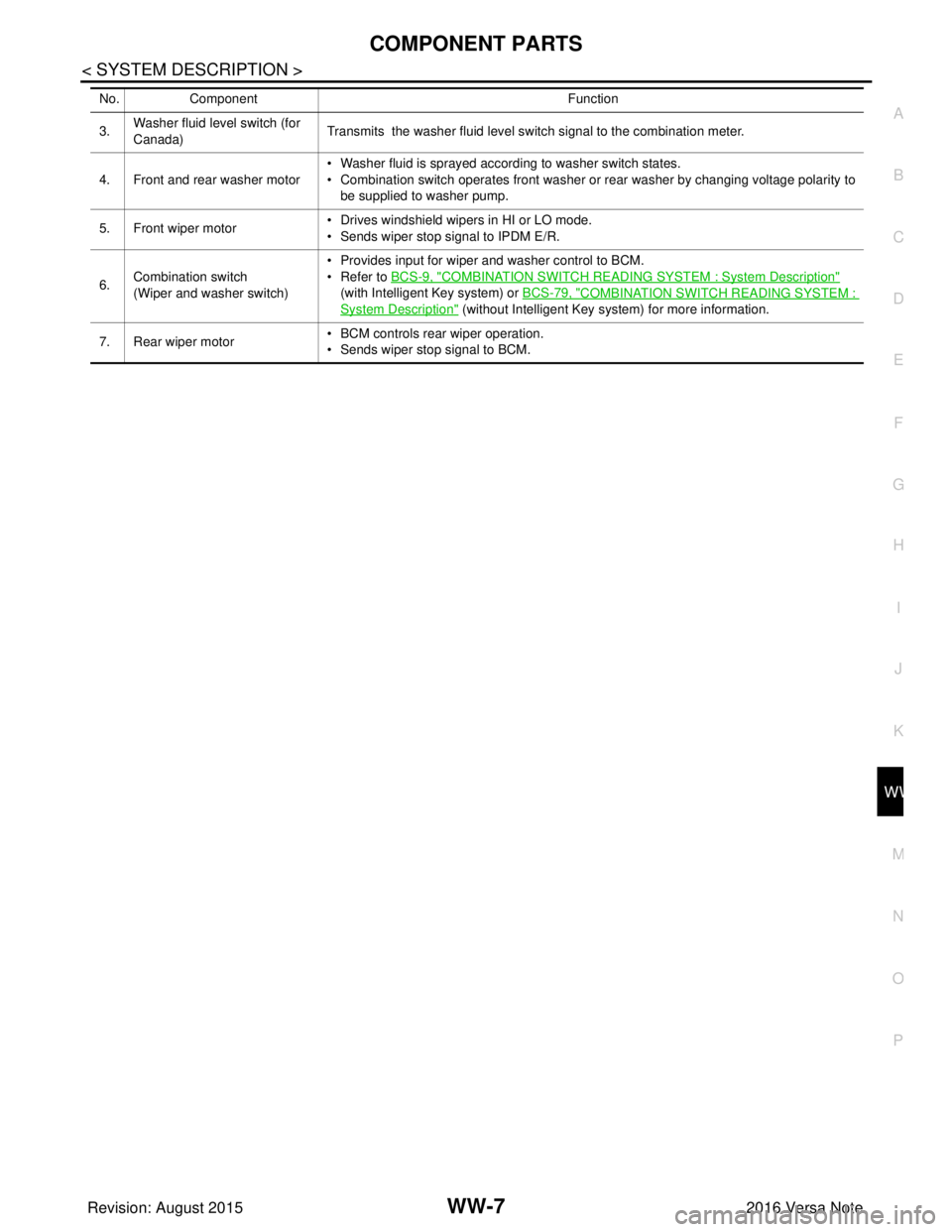
3. Washer fluid level switch (for
Canada) Transmits the washer fluid level switch signal to the combination meter.
4. Front and rear washer motor • Washer fluid is sprayed according to washer switch states.
• Combination switch operates front washer or rear washer by changing voltage polarity to
be supplied to washer pump.
5. Front wiper motor • Drives windshield wipers in HI or LO mode.
• Sends wiper stop signal to IPDM E/R.
6. Combination switch
(Wiper and washer switch) • Provides input for wiper and washer control to BCM.
• Refer to
BCS-9, "
COMBINATION SWITCH READING SYSTEM : System Description"
(with Intelligent Key system) or BCS-79, "
COMBINATION SWITCH READING SYSTEM :
System Description" (without Intelligent Key system) for more information.
7. Rear wiper motor • BCM controls rear wiper operation.
• Sends wiper stop signal to BCM.
No.
Component Function
Revision: August 2015 2016 Versa Note
cardiagn.com