2016 NISSAN NOTE bulb
[x] Cancel search: bulbPage 469 of 3641
![NISSAN NOTE 2016 Service Repair Manual SYSTEMBRC-21
< SYSTEM DESCRIPTION > [VDC/TCS/ABS]
C
D
E
G H
I
J
K L
M A
B
BRC
N
O PCONDITIONS FOR INDICATOR LAMP ILLUMINATION
• Turns ON when VDC and TCS functions are switched to non-operational s NISSAN NOTE 2016 Service Repair Manual SYSTEMBRC-21
< SYSTEM DESCRIPTION > [VDC/TCS/ABS]
C
D
E
G H
I
J
K L
M A
B
BRC
N
O PCONDITIONS FOR INDICATOR LAMP ILLUMINATION
• Turns ON when VDC and TCS functions are switched to non-operational s](/manual-img/5/57363/w960_57363-468.png)
SYSTEMBRC-21
< SYSTEM DESCRIPTION > [VDC/TCS/ABS]
C
D
E
G H
I
J
K L
M A
B
BRC
N
O PCONDITIONS FOR INDICATOR LAMP ILLUMINATION
• Turns ON when VDC and TCS functions are switched to non-operational status (OFF) by VDC OFF switch.
• Turns ON when ignition switch turns ON and turns OFF when the system is normal, for bulb check purposes.
CONDITIONS FOR WARNING LAMP ILLUMINATION
Turns ON when ignition switch turns ON and turns OFF when the system is normal, for bulb check purposes.
Component Function
Pump Returns the brake fluid reserved in reservoir to master cylinder by reducing pressure.
Motor Activates the pump according to signals from ABS actuator and electric unit (control unit).
Cut valve 1
Cut valve 2 Shuts off the ordinary brake line from master cylinder.
Suction valve 1
Suction valve 2 Supplies the brake fluid from master cylinder to the pump.
ABS IN valve Switches the fluid pressure line to increase or hold according to signals from control unit.
ABS OUT valve Switches the fluid pressure line to increase, hold or decrease according to signals from control unit.
Return check valve Returns the brake fluid from brake caliper and wheel cylinder to master cylinder by bypassing orifice
of each valve when brake is released.
Reservoir Temporarily reserves the brake fluid drained from brake caliper, so that pressure efficiently decreas-
es when decreasing pressure of brake caliper and wheel cylinder.
Pressure sensor Detects the brake fluid pressure and tr ansmits signal to ABS ac tuator and electric unit (control unit).
Condition (status) VDC OFF indicator lamp SLIP indicator lamp
Ignition switch OFF OFFOFF
For approx. 1 second after the ignition switch
is turned ON ON
ON
Approx. 1 second after ignition switch is
turned ON (when the system is in normal op-
eration) OFF
OFF
When VDC OFF switch is ON (VDC function
and TCS function are OFF) ON
OFF
VDC function is malfunctioning OFFON
TCS function is malfunctioning OFFON
Condition (status)ABS warning lamp Brake warning lamp
Ignition switch OFF OFFOFF
For approx. 1 second after the ignition switch
is turned ON ON
ON
Approx. 1 second after ignition switch is
turned ON (when the system is in normal op-
eration) OFF
OFF
After engine starts OFFOFF
When parking brake operates (parking brake
switch ON) OFF
ON
When brake fluid is less than the specified
level (brake fluid level switch ON) OFF
ON
VDC function is malfunctioning OFFOFF
TCS function is malfunctioning OFFOFF
ABS function is malfunctioning ONOFF
EBD function is malfunctioning ONON
Brake limited slip differential (BLSD) function
is malfunctioning OFF
OFF
Revision: August 2015 2016 Versa Note
cardiagn.com
Page 1153 of 3641
![NISSAN NOTE 2016 Service Repair Manual EC-26
< SYSTEM DESCRIPTION >[HR16DE]
COMPONENT PARTS
BATTERY TEMPERATURE SENSOR
Battery temperature sensor is int
egrated in battery current sensor.
The sensor measures temperature around the battery. NISSAN NOTE 2016 Service Repair Manual EC-26
< SYSTEM DESCRIPTION >[HR16DE]
COMPONENT PARTS
BATTERY TEMPERATURE SENSOR
Battery temperature sensor is int
egrated in battery current sensor.
The sensor measures temperature around the battery.](/manual-img/5/57363/w960_57363-1152.png)
EC-26
< SYSTEM DESCRIPTION >[HR16DE]
COMPONENT PARTS
BATTERY TEMPERATURE SENSOR
Battery temperature sensor is int
egrated in battery current sensor.
The sensor measures temperature around the battery.
The electrical resistance of the t hermistor decreases as temperature
increases.
*: These data are reference values and are measured between battery temperature
sensor signal terminal and sensor ground.
Malfunction Indicator Lamp (MIL)INFOID:0000000012431296
The MIL is located on the combination meter.
The MIL will illuminate when the ignition switch is turned ON without
the engine running. This is a bulb check.
When the engine is started, the MIL should turn OFF. If MIL remains
ON or continues blinking, the on board diagnostic system detects a
DTC(s) that affects exhaust gas.
For details, refer to EC-57, "
DIAGNOSIS DESCRIPTION : Malfunc-
tion Indicator Lamp (MIL)".
Mass Air Flow SensorINFOID:0000000012431297
The mass air flow sensor (1) is placed in the stream of intake air. It
measures the intake flow rate by measuring a part of the entire
intake flow. The mass air flow sensor controls the temperature of the
hot wire to a certain amount. The heat generated by the hot wire is
reduced as the intake air flows around it. The more air, the greater
the heat loss.
Therefore, the electric current supplied to hot wire is changed to
maintain the temperature of the hot wire as air flow increases. The
ECM detects the air flow by means of this current change.
Oil Pressure Warning LampINFOID:0000000012431298
Oil pressure warning lamp is located on the combination meter.
It indicates the low pressure of the engine oil and the malfunction of
the engine oil pressure system.
Combination meter turns the oil pressure warning lamp ON/OFF
according to the oil pressure warning lamp signal received from
ECM via CAN communication.
For details, refer to EC-43, "
ENGINE PROTECTION CONTROL AT
LOW ENGINE OIL PRESSURE : System Description".
Temperature [°C ( °F)]
Vo l ta g e* (V) Resistance (k
Ω)
25 (77) 3.3331.9 - 2.1
90 (194) 0.9690.222 - 0.258
SEF012P
SAT652J
PBIA9559J
PBIA8559J
Revision: August 2015 2016 Versa Note
cardiagn.com
Page 1184 of 3641
![NISSAN NOTE 2016 Service Repair Manual DIAGNOSIS SYSTEM (ECM)EC-57
< SYSTEM DESCRIPTION > [HR16DE]
C
D
E
F
G H
I
J
K L
M A
EC
NP
O
PERMANENT DTC SET TIMING
The setting timing of permanent DTC is stored in ECM
with the lighting of MIL when NISSAN NOTE 2016 Service Repair Manual DIAGNOSIS SYSTEM (ECM)EC-57
< SYSTEM DESCRIPTION > [HR16DE]
C
D
E
F
G H
I
J
K L
M A
EC
NP
O
PERMANENT DTC SET TIMING
The setting timing of permanent DTC is stored in ECM
with the lighting of MIL when](/manual-img/5/57363/w960_57363-1183.png)
DIAGNOSIS SYSTEM (ECM)EC-57
< SYSTEM DESCRIPTION > [HR16DE]
C
D
E
F
G H
I
J
K L
M A
EC
NP
O
PERMANENT DTC SET TIMING
The setting timing of permanent DTC is stored in ECM
with the lighting of MIL when a DTC is confirmed.
DIAGNOSIS DESCRIPTION : Malfunction Indicator Lamp (MIL)INFOID:0000000012431339
When emission-related ECU detects a malfunction in the emission
control systems components and/or the powertrain control compo-
nents (which affect vehicle emissions), it turns on/blinks MIL to
inform the driver that a malfunction has been detected.
1. The MIL illuminates when ignition switch is turned ON (engine is
not running).
NOTE:
Check the MIL circuit if MIL does not illuminate. Refer to EC-
456, "Diagnosis Procedure".
2. When the engine is start ed, the MIL should go off.
NOTE:
If MIL continues to illuminate/ blink, perform self-diagnoses and
inspect/repair accordingly because an emission-rela ted ECU has detected a malfunction in the emission
control systems components and/or the powertrain cont rol components (which affect vehicle emissions).
On Board Diagnosis FunctionINFOID:0000000012431340
ON BOARD DIAGNOSIS ITEM
The on board diagnostic system has the following functions.
BULB CHECK MODE
Description
This function allows damage inspection in the MIL bulb (blown, open circuit, etc.).
Operation Procedure
1. Turn ignition switch ON.
2. The MIL on the instrument panel should stay ON.
If it remains OFF, check MIL circuit. Refer to EC-456, "
Diagnosis Procedure".
SRT STATUS MODE
Description
This function allows to read if ECM has completed the self-diagnoses of major emission control systems and
components. For SRT, refer to EC-55, "
DIAGNOSIS DESCRIPTION : System Readiness Test (SRT) Code".
Operation Procedure
1. Turn ignition switch ON and wait 20 seconds.
2. SRT status is indicated as shown blow.
• ECM continues to illuminate MIL if all SRT codes are set.
SAT652J
Diagnostic test mode Function
Bulb check MIL can be checked.
SRT status ECM can read if SRT codes are set.
Malfunction warning If ECM detects a malfunction, it illuminates or blinks MIL to inform the driver that a malfunction
has been detected.
Self-diagnostic results DTCs or 1st trip DTCs stored in ECM can be read.
Accelerator pedal released position
learning ECM can learn the accelerator pedal released position. Refer to
EC-128, "
Description".
Throttle valve closed position learning ECM can learn the throttle valve closed position. Refer to EC-129, "
Description".
Idle air volume learning ECM can learn the idle air volume. Refer to EC-130, "
Description".
Mixture ratio self-learning value clear Mixture ratio self-learning value can be erased. Refer to EC-132, "
Description".
Revision: August 20152016 Versa Note
cardiagn.com
Page 1655 of 3641

EXL-3
C
DE
F
G H
I
J
K
M A
B
EXL
N
O P
FRONT FOG LAMP AIMING ADJUSTMENT ..100
Inspection ............................................................ ..100
Aiming Adjustment Procedure ...............................100
REMOVAL AND INSTALLATION .............102
FRONT COMBINATION LAMP ...................... ..102
Exploded View .................................................... ..102
Removal and Installation .......................................102
Bulb Replacement ........ .........................................102
FRONT FOG LAMP ........................................ ..104
Exploded View .................................................... ..104
Removal and Installation .......................................104
Bulb Replacement ........ .........................................105
DOOR MIRROR TURN SIGNAL LAMP ......... ..106
Removal and Installation .......................................106
Bulb Replacement ........ .........................................106
COMBINATION SWITCH ............................... ..107
Exploded View .................................................... ..107
Removal and Installation .......................................107
HAZARD SWITCH .......................................... ..108
Exploded View .................................................... ..108
Removal and Installation .......................................108
REAR COMBINATION LAMP ........................ ..109
Exploded View .................................................... ..109
Removal and Installation ..................................... ..109
Bulb Replacement .................................................109
HIGH-MOUNTED STOP LAMP ......................111
Exploded View .......................................................111
Removal and Installation .......................................111
Bulb Replacement .................................................111
LICENSE PLATE LAMP .................................112
Exploded View .......................................................112
Removal and Installation .......................................112
Bulb Replacement .................................................112
UNIT DISASSEMBLY AND ASSEMBLY ..113
FRONT COMBINATION LAMP ......................113
Exploded View ..................................................... ..113
Disassembly and Assembly ...................................113
REAR COMBINATION LAMP .........................114
Exploded View .......................................................114
Disassembly and Assembly ...................................114
SERVICE DATA AND SPECIFICATIONS
(SDS) ............... .......................................... .
115
SERVICE DATA AND SPECIFICATIONS
(SDS) ...............................................................
115
Bulb specification ................................................. ..115
Revision: August 2015 2016 Versa Note
cardiagn.com
Page 1729 of 3641

HEADLAMP (HI) CIRCUITEXL-77
< DTC/CIRCUIT DIAGNOSIS >
C
DE
F
G H
I
J
K
M A
B
EXL
N
O P
HEADLAMP (HI) CIRCUIT
DescriptionINFOID:0000000012432804
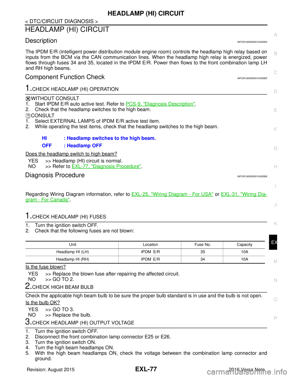
The IPDM E/R (intelligent power distribution modul e engine room) controls the headlamp high relay based on
inputs from the BCM via the CAN communication lines. When the headlamp high relay is energized, power
flows through fuses 34 and 35, located in the IPDM E/R. Power then flows to the front combination lamp LH
and RH high beams.
Component Function CheckINFOID:0000000012432805
1.CHECK HEADLAMP (HI) OPERATION
WITHOUT CONSULT
1. Start IPDM E/R auto active test. Refer to PCS-9, "
Diagnosis Description".
2. Check that the headlamp switches to the high beam.
CONSULT
1. Select EXTERNAL LAMPS of IP DM E/R active test item.
2. While operating the test items, check that the headlamp switches to the high beam.
Does the headlamp switch to high beam?
YES >> Headlamp (HI) circuit is normal.
NO >> Refer to EXL-77, "
Diagnosis Procedure".
Diagnosis ProcedureINFOID:0000000012432806
Regarding Wiring Diagram information, refer to EXL-25, "Wiring Diagram - For USA" or EXL-31, "Wiring Dia-
gram - For Canada".
1.CHECK HEADLAMP (HI) FUSES
1. Turn the ignition switch OFF.
2. Check that the following fuses are not blown:
Is the fuse blown?
YES >> Replace the blown fuse after repairing the affected circuit.
NO >> GO TO 2.
2.CHECK HIGH BEAM BULB
Check the applicable high beam bulb to be sure the proper bulb standard is in use and the bulb is not open.
Is the bulb OK?
YES >> GO TO 3.
NO >> Replace the bulb.
3.CHECK HEADLAMP (HI) OUTPUT VOLTAGE
1. Turn the ignition switch OFF.
2. Disconnect the front combination lamp connector E25 or E26.
3. Turn the ignition switch ON.
4. Turn the high beam headlamps ON.
5. With the high beam headlamps ON, check the vo ltage between the combination lamp connector and
ground. HI : Headlamp switches to the high beam.
OFF : Headlamp OFF
Unit
LocationFuse No.Capacity
Headlamp HI (LH) IPDM E/R3510A
Headlamp HI (RH) IPDM E/R3410A
Revision: August 2015 2016 Versa Note
cardiagn.com
Page 1731 of 3641

HEADLAMP (LO) CIRCUITEXL-79
< DTC/CIRCUIT DIAGNOSIS >
C
DE
F
G H
I
J
K
M A
B
EXL
N
O P
HEADLAMP (LO) CIRCUIT
DescriptionINFOID:0000000012432807
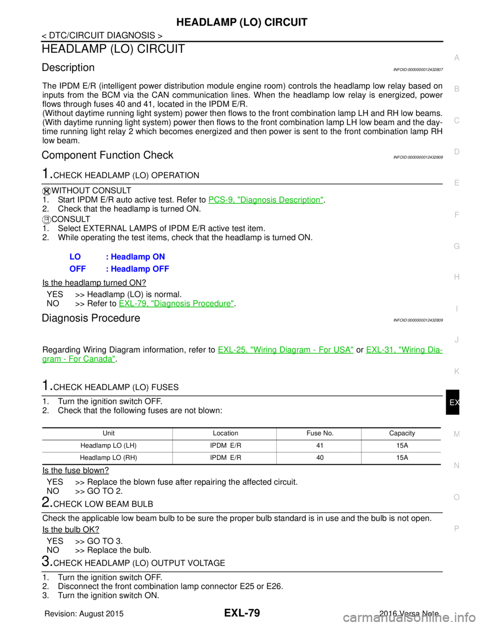
The IPDM E/R (intelligent power distribution modul e engine room) controls the headlamp low relay based on
inputs from the BCM via the CAN communication li nes. When the headlamp low relay is energized, power
flows through fuses 40 and 41, located in the IPDM E/R.
(Without daytime running light system) power then flow s to the front combination lamp LH and RH low beams.
(With daytime running light system) power then flows to the front combination lamp LH low beam and the day-
time running light relay 2 which becomes energized and t hen power is sent to the front combination lamp RH
low beam.
Component Function CheckINFOID:0000000012432808
1.CHECK HEADLAMP (LO) OPERATION
WITHOUT CONSULT
1. Start IPDM E/R auto active test. Refer to PCS-9, "
Diagnosis Description".
2. Check that the headlamp is turned ON.
CONSULT
1. Select EXTERNAL LAMPS of IP DM E/R active test item.
2. While operating the test items, check that the headlamp is turned ON.
Is the headlamp turned ON?
YES >> Headlamp (LO) is normal.
NO >> Refer to EXL-79, "
Diagnosis Procedure".
Diagnosis ProcedureINFOID:0000000012432809
Regarding Wiring Diagram information, refer to EXL-25, "Wiring Diagram - For USA" or EXL-31, "Wiring Dia-
gram - For Canada".
1.CHECK HEADLAMP (LO) FUSES
1. Turn the ignition switch OFF.
2. Check that the following fuses are not blown:
Is the fuse blown?
YES >> Replace the blown fuse after repairing the affected circuit.
NO >> GO TO 2.
2.CHECK LOW BEAM BULB
Check the applicable low beam bulb to be sure the proper bulb standard is in use and the bulb is not open.
Is the bulb OK?
YES >> GO TO 3.
NO >> Replace the bulb.
3.CHECK HEADLAMP (LO) OUTPUT VOLTAGE
1. Turn the ignition switch OFF.
2. Disconnect the front combination lamp connector E25 or E26.
3. Turn the ignition switch ON. LO : Headlamp ON
OFF : Headlamp OFF
Unit
LocationFuse No.Capacity
Headlamp LO (L H) IPDM E/R 4115A
Headlamp LO (RH) IPDM E/R4015A
Revision: August 2015 2016 Versa Note
cardiagn.com
Page 1734 of 3641

EXL-82
< DTC/CIRCUIT DIAGNOSIS >
PARKING LAMP CIRCUIT
PARKING LAMP CIRCUIT
DescriptionINFOID:0000000012432810
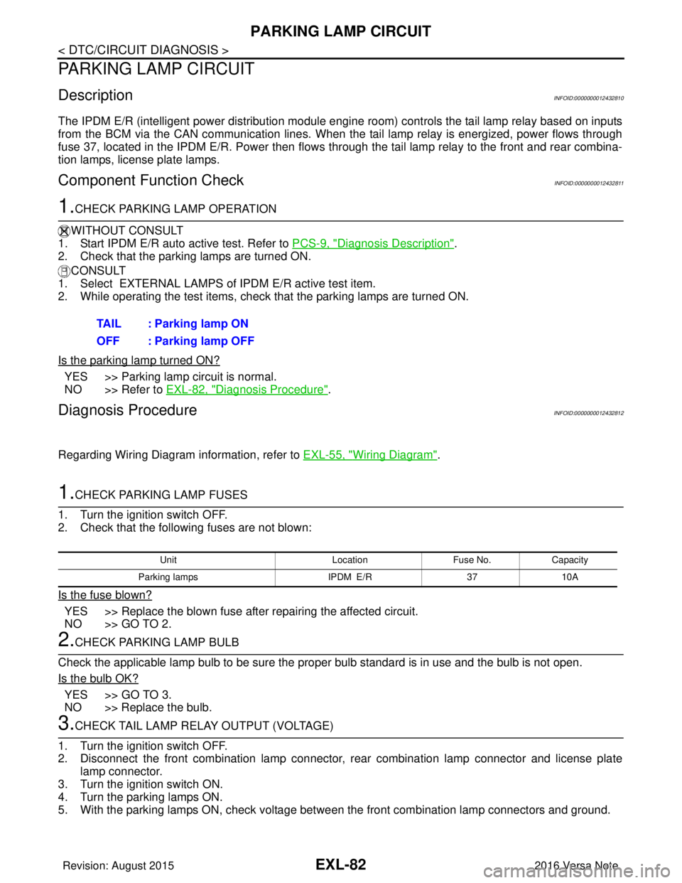
The IPDM E/R (intelligent power distribution module engine room) controls the tail lamp relay based on inputs
from the BCM via the CAN communication lines. When the tail lamp relay is energized, power flows through
fuse 37, located in the IPDM E/R. Power then flows through the tail lamp relay to the front and rear combina-
tion lamps, license plate lamps.
Component Function CheckINFOID:0000000012432811
1.CHECK PARKING LAMP OPERATION
WITHOUT CONSULT
1. Start IPDM E/R auto active test. Refer to PCS-9, "
Diagnosis Description".
2. Check that the parking lamps are turned ON.
CONSULT
1. Select EXTERNAL LAMPS of IPDM E/R active test item.
2. While operating the test items, check that the parking lamps are turned ON.
Is the parking lamp turned ON?
YES >> Parking lamp circuit is normal.
NO >> Refer to EXL-82, "
Diagnosis Procedure".
Diagnosis ProcedureINFOID:0000000012432812
Regarding Wiring Diagram information, refer to EXL-55, "Wiring Diagram".
1.CHECK PARKING LAMP FUSES
1. Turn the ignition switch OFF.
2. Check that the following fuses are not blown:
Is the fuse blown?
YES >> Replace the blown fuse after repairing the affected circuit.
NO >> GO TO 2.
2.CHECK PARKING LAMP BULB
Check the applicable lamp bulb to be sure the proper bulb standard is in use and the bulb is not open.
Is the bulb OK?
YES >> GO TO 3.
NO >> Replace the bulb.
3.CHECK TAIL LAMP RELAY OUTPUT (VOLTAGE)
1. Turn the ignition switch OFF.
2. Disconnect the front combination lamp connector, rear combination lamp connector and license plate
lamp connector.
3. Turn the ignition switch ON.
4. Turn the parking lamps ON.
5. With the parking lamps ON, check voltage between the front combination lamp connectors and ground. TAIL : Parking lamp ON
OFF : Parking lamp OFF
Unit
LocationFuse No.Capacity
Parking lamps IPDM E/R3710A
Revision: August 2015 2016 Versa Note
cardiagn.com
Page 1737 of 3641

TURN SIGNAL LAMP CIRCUITEXL-85
< DTC/CIRCUIT DIAGNOSIS >
C
DE
F
G H
I
J
K
M A
B
EXL
N
O P
TURN SIGNAL LAMP CIRCUIT
DescriptionINFOID:0000000012432813
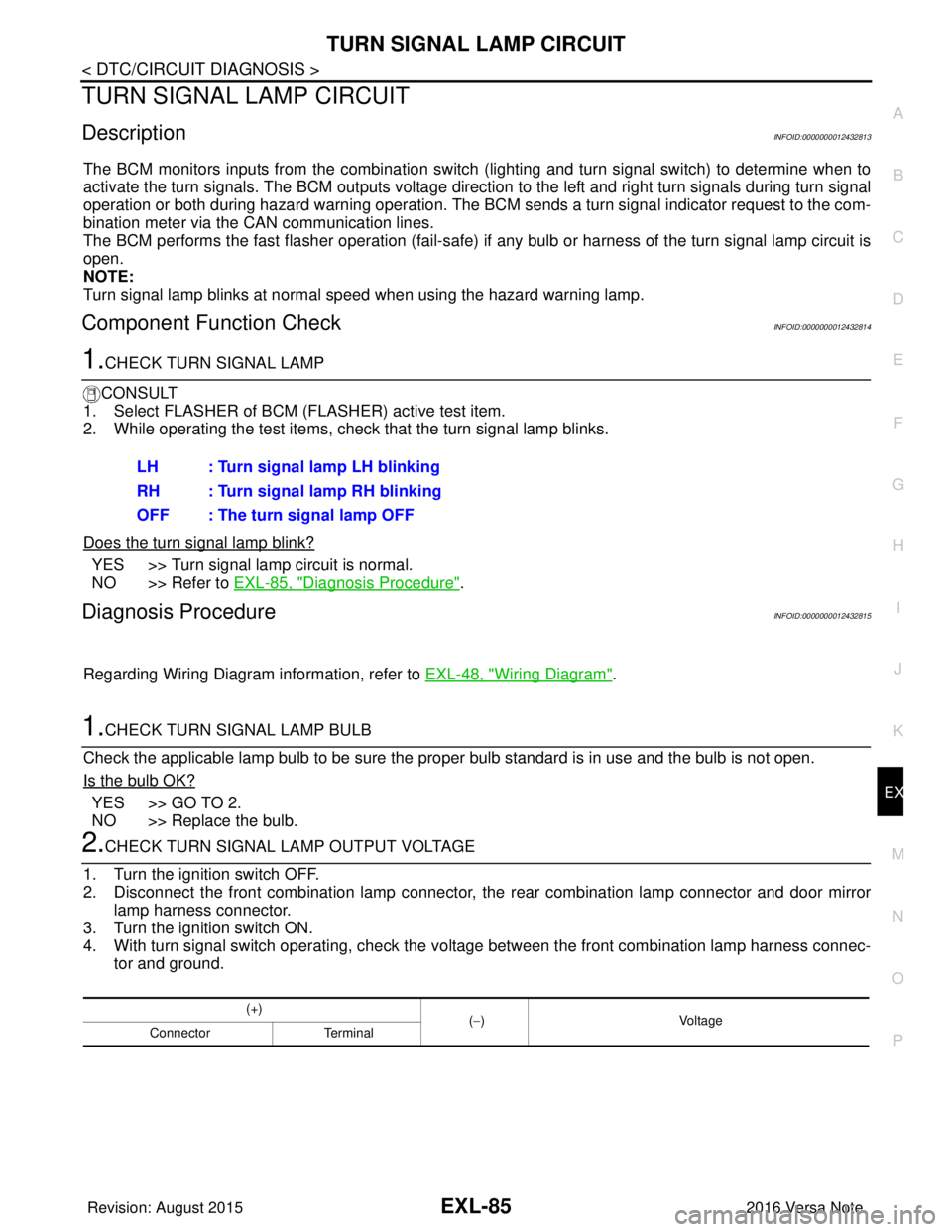
The BCM monitors inputs from the combination switch (lighting and turn signal switch) to determine when to
activate the turn signals. The BCM outputs voltage direction to the left and right turn signals during turn signal
operation or both during hazard warning operation. The BCM sends a turn signal indicator request to the com-
bination meter via the CAN communication lines.
The BCM performs the fast flasher operation (fail-safe) if any bulb or harness of the turn signal lamp circuit is
open.
NOTE:
Turn signal lamp blinks at normal speed when using the hazard warning lamp.
Component Function CheckINFOID:0000000012432814
1.CHECK TURN SIGNAL LAMP
CONSULT
1. Select FLASHER of BCM (FLASHER) active test item.
2. While operating the test items, check that the turn signal lamp blinks.
Does the turn signal lamp blink?
YES >> Turn signal lamp circuit is normal.
NO >> Refer to EXL-85, "
Diagnosis Procedure".
Diagnosis ProcedureINFOID:0000000012432815
Regarding Wiring Diagram information, refer to EXL-48, "Wiring Diagram".
1.CHECK TURN SIGNAL LAMP BULB
Check the applicable lamp bulb to be sure the proper bulb standard is in use and the bulb is not open.
Is the bulb OK?
YES >> GO TO 2.
NO >> Replace the bulb.
2.CHECK TURN SIGNAL LA MP OUTPUT VOLTAGE
1. Turn the ignition switch OFF.
2. Disconnect the front combination lamp connector, the rear combination lamp connector and door mirror
lamp harness connector.
3. Turn the ignition switch ON.
4. With turn signal switch operating, check the vo ltage between the front combination lamp harness connec-
tor and ground. LH : Turn signal lamp LH blinking
RH : Turn signal lamp RH blinking
OFF : The turn signal lamp OFF
(+)
(−) Voltage
Connector Terminal
Revision: August 2015 2016 Versa Note
cardiagn.com