Page 1740 of 3641

EXL-88
< DTC/CIRCUIT DIAGNOSIS >
FRONT FOG LAMP CIRCUIT
FRONT FOG LAMP CIRCUIT
Component Function CheckINFOID:0000000012432816
1.CHECK FRONT FOG LAMP OPERATION
WITHOUT CONSULT
1. Start IPDM E/R auto active test. Refer to PCS-9, "
Diagnosis Description".
2. Check that the front fog lamp is turned ON.
CONSULT
1. Select EXTERNAL LAMPS of IPDM E/R active test item.
2. While operating the test items, check that the front fog lamp is turned ON.
Is the front fog lamp turned ON?
YES >> Front fog lamp circuit is normal.
NO >> Refer to EXL-88, "
Diagnosis Procedure".
Diagnosis ProcedureINFOID:0000000012432817
Regarding Wiring Diagram information, refer to EXL-43, "Wiring Diagram".
1.CHECK FRONT FOG LAMP FUSE
1. Turn ignition switch OFF.
2. Check that the following fuse is not blown:
Is the fuse blown?
YES >> GO TO 2.
NO >> Replace the blown fuse after repairing the affected circuit.
2.CHECK FOG LAMP BULB
Check the applicable fog lamp bulb to be sure the proper bulb standard is in use and the bulb is not open.
Is the bulb OK?
YES >> GO TO 3.
NO >> Replace the bulb.
3.CHECK FRONT FOG LAMP OUTPUT VOLTAGE
CONSULT ACTIVE TEST
1. Turn ignition switch OFF.
2. Disconnect front fog lamp connector.
3. Turn ignition switch ON.
4. Select EXTERNAL LAMPS of IPDM E/R active test item.
5. While operating the fog lamps, check voltage between front fog lamp harness connector and ground.
FOG : Front fog lamp ON
OFF : Front fog lamp OFF
Unit
Fuse No.Capacity
Front fog lamp 3115 A
(+)
(−) Test item Vo l ta g e
(Approx.)
Front fog lamp
Connector Terminal
Revision: August 2015 2016 Versa Note
cardiagn.com
Page 1743 of 3641

EXTERIOR LIGHTING SYSTEM SYMPTOMSEXL-91
< SYMPTOM DIAGNOSIS >
C
DE
F
G H
I
J
K
M A
B
EXL
N
O P
SYMPTOM DIAGNOSIS
EXTERIOR LIGHTING SYSTEM SYMPTOMS
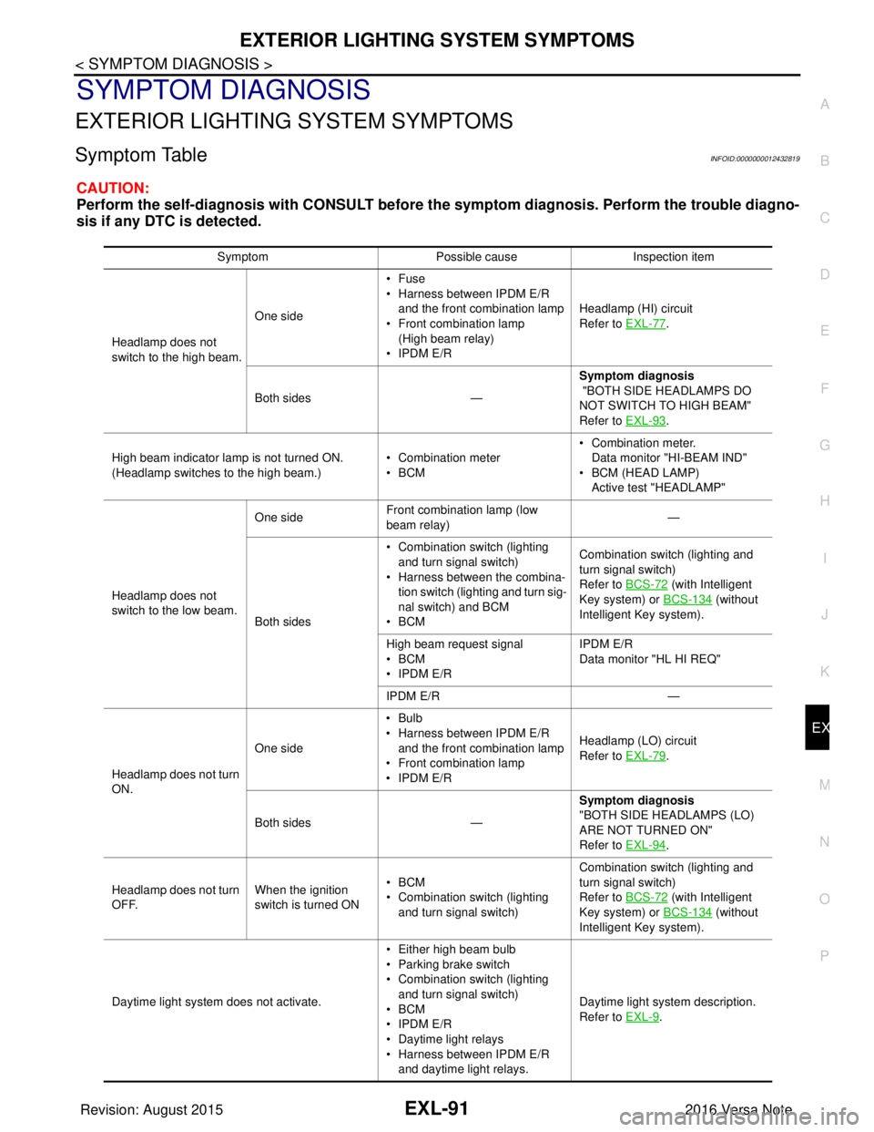
Symptom TableINFOID:0000000012432819
CAUTION:
Perform the self-diagnosis with CONSULT before th e symptom diagnosis. Perform the trouble diagno-
sis if any DTC is detected.
Symptom Possible causeInspection item
Headlamp does not
switch to the high beam. One side
•Fuse
• Harness between IPDM E/R
and the front combination lamp
• Front combination lamp
(High beam relay)
• IPDM E/R Headlamp (HI) circuit
Refer to EXL-77
.
Both sides — Symptom diagnosis
"BOTH SIDE HEADLAMPS DO
NOT SWITCH TO HIGH BEAM"
Refer to EXL-93
.
High beam indicator lamp is not turned ON.
(Headlamp switches to the high beam.) • Combination meter
•BCM• Combination meter.
Data monitor "HI-BEAM IND"
• BCM (HEAD LAMP)
Active test "HEADLAMP"
Headlamp does not
switch to the low beam. One side
Front combination lamp (low
beam relay) —
Both sides • Combination switch (lighting
and turn signal switch)
• Harness between the combina- tion switch (lighting and turn sig-
nal switch) and BCM
•BCM Combination switch (lighting and
turn signal switch)
Refer to BCS-72
(with Intelligent
Key system) or BCS-134
(without
Intelligent Key system).
High beam request signal
•BCM
• IPDM E/R IPDM E/R
Data monitor "HL HI REQ"
IPDM E/R —
Headlamp does not turn
ON. One side
•Bulb
• Harness between IPDM E/R
and the front combination lamp
• Front combination lamp
• IPDM E/R Headlamp (LO) circuit
Refer to EXL-79
.
Both sides — Symptom diagnosis
"BOTH SIDE HEADLAMPS (LO)
ARE NOT TURNED ON"
Refer to EXL-94
.
Headlamp does not turn
OFF. When the ignition
switch is turned ON•BCM
• Combination switch (lighting
and turn signal switch) Combination switch (lighting and
turn signal switch)
Refer to BCS-72
(with Intelligent
Key system) or BCS-134
(without
Intelligent Key system).
Daytime light system does not activate. • Either high beam bulb
• Parking brake switch
• Combination switch (lighting
and turn signal switch)
•BCM
• IPDM E/R
• Daytime light relays
• Harness between IPDM E/R
and daytime light relays. Daytime light system description.
Refer to EXL-9
.
Revision: August 2015
2016 Versa Note
cardiagn.com
Page 1744 of 3641

EXL-92
< SYMPTOM DIAGNOSIS >
EXTERIOR LIGHTING SYSTEM SYMPTOMS
Front fog lamp is not
turned ON.One side
• Front fog lamp bulb
• Harness between the front fog
lamp and ground Front fog lamp circuit
Refer to
EXL-88
.
Both sides —Symptom diagnosis
"BOTH SIDE FRONT FOG LAMPS
ARE NOT TURNED ON"
Refer to
EXL-96
.
Parking lamp is not
turned ON. One side
•Fuse
• Parking lamp bulb
• Harness between IPDM E/R
and the front/rear combination
lamp
• Front/rear combination lamp
• IPDM E/R Parking lamp circuit
Refer to
EXL-82
.
Both sides —Symptom diagnosis
"PARKING, LICENSE PLATE AND
TAIL LAMPS ARE NOT TURNED
ON"
Refer to
EXL-95
.
Turn signal lamp does
not blink. Indicator lamp is nor-
mal.
(The applicable side
performs the high
flasher activation).• Harness between BCM and
each turn signal lamp
• Turn signal lamp bulb Turn signal lamp circuit
Refer to
EXL-85
.
Turn signal indicator
lamp does not blink. One side
Combination meter —
Both sides
(Always) • Turn signal indicator lamp sig-
nal
• Combination meter
•BCM • Combination meter.
Data monitor "TURN IND"
• BCM (FLASHER) Active test "FLASHER"
Both sides
(Does blink when acti-
vating the hazard
warning lamp with the
ignition switch OFF) • The combination meter power
supply and the ground circuit
• Combination meter Combination meter
Power supply and the ground circuit
Refer to
MWI-43
(Type A).
Refer to MWI-98
(Type B).
Symptom
Possible causeInspection item
Revision: August 2015 2016 Versa Note
cardiagn.com
Page 1750 of 3641

EXL-98
< PERIODIC MAINTENANCE >
HEADLAMP AIMING ADJUSTMENT
Aiming Adjustment Procedure
INFOID:0000000012432829
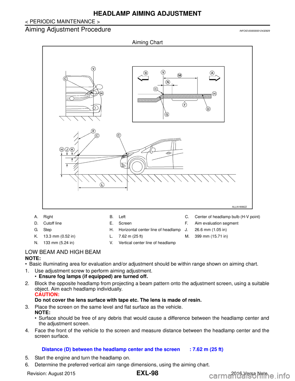
Aiming Chart
LOW BEAM AND HIGH BEAM
NOTE:
• Basic illuminating area for evaluation and/or adjus tment should be within range shown on aiming chart.
1. Use adjustment screw to perform aiming adjustment. •Ensure fog lamps (if eq uipped) are turned off.
2. Block the opposite headlamp from projecting a beam pa ttern onto the adjustment screen, using a suitable
object. Aim each headlamp individually.
CAUTION:
Do not cover the lens surface with tape etc. The lens is made of resin.
3. Place the screen on the same level and flat surface as the vehicle. NOTE:
• Surface should be free of any debris that would cause a difference between the headlamp center and
the adjustment screen.
4. Face the front of the vehicle to the screen and measure distance between the headlamp center and the screen surface.
5. Start the engine and turn the headlamp on.
6. Determine the preferred vertical aim range dimensions, using the aiming chart.
ALLIA1808ZZ
A. Right B. LeftC. Center of headlamp bulb (H-V point)
D. Cutoff line E. ScreenF. Aim evaluation segment
G. Step H. Horizontal center line of headlamp J. 26.6 mm (1.05 in)
K. 13.3 mm (0.52 in) L. 7.62 m (25 ft)M. 399 mm (15.71 in)
N. 133 mm (5.24 in) V. Vertical center line of headlamp
Distance (D) between the headlamp center and the screen : 7.62 m (25 ft)
Revision: August 2015 2016 Versa Note
cardiagn.com
Page 1754 of 3641

EXL-102
< REMOVAL AND INSTALLATION >
FRONT COMBINATION LAMP
REMOVAL AND INSTALLATION
FRONT COMBINATION LAMP
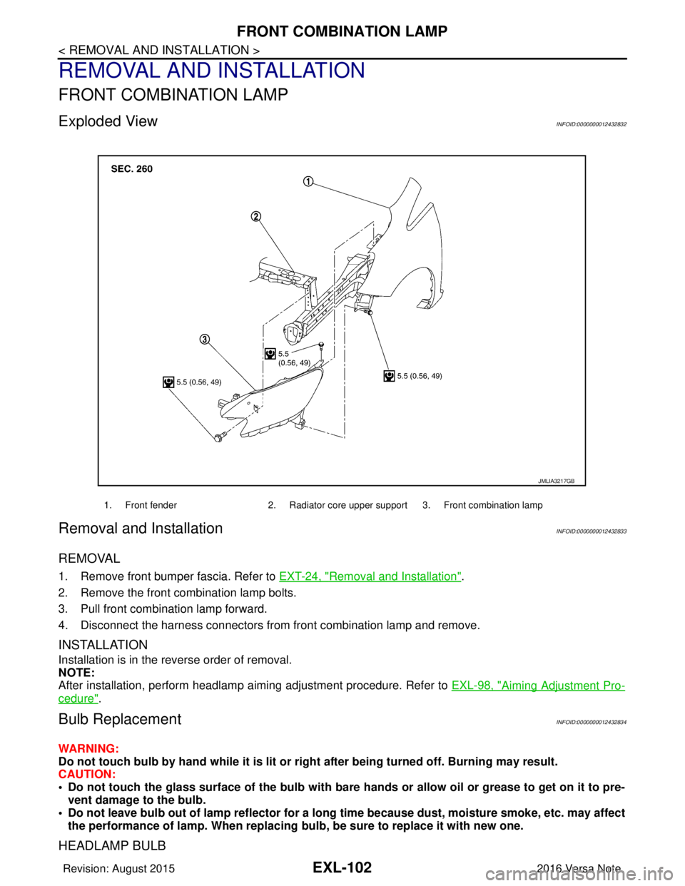
Exploded ViewINFOID:0000000012432832
Removal and InstallationINFOID:0000000012432833
REMOVAL
1. Remove front bumper fascia. Refer to EXT-24, "Removal and Installation".
2. Remove the front combination lamp bolts.
3. Pull front combination lamp forward.
4. Disconnect the harness connectors from front combination lamp and remove.
INSTALLATION
Installation is in the reverse order of removal.
NOTE:
After installation, perform headlamp aiming adjustment procedure. Refer to EXL-98, "
Aiming Adjustment Pro-
cedure".
Bulb ReplacementINFOID:0000000012432834
WARNING:
Do not touch bulb by hand while it is lit or right after being turned off. Burning may result.
CAUTION:
• Do not touch the glass surface of the bulb with bare hands or allow oil or grease to get on it to pre-
vent damage to the bulb.
• Do not leave bulb out of lamp reflector for a long time because dust, moisture smoke, etc. may affect
the performance of lamp. When replacing bulb, be sure to replace it with new one.
HEADLAMP BULB
1. Front fender2. Radiator core upper support 3. Front combination lamp
JMLIA3217GB
Revision: August 2015 2016 Versa Note
cardiagn.com
Page 1755 of 3641
FRONT COMBINATION LAMPEXL-103
< REMOVAL AND INSTALLATION >
C
DE
F
G H
I
J
K
M A
B
EXL
N
O P
Removal
1. Remove plastic cover.
2. Remove bulb from the front combination lamp.
Installation
Installation is in the reverse order of removal.
CAUTION:
After installing the bulb, install the bulb socket securely for watertightness.
SIDE MARKER LAMP BULB
Removal
1. Rotate bulb socket counterclockwise and remove.
2. Remove the bulb from bulb socket.
Installation
Installation is in the reverse order of removal.
CAUTION:
After installing the bulb, install the bulb socket securely for watertightness.
FRONT TURN SIGNAL/PARKING LAMP BULB
Removal
1. Rotate bulb socket counterclockwise and remove.
2. Remove the bulb from bulb socket.
Installation
Installation is in the reverse order of removal.
CAUTION:
After installing the bulb, install the bulb socket securely for watertightness.
Revision: August 2015
2016 Versa Note
cardiagn.com
Page 1757 of 3641
FRONT FOG LAMPEXL-105
< REMOVAL AND INSTALLATION >
C
DE
F
G H
I
J
K
M A
B
EXL
N
O P
Bulb ReplacementINFOID:0000000012432837
WARNING:
Do not touch bulb by hand while it is lit or right after being turned off. Burning may result.
CAUTION:
• Do not touch the glass surface of the bulb with bare hands or allow oi l or grease to get on it to pre-
vent damage to the bulb.
• Do not leave bulb out of lamp reflector for a long time because dust, moisture smoke, etc. may affect
the performance of lamp. When replacing bulb, be sure to replace it with new one.
REMOVAL
1. Partially remove fender protector. Refer to EXT-38, "Exploded View".
2. Disconnect harness connector (1) from front fog lamp bulb.
3. Rotate the bulb (2) counterclockwise and remove.
INSTALLATION
Installation is in the reverse order of removal.
CAUTION:
After installing the bulb, install the bulb socket securely for watertightness.
SKIB8304J
Revision: August 2015 2016 Versa Note
cardiagn.com
Page 1758 of 3641
EXL-106
< REMOVAL AND INSTALLATION >
DOOR MIRROR TURN SIGNAL LAMP
DOOR MIRROR TURN SIGNAL LAMP
Removal and InstallationINFOID:0000000012432838
REMOVAL
1. Remove the door mirror rear finisher. Refer to MIR-18, "Removal and Installation".
2. Remove the screws (A) and door mirror turn signal lamp (1).
3. Disconnect the harness connector from the door mirror turn signal lamp and remove.
INSTALLATION
Installation is in the reverse order of removal.
Bulb ReplacementINFOID:0000000012432839
DOOR MIRROR SIDE TURN SIGNAL LAMP
The door mirror side turn signal lamp bulb is integrated into the door mirror side turn signal lamp and is ser-
viced as an assembly. Refer to EXL-106, "
Removal and Installation".
ALLIA1492ZZ
Revision: August 2015 2016 Versa Note
cardiagn.com