2016 NISSAN NOTE bulb
[x] Cancel search: bulbPage 2096 of 3641

INL-2
DTC/CIRCUIT DIAGNOSIS ...................... ...39
POWER SUPPLY AND GROUND CIRCUIT .. ...39
BCM (BODY CONTROL SYSTEM) (WITH INTEL-
LIGENT KEY SYSTEM) ..... .......................................
39
BCM (BODY CONTROL S YSTEM) (WITH INTEL-
LIGENT KEY SYSTEM) : Dia gnosis Procedure .....
39
BCM (BODY CONTROL SYST EM) (WITHOUT IN-
TELLIGENT KEY SYSTEM) . ....................................
39
BCM (BODY CONTROL SYSTEM) (WITHOUT
INTELLIGENT KEY SYSTEM) : Diagnosis Proce-
dure ..................................................................... ...
39
BATTERY SAVER OUTPUT/POWER SUP-
PLY CIRCUIT .....................................................
41
Description ........................................................... ...41
Component Function Check ...................................41
Diagnosis Procedure ..............................................41
INTERIOR ROOM LAMP CONTROL CIRCUIT
...
43
Description ........................................................... ...43
Component Function Check ...................................43
Diagnosis Procedure ..............................................43
CARGO LAMP CONTROL CIRCUIT ................46
Description ........................................................... ...46
Component Function Check ...................................46
Diagnosis Procedure ..............................................46
PUSH-BUTTON IGNITION SWITCH ILLUMI-
NATION CIRCUIT ..............................................
48
Description ........................................................... ...48
Component Function Check ...................................48
Diagnosis Procedure ............................................ ...48
SYMPTOM DIAGNOSIS ............................50
INTERIOR LIGHTING SYSTEM SYMPTOMS ...50
Symptom Table .................................................... ...50
REMOVAL AND INSTALLATION ..............51
MAP LAMP ........................................................51
Exploded View ..................................................... ...51
Removal and Installation .........................................51
Bulb Replacement ................................................ ...51
INTERIOR ROOM LAMP ...................................53
Exploded View ..................................................... ...53
Removal and Installation .........................................53
Bulb Replacement ................................................ ...53
CARGO ROOM LAMP ......................................54
Exploded View ..................................................... ...54
Removal and Installation .........................................54
Bulb Replacement ................................................ ...54
SHIFT SELECTOR LAMP .................................55
Bulb Replacement ...................................................55
ILLUMINATION CONTROL SWITCH ...............56
Removal and Installation .........................................56
SERVICE DATA AND SPECIFICATIONS
(SDS) .......... ................................. ...............
57
SERVICE DATA AND SPECIFICATIONS
(SDS) .............................................................. ...
57
Bulb Specifications ............................................... ...57
Revision: August 2015 2016 Versa Note
cardiagn.com
Page 2099 of 3641
COMPONENT PARTSINL-5
< SYSTEM DESCRIPTION >
C
DE
F
G H
I
J
K
M A
B
INL
N
O P
SYSTEM DESCRIPTION
COMPONENT PARTS
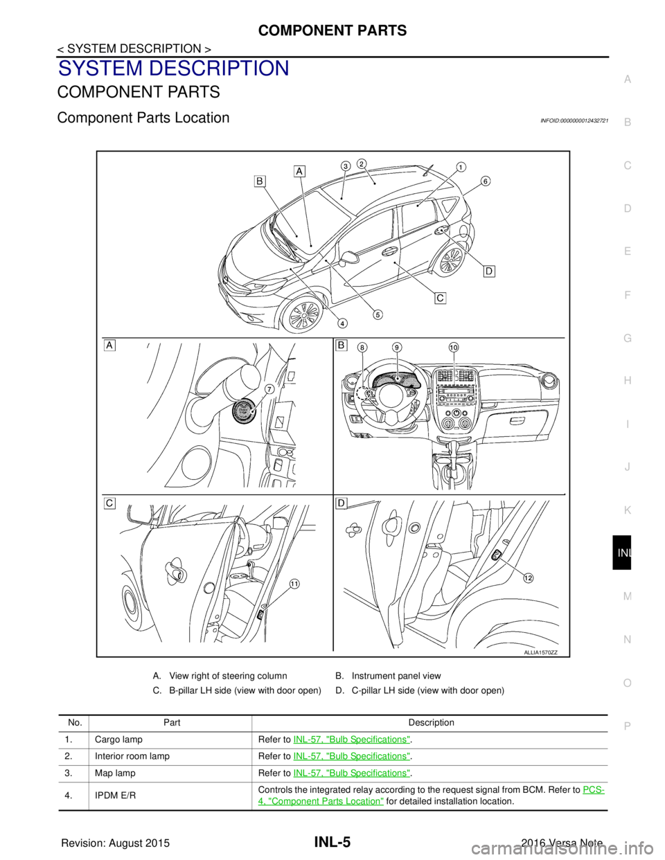
Component Parts LocationINFOID:0000000012432721
A. View right of steering column B. Instrument panel view
C. B-pillar LH side (view with door open) D. C-pillar LH side (view with door open)
No. Part Description
1. Cargo lamp Refer to INL-57, "
Bulb Specifications".
2. Interior room lamp Refer to INL-57, "
Bulb Specifications".
3. Map lamp Refer to INL-57, "
Bulb Specifications".
4. IPDM E/R Controls the integrated relay according to the request signal from BCM. Refer to
PCS-
4, "Component Parts Location" for detailed installation location.
ALLIA1570ZZ
Revision: August 2015 2016 Versa Note
cardiagn.com
Page 2137 of 3641
INTERIOR ROOM LAMP CONTROL CIRCUITINL-43
< DTC/CIRCUIT DIAGNOSIS >
C
DE
F
G H
I
J
K
M A
B
INL
N
O P
INTERIOR ROOM LAMP CONTROL CIRCUIT
DescriptionINFOID:0000000012432742
Controls each interior room lamp (ground side) by PWM signal.
NOTE:
PWM signal control period is approximately 250 Hz (in the gradual brightening/dimming).
Component Function CheckINFOID:0000000012432743
CAUTION:
Before performing the diagnosis, check that the following are normal.
• Interior room lamp power supply
• Map lamp bulb
• Room lamp bulb
1.CHECK INTERIOR ROOM LAMP CONTROL FUNCTION
CONSULT
1. Switch the map lamp switch or interior room lamp switch to DOOR.
2. Turn ignition switch ON.
3. Select INT LAMP of BCM (INT LAMP) ACTIVE TEST item.
4. While operating the test items, check that each interior room lamp turns ON/OFF.
Does the interior room lamp turn s ON/OFF (gradual brightening/dimming)?
YES >> Interior room lamp control circuit is normal.
NO >> Refer to INL-43, "
Diagnosis Procedure".
Diagnosis ProcedureINFOID:0000000012432744
Regarding Wiring Diagram information, refer to INL-21, "Wiring Diagram".
1.CHECK INTERIOR ROOM LAMP CONTROL OUTPUT
CONSULT
1. Turn ignition switch OFF.
2. Remove all the bulbs of map lamp and interior room lamp.
3. Turn ignition switch ON.
4. Select INT LAMP of BCM (INT LAMP) ACTIVE TEST item.
5. While operating the test item, check c ontinuity between BCM harness connector and ground.
With Intelligent Key system
Without Intelligent Key system
Is the inspection result normal?
YES >> GO TO 2.
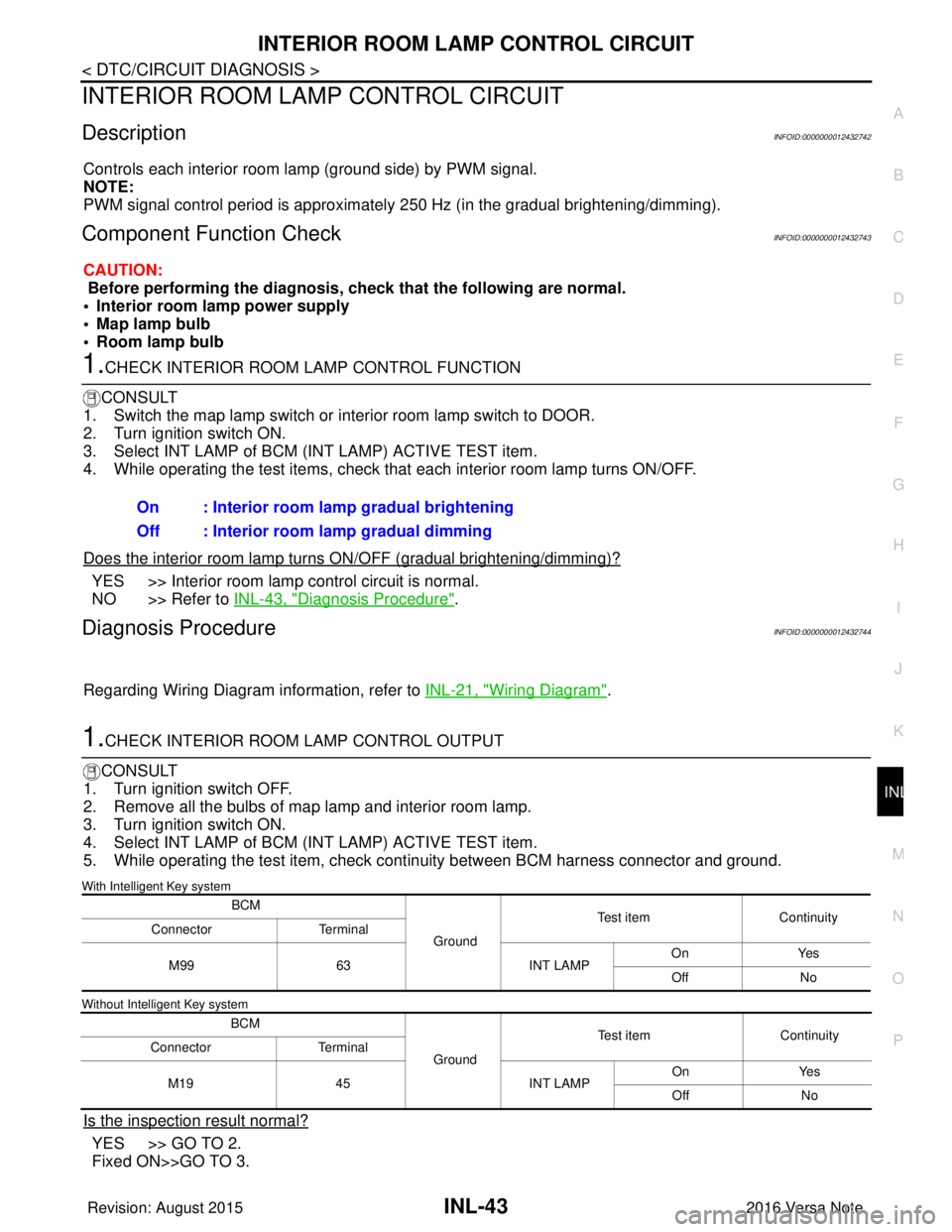
Fixed ON>>GO TO 3.On : Interior room lamp gradual brightening
Off : Interior room lamp gradual dimming
BCM
GroundTest item
Continuity
Connector Terminal
M99 63 INT LAMPOn
Yes
Off No
BCM GroundTest item
Continuity
Connector Terminal
M19 45 INT LAMPOn
Yes
Off No
Revision: August 2015 2016 Versa Note
cardiagn.com
Page 2140 of 3641

INL-46
< DTC/CIRCUIT DIAGNOSIS >
CARGO LAMP CONTROL CIRCUIT
CARGO LAMP CONTROL CIRCUIT
DescriptionINFOID:0000000012432745
Controls the cargo lamp (ground side) to turn the cargo lamp ON and OFF.
Component Function CheckINFOID:0000000012432746
CAUTION:
Before performing the diagnosis, check that the following is normal.
• Battery saver output/power supply
• Cargo lamp bulb
Diagnosis ProcedureINFOID:0000000012432747
Regarding Wiring Diagram information, refer to INL-21, "Wiring Diagram".
1.CHECK CARGO LAMP OUTPUT
1. Turn ignition switch OFF.
2. Remove the cargo lamp bulb.
3. Check continuity between BCM harness connector and ground.
With Intelligent Key system
Without Intelligent Key system
Is the inspection result normal?
YES >> GO TO 2.
Fixed ON>>GO TO 3.
Fixed OFF>>Replace BCM after making sure battery saver output/power supply circuit is not shorted to volt- age. Refer to BCS-74, "
Removal and Installation" (with Intelligent Key system) or BCS-137,
"Removal and Installation" (without Intelligent Key system).
2.CHECK CARGO LAMP OPEN CIRCUIT
Check continuity between BCM harness connector and cargo lamp harness connector.
With Intelligent Key system
Without Intelligent Key system
Is the inspection result normal?
YES >> Replace cargo lamp.
NO >> Repair or replace the harness or connector.
BCM
GroundCondition
Continuity
Connector Terminal
M100 49 Back doorOpen
Yes
Closed No
BCM GroundCondition
Continuity
Connector Terminal
M20 70 Back doorOpen
Yes
Closed No
BCM Cargo lamp
Continuity
Connector TerminalConnector Terminal
M100 49B21 4Yes
BCM Cargo lamp
Continuity
Connector TerminalConnector Terminal
M20 70B21 4Yes
Revision: August 2015 2016 Versa Note
cardiagn.com
Page 2145 of 3641
MAP LAMPINL-51
< REMOVAL AND INSTALLATION >
C
DE
F
G H
I
J
K
M A
B
INL
N
O P
REMOVAL AND INSTALLATION
MAP LAMP
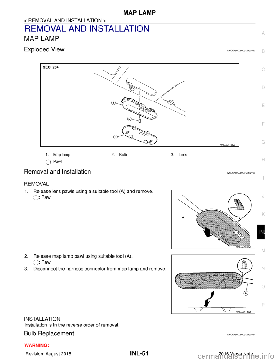
Exploded ViewINFOID:0000000012432752
Removal and InstallationINFOID:0000000012432753
REMOVAL
1. Release lens pawls using a suitable tool (A) and remove. : Pawl
2. Release map lamp pawl using suitable tool (A). : Pawl
3. Disconnect the harness connector from map lamp and remove.
INSTALLATION
Installation is in the reverse order of removal.
Bulb ReplacementINFOID:0000000012432754
WARNING:
1. Map lamp 2. Bulb3. Lens
Pawl
AWLIA2175ZZ
AWLIA2150ZZ
AWLIA2144ZZ
Revision: August 2015 2016 Versa Note
cardiagn.com
Page 2146 of 3641
INL-52
< REMOVAL AND INSTALLATION >
MAP LAMP
Do not touch bulb while it is lit or right after being turned OFF. Burning may result.
CAUTION:
• Do not touch the glass surface of the bulb with bare hands or allow oil or grease to get on it to pre-vent damage to bulb.
• Do not leave bulb out of lamp reflector for a long time because dust, moisture smoke, etc. may affect
the performance of lamp.
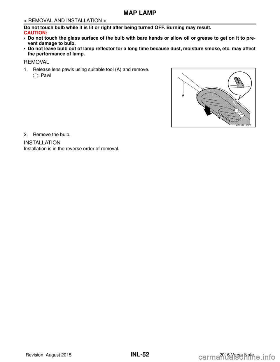
REMOVAL
1. Release lens pawls using suitable tool (A) and remove.
: Pawl
2. Remove the bulb.
INSTALLATION
Installation is in the reverse order of removal.
AWLIA2150ZZ
Revision: August 2015 2016 Versa Note
cardiagn.com
Page 2147 of 3641
INTERIOR ROOM LAMPINL-53
< REMOVAL AND INSTALLATION >
C
DE
F
G H
I
J
K
M A
B
INL
N
O P
INTERIOR ROOM LAMP
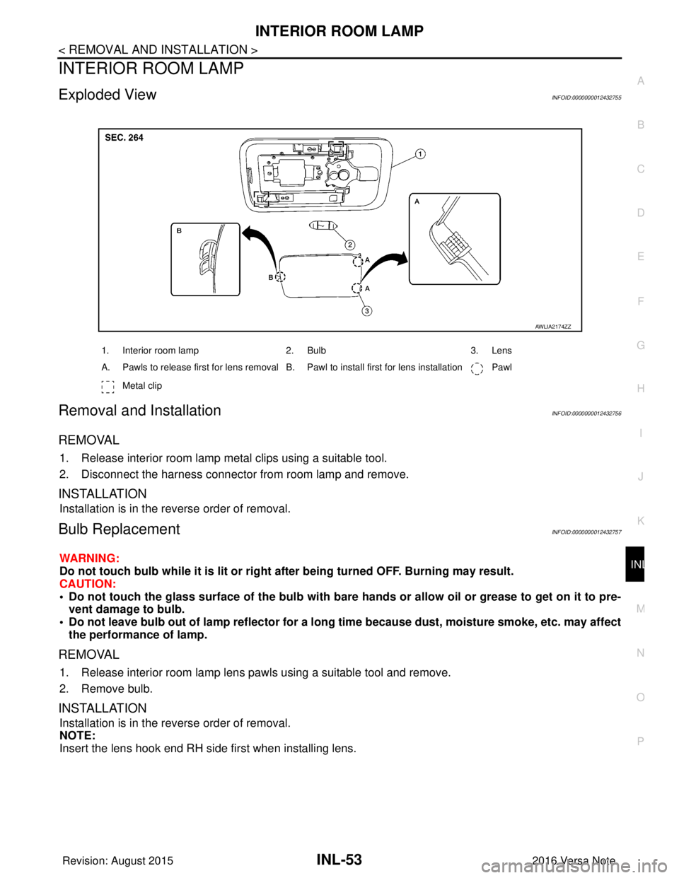
Exploded ViewINFOID:0000000012432755
Removal and InstallationINFOID:0000000012432756
REMOVAL
1. Release interior room lamp metal clips using a suitable tool.
2. Disconnect the harness connector from room lamp and remove.
INSTALLATION
Installation is in the reverse order of removal.
Bulb ReplacementINFOID:0000000012432757
WARNING:
Do not touch bulb while it is lit or right after being turned OFF. Burning may result.
CAUTION:
• Do not touch the glass surface of the bulb with bare hands or allow oi l or grease to get on it to pre-
vent damage to bulb.
• Do not leave bulb out of lamp reflector for a long time because dust, moisture smoke, etc. may affect the performance of lamp.
REMOVAL
1. Release interior room lamp lens pawls using a suitable tool and remove.
2. Remove bulb.
INSTALLATION
Installation is in the reverse order of removal.
NOTE:
Insert the lens hook end RH side first when installing lens.
1. Interior room lamp 2. Bulb3. Lens
A. Pawls to release first for lens removal B. Pawl to install first for lens installation Pawl
Metal clip
AWLIA2174ZZ
Revision: August 2015 2016 Versa Note
cardiagn.com
Page 2148 of 3641
INL-54
< REMOVAL AND INSTALLATION >
CARGO ROOM LAMP
CARGO ROOM LAMP
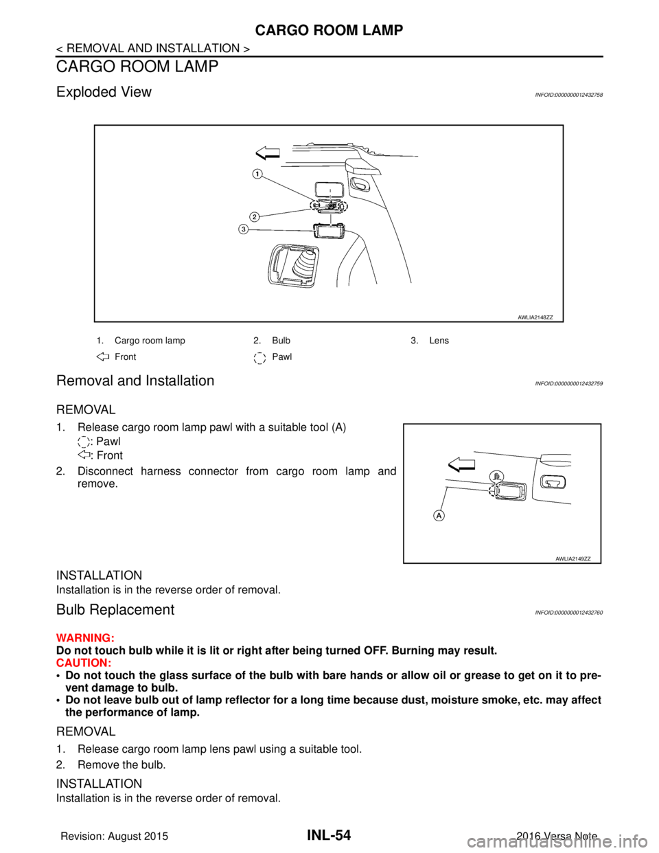
Exploded ViewINFOID:0000000012432758
Removal and InstallationINFOID:0000000012432759
REMOVAL
1. Release cargo room lamp pawl with a suitable tool (A): Pawl: Front
2. Disconnect harness connector from cargo room lamp and remove.
INSTALLATION
Installation is in the reverse order of removal.
Bulb ReplacementINFOID:0000000012432760
WARNING:
Do not touch bulb while it is lit or right after being turned OFF. Burning may result.
CAUTION:
• Do not touch the glass surface of the bulb with bare hands or allow oil or grease to get on it to pre-vent damage to bulb.
• Do not leave bulb out of lamp reflector for a long time because dust, moisture smoke, etc. may affect
the performance of lamp.
REMOVAL
1. Release cargo room lamp lens pawl using a suitable tool.
2. Remove the bulb.
INSTALLATION
Installation is in the reverse order of removal.
1. Cargo room lamp 2. Bulb3. Lens
Front Pawl
AWLIA2148ZZ
AWLIA2149ZZ
Revision: August 2015 2016 Versa Note
cardiagn.com