2016 NISSAN NOTE mirror
[x] Cancel search: mirrorPage 137 of 3641
![NISSAN NOTE 2016 Service Repair Manual AV-132
< SYSTEM DESCRIPTION >[NAVIGATION]
COMPONENT PARTS
Rear View Camera
INFOID:0000000012433006
• The rear view camera is installed in the back door finisher.
• Power is supplied from the arou NISSAN NOTE 2016 Service Repair Manual AV-132
< SYSTEM DESCRIPTION >[NAVIGATION]
COMPONENT PARTS
Rear View Camera
INFOID:0000000012433006
• The rear view camera is installed in the back door finisher.
• Power is supplied from the arou](/manual-img/5/57363/w960_57363-136.png)
AV-132
< SYSTEM DESCRIPTION >[NAVIGATION]
COMPONENT PARTS
Rear View Camera
INFOID:0000000012433006
• The rear view camera is installed in the back door finisher.
• Power is supplied from the around view monitor control unit (with around view monitor).
• Power is supplied from the AV control unit (without around view monitor).
Side CamerasINFOID:0000000012433007
• The side cameras are installed in the door mirrors.
• Power is supplied from the around view monitor control unit.
Front Camera INFOID:0000000012433008
• The front camera is installed in the front grille.
• Power is supplied from the around view monitor control unit.
Steering Angle SensorINFOID:0000000012433009
• Steering sensor is installed to the spiral cable.
• Steering angle sends the steering signal necessary for predictivecourse line via CAN communication.
Rod Antenna, Antenna Amp., Sate llite Antenna and Antenna FeederINFOID:0000000012433010
RADIO ANTENNA AND SATELLITE ANTENNA
JPNIA1452ZZ
JSNIA5397ZZ
JSNIA5398ZZ
JSNIA1571ZZ
Revision: August 2015 2016 Versa Note
cardiagn.com
Page 143 of 3641
![NISSAN NOTE 2016 Service Repair Manual AV-138
< SYSTEM DESCRIPTION >[NAVIGATION]
SYSTEM
SPEED SENSITIVE VOLUME SYSTEM
• Volume level of this system goes up and down aut
omatically in proportion to the vehicle speed.
• The control level NISSAN NOTE 2016 Service Repair Manual AV-138
< SYSTEM DESCRIPTION >[NAVIGATION]
SYSTEM
SPEED SENSITIVE VOLUME SYSTEM
• Volume level of this system goes up and down aut
omatically in proportion to the vehicle speed.
• The control level](/manual-img/5/57363/w960_57363-142.png)
AV-138
< SYSTEM DESCRIPTION >[NAVIGATION]
SYSTEM
SPEED SENSITIVE VOLUME SYSTEM
• Volume level of this system goes up and down aut
omatically in proportion to the vehicle speed.
• The control level can be selected by the customer.
HANDS-FREE PHONE SYSTEM
• Bluetooth® control is built into AV control unit.
• The connection between cellular phone and AV control unit is performed with Bluetooth
® communication.
• The voice guidance signal is input from the AV cont rol unit and output to the front speakers when operating
the cellular phone.
When A Call Is Originated
• Spoken voice sound output from the microphone (microphone signal) is input to AV control unit.
• AV control unit outputs to cellular phone with Bluetooth
® communication as a TEL voice signal.
• Voice sound is then heard at the other party.
When Receiving A Call
• Voice sound is input to own cellular phone from the other party.
• TEL voice signal is input to AV control unit by establishing Bluetooth
® communication from cellular phone,
and the signal is output to front speakers.
AROUND VIEW MONITOR FUNCTION
• This system is equipped with wide-angle cameras on the front, rear and right and left door mirrors.
• Images from front view, rear view, front-side view ( RH side), and birds-eye view are displayed to monitor the
vehicle surroundings.
• Around view monitor control unit expands the image received from each camera to create each view.
• In front view and rear view, the vehicle width, dist ance lines and predictive course lines are displayed.
• In front-side view, the vehicle distance guiding line and vehicle width guiding line are displayed.
• Birds-eye view converts the images from the camera s into an overhead view and displays the status of the
vehicle on the display. The vehicle icon that is displayed in the birds-eye view is depicted by the around view
monitor control unit.
Display
The around view monitor combines and displays travel direct ion view (front or rear), front-side view and birds-
eye view.
Operation
• The around view monitor operates by pressing the CAMERA switch on the AV control unit or by shifting the
selector lever to the R (reverse) position.
• When the selector lever is in any position other than R (reverse) and the CAMERA switch is pressed, the
screen displays front travel direction view and bird s-eye view. Pressing the CAMERA switch again changes
birds-eye view to front-side view
• When the selector lever is placed in R (reverse), the screen displays rear travel direction view and birds-eye view. Pressing the CAMERA switch changes birds-eye view to front-side view
JSNIA3982GB
Revision: August 2015 2016 Versa Note
cardiagn.com
Page 184 of 3641
![NISSAN NOTE 2016 Service Repair Manual AV
INSPECTION AND ADJUSTMENTAV-179
< BASIC INSPECTION > [NAVIGATION]
C
D
E
F
G H
I
J
K L
M B A
O P
PREDICTED COURSE LINE CENTER PO SITION ADJUSTMENT : Description
INFOID:0000000012433036
Adjust the ce NISSAN NOTE 2016 Service Repair Manual AV
INSPECTION AND ADJUSTMENTAV-179
< BASIC INSPECTION > [NAVIGATION]
C
D
E
F
G H
I
J
K L
M B A
O P
PREDICTED COURSE LINE CENTER PO SITION ADJUSTMENT : Description
INFOID:0000000012433036
Adjust the ce](/manual-img/5/57363/w960_57363-183.png)
AV
INSPECTION AND ADJUSTMENTAV-179
< BASIC INSPECTION > [NAVIGATION]
C
D
E
F
G H
I
J
K L
M B A
O P
PREDICTED COURSE LINE CENTER PO SITION ADJUSTMENT : Description
INFOID:0000000012433036
Adjust the center position of the predictive course line of the rear view monitor if it is shifted.
PREDICTED COURSE LINE CENTER POSITION ADJUSTMENT : Work Procedure
INFOID:0000000012433037
1.DRIVING
Drive the vehicle straight ahead 100 m (328.1 ft) or mo re at a speed of 30 km/h (18.6 MPH) or more.
>> END
CALIBRATING CAMERA IMAG E (AROUND VIEW MONITOR)
CALIBRATING CAMERA IMAGE (AROUND VIEW MONITOR) : Description
INFOID:0000000012433038
• Calibration must be performed after removing/replacing the cameras, removing parts (e.g. front grille, door
mirror, and others) mounted on the cameras, or replacing the Around view monitor control unit.
• The use of CONSULT is required to perform calibrati on or writing of calibration results to the Around view
monitor control unit.
• Align the white lines on the road near the vehicle at the boundary of each camera image by this camera cal- ibration. The white lines far from the vehicle may not be aligned at the boundary of each camera image. The
farther the line, the greater the difference is.
CALIBRATING CAMERA IMAGE (AROUND VI EW MONITOR) : Work Procedure
INFOID:0000000012433039
CALIBRATION FLOWCHART
Following the flowchart shown in the figure, perform the calibration.
NOTE:
JSNIA4210GB
Revision: August 2015 2016 Versa Note
cardiagn.com
Page 257 of 3641
![NISSAN NOTE 2016 Service Repair Manual A V -252
< REMOVAL AND INSTALLATION >[NAVIGATION]
SIDE CAMERA
SIDE CAMERA
Exploded ViewINFOID:0000000012433104
Removal and InstallationINFOID:0000000012433105
REMOVAL
1. Remove the door mirror. Refer NISSAN NOTE 2016 Service Repair Manual A V -252
< REMOVAL AND INSTALLATION >[NAVIGATION]
SIDE CAMERA
SIDE CAMERA
Exploded ViewINFOID:0000000012433104
Removal and InstallationINFOID:0000000012433105
REMOVAL
1. Remove the door mirror. Refer](/manual-img/5/57363/w960_57363-256.png)
A V -252
< REMOVAL AND INSTALLATION >[NAVIGATION]
SIDE CAMERA
SIDE CAMERA
Exploded ViewINFOID:0000000012433104
Removal and InstallationINFOID:0000000012433105
REMOVAL
1. Remove the door mirror. Refer to
MIR-15, "Removal and Installation".
2. Remove the door mirror glass.
3. Remove the door mirror actuator.
4. Disconnect the harness connector from the side camera.
5. Remove the side camera screws and remove.
INSTALLATION
Installation is in the reverse order of removal.
NOTE:
Perform camera image calibration. Refer to AV-179, "
CALIBRATING CAMERA IMAGE (AROUND VIEW
MONITOR) : Description".
1. Door mirror rear finisher 2.Side turn signal lamp (if
equipped)
3. Door mirror
4. Door mirror glass 5. Side camera 6. Door mirror base finisher
Pawl
AWLIA2708ZZ
Revision: August 2015 2016 Versa Note
cardiagn.com
Page 401 of 3641

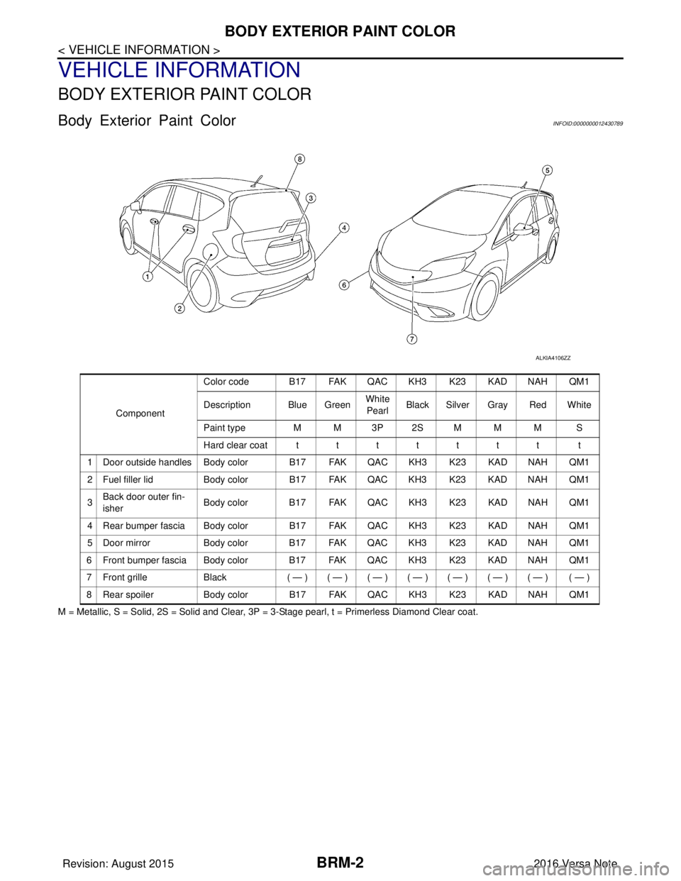
BRM-2
< VEHICLE INFORMATION >
BODY EXTERIOR PAINT COLOR
VEHICLE INFORMATION
BODY EXTERIOR PAINT COLOR
Body Exterior Paint ColorINFOID:0000000012430789
M = Metallic, S = Solid, 2S = Solid and Clear, 3P = 3-Stage pearl, t = Primerless Diamond Clear coat.
ALKIA4106ZZ
ComponentColor code B17 FAK QAC KH3 K23 KAD NAH QM1
Description Blue Green
White
Pearl Black Silver Gray Red White
Paint type MM3P2SMMM S
Hard clear coatttttttt t
1 Door outside handles Body color B17 FAK QAC KH3 K23 KAD NAH QM1
2 Fuel filler lid Body color B17 FAK QAC KH3 K23 KAD NAH QM1
3 Back door outer fin-
isher Body color B17 FAK QAC KH3 K23 KAD NAH QM1
4 Rear bumper fascia Body color B17 FAK QAC KH3 K23 KAD NAH QM1
5 Door mirror Body color B17 FAK QAC KH3 K23 KAD NAH QM1
6 Front bumper fascia Body color B17 FAK QAC KH3 K23 KAD NAH QM1
7Front grille Black ( — )( — )( — )( — )( — )( — )( — ) ( — )
8 Rear spoiler Body color B17 FAK QAC KH3 K23 KAD NAH QM1
Revision: August 2015 2016 Versa Note
cardiagn.com
Page 404 of 3641

HANDLING PRECAUTIONS FOR PLASTICSBRM-5
< PRECAUTION >
C
DE
F
G H
I
J
L
M A
B
BRM
N
O P
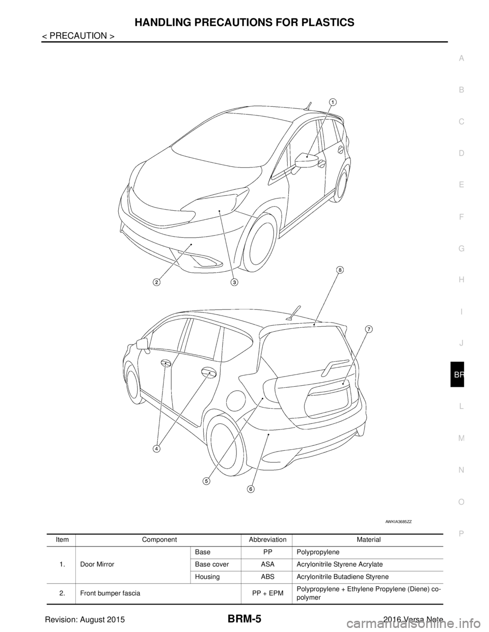
Item Component Abbreviation Material
1. Door Mirror Base
PP Polypropylene
Base cover ASA Acryloni trile Styrene Acrylate
Housing ABS Acrylonitrile Butadiene Styrene
2. Front bumper fascia PP + EPMPolypropylene + Ethylene Propylene (Diene) co-
polymer
AWKIA3685ZZ
Revision: August 2015
2016 Versa Note
cardiagn.com
Page 652 of 3641

DEF-1
DRIVER CONTROLS
C
DE
F
G H
I
J
K
M
SECTION DEF
A
B
DEF
N
O P
CONTENTS
DEFOGGER
PRECAUTION ....... ........................................3
PRECAUTIONS .............................................. .....3
Precaution for Supplemental Restraint System
(SRS) "AIR BAG" and "SEAT BELT PRE-TEN-
SIONER" ............................................................. ......
3
SYSTEM DESCRIPTION ..............................4
COMPONENT PARTS ................................... .....4
Component Parts Location .................................. ......4
Rear window defogger ..............................................5
Door mirror defogger .................................................5
SYSTEM ..............................................................6
System Description ............................................. ......6
DIAGNOSIS SYSTEM (BCM) (WITH INTELLI-
GENT KEY SYSTEM) ..........................................
7
COMMON ITEM ..................................................... ......7
COMMON ITEM : CONSULT Function (BCM -
COMMON ITEM) .......................................................
7
REAR DEFOGGER ............................................... ......8
REAR DEFOGGER : CONSULT Function (BCM -
REAR DEFOGGER) ........................................... ......
8
DIAGNOSIS SYSTEM (BCM) (WITHOUT IN-
TELLIGENT KEY SYSTEM) ................................
9
COMMON ITEM ..................................................... ......9
COMMON ITEM : CONSULT Function (BCM -
COMMON ITEM) .......................................................
9
REAR DEFOGGER ............................................... ....10
REAR DEFOGGER : CONSULT Function (BCM -
REAR DEFOGGER) ........................................... ....
10
ECU DIAGNOSIS INFORMATION ..............11
BCM ................................................................ ....11
List of ECU Reference ........................................ ....11
WIRING DIAGRAM ......................................12
REAR WINDOW DE FOGGER SYSTEM ..........12
Wiring Diagram .................................................... ....12
BASIC INSPECTION ...................................17
DIAGNOSIS AND REPAIR WORK FLOW .......17
Work Flow ............................................................ ....17
DTC/CIRCUIT DIAGNOSIS .........................20
REAR WINDOW DEFOGGER SWITCH ...........20
Description ........................................................... ....20
Component Function Check ....................................20
Diagnosis Procedure ...............................................20
Component Inspection .............................................21
REAR WINDOW DEFOGGER RELAY .............22
Description ...............................................................22
Component Function Check ....................................22
Diagnosis Procedure ...............................................22
Component Inspection .............................................23
REAR WINDOW DEFOGGER POWER SUP-
PLY AND GROUND CIRCUIT ..........................
24
Description ...............................................................24
Component Function Check ....................................24
Diagnosis Procedure ...............................................24
Component Inspection .............................................25
DRIVER SIDE DOOR MIRROR DEFOGGER ...26
Description ...............................................................26
Component Function Check ....................................26
Diagnosis Procedure ...............................................26
Component Inspection .............................................27
PASSENGER SIDE DOOR MIRROR DEFOG-
GER ...................................................................
28
Description ...............................................................28
Component Function Check ....................................28
Diagnosis Procedure ...............................................28
Revision: August 2015 2016 Versa Note
cardiagn.com
Page 653 of 3641

DEF-2
Component Inspection ............................................29
SYMPTOM DIAGNOSIS .............................30
REAR WINDOW DEFOGGER AND DOOR
MIRROR DEFOGGER DO NOT OPERATE. .. ...
30
Diagnosis Procedure ........................................... ...30
REAR WINDOW DEFOGGER DOES NOT
OPERATE BUT BOTH OF DOOR MIRROR
DEFOGGER OPERATE. ...................................
31
Diagnosis Procedure ........................................... ...31
BOTH DOORS MIRROR DEFOGGER DON’T
OPERATE BUT REAR WINDOW DEFOG-
GER OPERATES ...............................................
32
Diagnosis Procedure ........................................... ...32
DRIVER SIDE DOOR MIRROR DEFOGGER
DOES NOT OPERATE. .....................................
33
Diagnosis Procedure ............................................ ...33
PASSENGER SIDE DOOR MIRROR DEFOG-
GER DOES NOT OPERATE. ............................
34
Diagnosis Procedure ............................................ ...34
REAR WINDOW DEFOGGER SWITCH DOES
NOT LIGHT, BUT REAR WINDOW DEFOG-
GER OPERATES ...............................................
35
Diagnosis Procedure ............................................ ...35
REMOVAL AND INSTALLATION ..............36
FILAMENT ...................................................... ...36
Inspection and Repair .......................................... ...36
CONDENSER ....................................................38
Removal and Installation .........................................38
Revision: August 2015 2016 Versa Note
cardiagn.com